2006 SUZUKI SX4 602
[x] Cancel search: 602Page 1372 of 1556
Downloaded from www.Manualslib.com manuals search engine 9C-20 Instrumentation / Driver Info. / Horn:
GPS Antenna Removal and Installation (If
Equipped)
S6RW0D9306027
Removal
1) Remove combination meter cluster panel referring to
step 1) to 4) of “Combination Meter Removal and
Installation”.
2) Disconnect GPS antenna connector from navigation
unit referring to “Audio Unit Removal and Installation
(If Equipped)”.
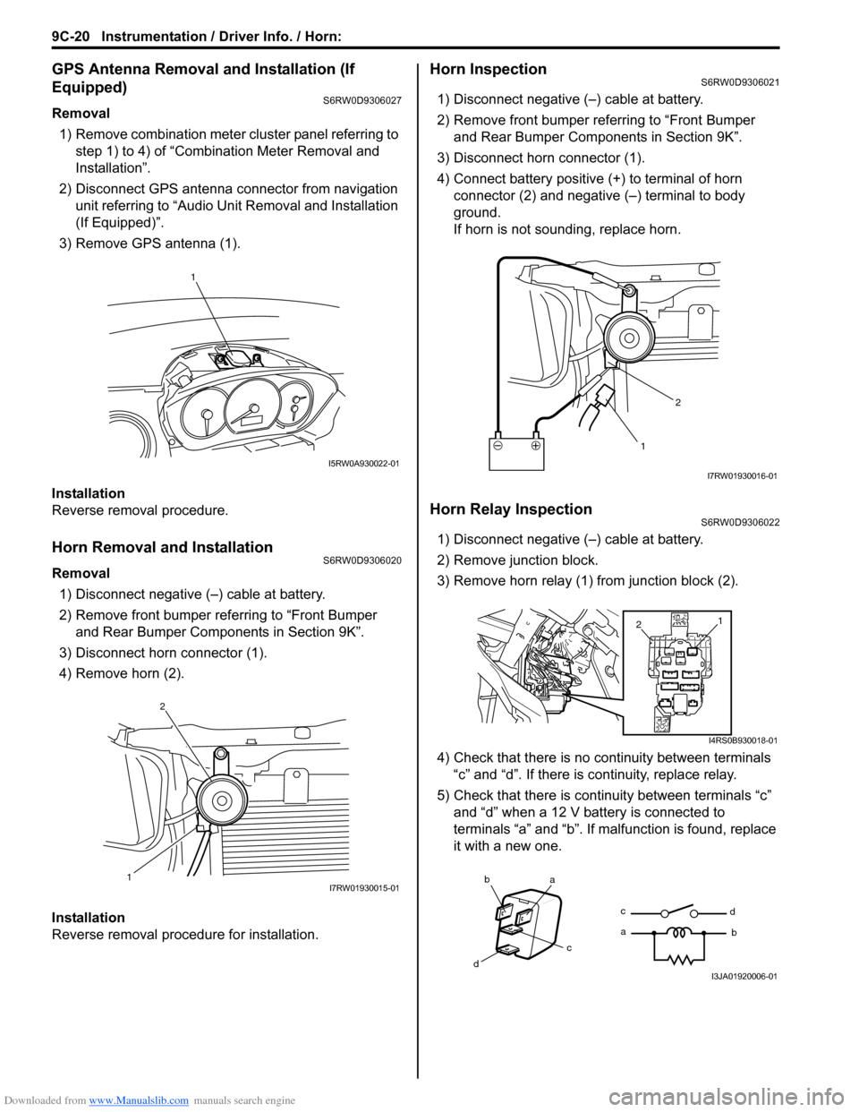
3) Remove GPS antenna (1).
Installation
Reverse removal procedure.
Horn Removal and InstallationS6RW0D9306020
Removal
1) Disconnect negative (–) cable at battery.
2) Remove front bumper referring to “Front Bumper
and Rear Bumper Components in Section 9K”.
3) Disconnect horn connector (1).
4) Remove horn (2).
Installation
Reverse removal procedure for installation.
Horn InspectionS6RW0D9306021
1) Disconnect negative (–) cable at battery.
2) Remove front bumper referring to “Front Bumper
and Rear Bumper Components in Section 9K”.
3) Disconnect horn connector (1).
4) Connect battery positive (+) to terminal of horn
connector (2) and negative (–) terminal to body
ground.
If horn is not sounding, replace horn.
Horn Relay InspectionS6RW0D9306022
1) Disconnect negative (–) cable at battery.
2) Remove junction block.
3) Remove horn relay (1) from junction block (2).
4) Check that there is no continuity between terminals
“c” and “d”. If there is continuity, replace relay.
5) Check that there is continuity between terminals “c”
and “d” when a 12 V battery is connected to
terminals “a” and “b”. If malfunction is found, replace
it with a new one.
1
I5RW0A930022-01
12I7RW01930015-01
12
I7RW01930016-01
1
2
I4RS0B930018-01
ba
c
dc
ad
bI3JA01920006-01
Page 1373 of 1556
Downloaded from www.Manualslib.com manuals search engine Instrumentation / Driver Info. / Horn: 9C-21
Antenna Base Removal and InstallationS6RW0D9306023
Removal
1) Remove head lining referring to “Head Lining
Removal and Installation in Section 9H”.
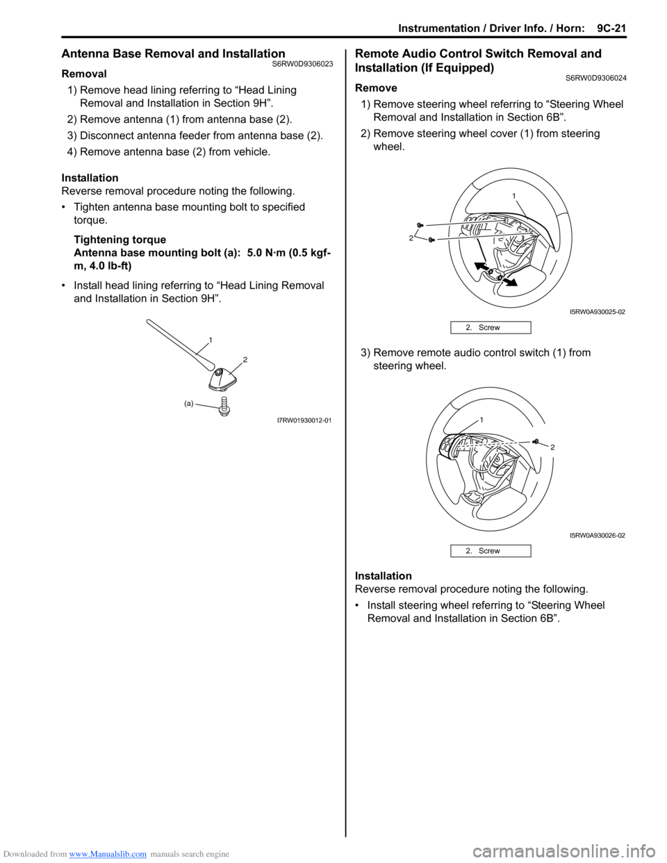
2) Remove antenna (1) from antenna base (2).
3) Disconnect antenna feeder from antenna base (2).
4) Remove antenna base (2) from vehicle.
Installation
Reverse removal procedure noting the following.
• Tighten antenna base mounting bolt to specified
torque.
Tightening torque
Antenna base mounting bolt (a): 5.0 N·m (0.5 kgf-
m, 4.0 lb-ft)
• Install head lining referring to “Head Lining Removal
and Installation in Section 9H”.
Remote Audio Control Switch Removal and
Installation (If Equipped)
S6RW0D9306024
Remove
1) Remove steering wheel referring to “Steering Wheel
Removal and Installation in Section 6B”.
2) Remove steering wheel cover (1) from steering
wheel.
3) Remove remote audio control switch (1) from
steering wheel.
Installation
Reverse removal procedure noting the following.
• Install steering wheel referring to “Steering Wheel
Removal and Installation in Section 6B”.
(a)1
2
I7RW01930012-01
2. Screw
2. Screw
2
1
I5RW0A930025-02
1
2
I5RW0A930026-02
Page 1374 of 1556
Downloaded from www.Manualslib.com manuals search engine 9C-22 Instrumentation / Driver Info. / Horn:
Remote Audio Control Switch Inspection (If
Equipped)
S6RW0D9306025
1) Remove driver air bag (inflator) module referring to
“Driver Air Bag (Inflator) Module Removal and
Installation in Section 8B”.
2) Disconnect remote audio control switch connector
from contact coil.
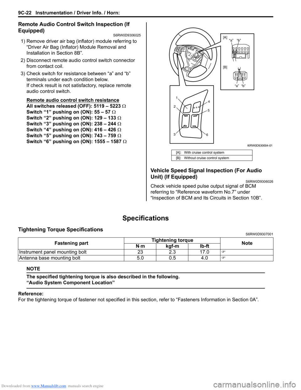
3) Check switch for resistance between “a” and “b”
terminals under each condition below.
If check result is not satisfactory, replace remote
audio control switch.
Remote audio control switch resistance
All switches released (OFF): 5119 – 5223 Ω
Switch “1” pushing on (ON): 55 – 57 Ω
Switch “2” pushing on (ON): 129 – 133 Ω
Switch “3” pushing on (ON): 238 – 244 Ω
Switch “4” pushing on (ON): 416 – 426 Ω
Switch “5” pushing on (ON): 743 – 759 Ω
Switch “6” pushing on (ON): 1555 – 1587 Ω
Vehicle Speed Signal Inspection (For Audio
Unit) (If Equipped)
S6RW0D9306026
Check vehicle speed pulse output signal of BCM
referring to “Reference waveform No.7” under
“Inspection of BCM and Its Circuits in Section 10B”.
Specifications
Tightening Torque SpecificationsS6RW0D9307001
NOTE
The specified tightening torque is also described in the following.
“Audio System Component Location”
Reference:
For the tightening torque of fastener not specified in this section, refer to “Fasteners Information in Section 0A”.
[A]: With cruise control system
[B]: Without cruise control system
1
2
34
5
6
“b” “a”
“b” “a” [A]
[B]
I6RW0D930004-01
Fastening partTightening torque
Note
N⋅mkgf-mlb-ft
Instrument panel mounting bolt 23 2.3 17.0�)
Antenna base mounting bolt 5.0 0.5 4.0�)
Page 1405 of 1556
Downloaded from www.Manualslib.com manuals search engine Glass / Windows / Mirrors: 9E-20
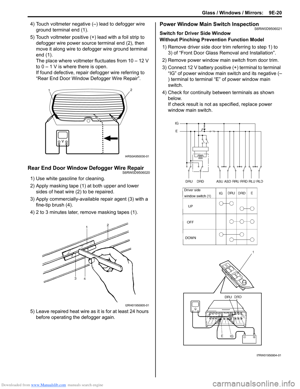
4) Touch voltmeter negative (–) lead to defogger wire
ground terminal end (1).
5) Touch voltmeter positive (+) lead with a foil strip to
defogger wire power source terminal end (2), then
move it along wire to defogger wire ground terminal
end (1).
The place where voltmeter fluctuates from 10 – 12 V
to 0 – 1 V is where there is open.
If found defective, repair defogger wire referring to
“Rear End Door Window Defogger Wire Repair”.
Rear End Door Window Defogger Wire RepairS6RW0D9506020
1) Use white gasoline for cleaning.
2) Apply masking tape (1) at both upper and lower
sides of heat wire (2) to be repaired.
3) Apply commercially-available repair agent (3) with a
fine-tip brush (4).
4) 2 to 3 minutes later, remove masking tapes (1).
5) Leave repaired heat wire as it is for at least 24 hours
before operating the defogger again.
Power Window Main Switch InspectionS6RW0D9506021
Switch for Driver Side Window
Without Pinching Prevention Function Model
1) Remove driver side door trim referring to step 1) to
3) of “Front Door Glass Removal and Installation”.
2) Remove power window main switch from door trim.
3) Connect 12 V battery positive (+) terminal to terminal
“IG” of power window main switch and its negative (–
) terminal to terminal “E” of power window main
switch.
4) Check for continuity between terminals as shown
below.
If check result is not as specified, replace power
window main switch.
21
I4RS0A950030-01
I2RH01950005-01
I7RW01950004-01
Page 1407 of 1556
Downloaded from www.Manualslib.com manuals search engine Glass / Windows / Mirrors: 9E-22
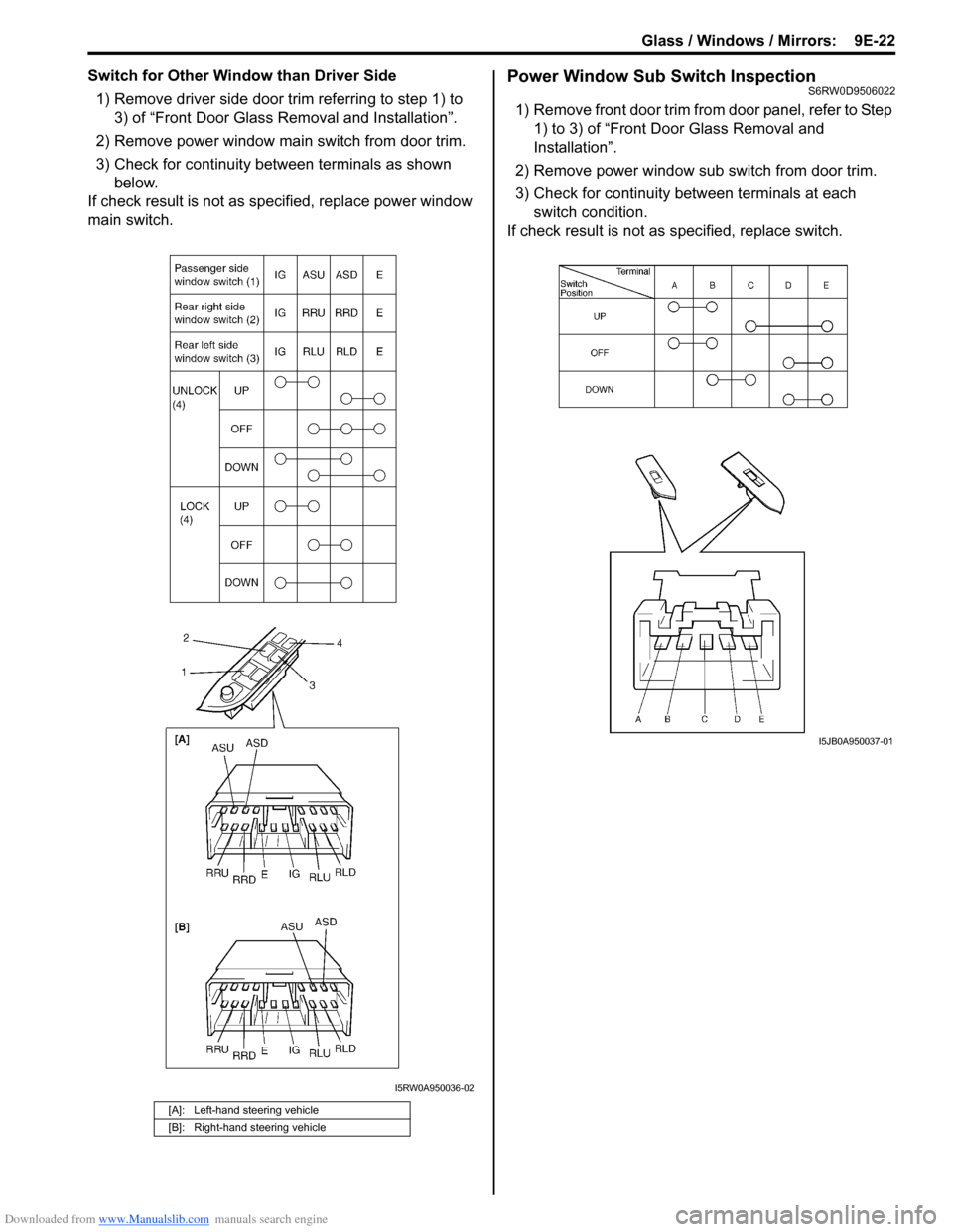
Switch for Other Window than Driver Side
1) Remove driver side door trim referring to step 1) to
3) of “Front Door Glass Removal and Installation”.
2) Remove power window main switch from door trim.
3) Check for continuity between terminals as shown
below.
If check result is not as specified, replace power window
main switch.Power Window Sub Switch InspectionS6RW0D9506022
1) Remove front door trim from door panel, refer to Step
1) to 3) of “Front Door Glass Removal and
Installation”.
2) Remove power window sub switch from door trim.
3) Check for continuity between terminals at each
switch condition.
If check result is not as specified, replace switch.
[A]: Left-hand steering vehicle
[B]: Right-hand steering vehicle
I5RW0A950036-02
I5JB0A950037-01
Page 1408 of 1556
Downloaded from www.Manualslib.com manuals search engine 9E-23 Glass / Windows / Mirrors:
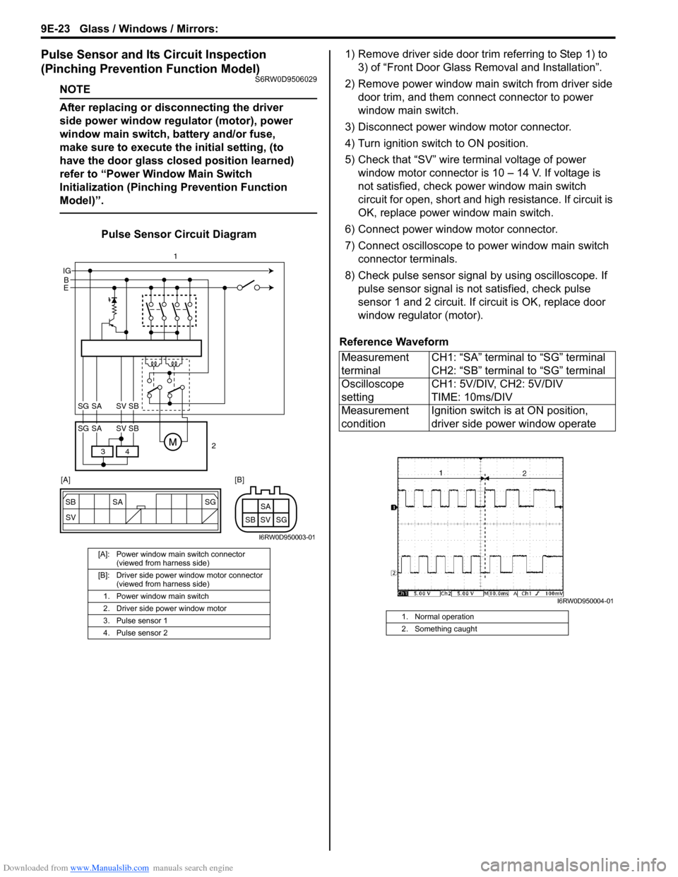
Pulse Sensor and Its Circuit Inspection
(Pinching Prevention Function Model)
S6RW0D9506029
NOTE
After replacing or disconnecting the driver
side power window regulator (motor), power
window main switch, battery and/or fuse,
make sure to execute the initial setting, (to
have the door glass closed position learned)
refer to “Power Window Main Switch
Initialization (Pinching Prevention Function
Model)”.
Pulse Sensor Circuit Diagram1) Remove driver side door trim referring to Step 1) to
3) of “Front Door Glass Removal and Installation”.
2) Remove power window main switch from driver side
door trim, and them connect connector to power
window main switch.
3) Disconnect power window motor connector.
4) Turn ignition switch to ON position.
5) Check that “SV” wire terminal voltage of power
window motor connector is 10 – 14 V. If voltage is
not satisfied, check power window main switch
circuit for open, short and high resistance. If circuit is
OK, replace power window main switch.
6) Connect power window motor connector.
7) Connect oscilloscope to power window main switch
connector terminals.
8) Check pulse sensor signal by using oscilloscope. If
pulse sensor signal is not satisfied, check pulse
sensor 1 and 2 circuit. If circuit is OK, replace door
window regulator (motor).
Reference Waveform
[A]: Power window main switch connector
(viewed from harness side)
[B]: Driver side power window motor connector
(viewed from harness side)
1. Power window main switch
2. Driver side power window motor
3. Pulse sensor 1
4. Pulse sensor 2
SG
SV SB SA
SG SV SBSA
B IG
E
4 3
SG SV SBSA
SG SV SBSA
2 1
[A] [B]
I6RW0D950003-01
Measurement
terminalCH1: “SA” terminal to “SG” terminal
CH2: “SB” terminal to “SG” terminal
Oscilloscope
settingCH1: 5V/DIV, CH2: 5V/DIV
TIME: 10ms/DIV
Measurement
conditionIgnition switch is at ON position,
driver side power window operate
1. Normal operation
2. Something caught
I6RW0D950004-01
Page 1409 of 1556
Downloaded from www.Manualslib.com manuals search engine Glass / Windows / Mirrors: 9E-24
Power Window Main Switch Initialization
(Pinching Prevention Function Model)
S6RW0D9506030
CAUTION!
• After replacing or disconnecting the driver
side door window regulator (motor), power
window main switch, battery or fuse, be
sure to execute initial setting (to have door
glass completely closed position learned).
If initial setting is not executed, correct
automatic operation (including pinching
prevention operation) would not be
available.
• Make sure that no foreign matter is
pinched while executing initial setting.
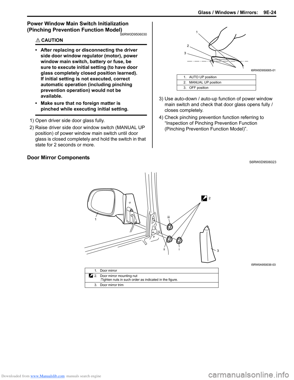
1) Open driver side door glass fully.
2) Raise driver side door window switch (MANUAL UP
position) of power window main switch until door
glass is closed completely and hold the switch in that
state for 2 seconds or more.3) Use auto-down / auto-up function of power window
main switch and check that door glass opens fully /
closes completely.
4) Check pinching prevention function referring to
“Inspection of Pinching Prevention Function
(Pinching Prevention Function Model)”.
Door Mirror ComponentsS6RW0D9506023 1. AUTO UP position
2. MANUAL UP position
3. OFF position
1
2
3
I6RW0D950005-01
2
1
i
iiiii
3
I5RW0A950038-03
1. Door mirror
2. Door mirror mounting nut
:Tighten nuts in such order as indicated in the figure.
3. Door mirror trim
Page 1410 of 1556
Downloaded from www.Manualslib.com manuals search engine 9E-25 Glass / Windows / Mirrors:
Door Mirror Removal and InstallationS6RW0D9506024
When removing or installing door mirror, refer to the
figure in “Door Mirror Components”.
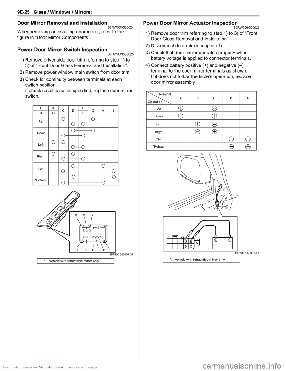
Power Door Mirror Switch InspectionS6RW0D9506025
1) Remove driver side door trim referring to step 1) to
3) of “Front Door Glass Removal and Installation”.
2) Remove power window main switch from door trim.
3) Check for continuity between terminals at each
switch position.
If check result is not as specified, replace door mirror
switch.
Power Door Mirror Actuator InspectionS6RW0D9506026
1) Remove door trim referring to step 1) to 3) of “Front
Door Glass Removal and Installation”.
2) Disconnect door mirror coupler (1).
3) Check that door mirror operates properly when
battery voltage is applied to connector terminals.
4) Connect battery positive (+) and negative (–)
terminal to the door mirror terminals as shown.
If it does not follow the table’s operation, replace
door mirror assembly.
*: Vehicle with retractable mirror only
ABC
DEFG
A
BC
DE
FG
Up
Down
Left
Right
L
RH
I
*Set
*Retract
HII5RS0C950004-01
*: Vehicle with retractable mirror only
A
B
C1 Operation
Terminal
Up
Down
Left
Right
*Set
*RetractCDE B A
D
E
I6RW0D950007-01