2006 SUZUKI SX4 throttle position sensor
[x] Cancel search: throttle position sensorPage 683 of 1556

Downloaded from www.Manualslib.com manuals search engine Automatic Transmission/Transaxle: 5A-35
Poor 2 → 3 shiftShift solenoid valve-A circuit faultyInspect circuit for open, short and intermittent.
If NG, repair.
Output shaft speed sensor (VSS) circuit
faulty Inspect circuit for open, short and intermittent.
If NG, repair.
Transmission range sensor circuit faultyInspect circuit for open, short and intermittent.
If NG, repair.
CAN communication circuit faultyInspect circuit for open, short and intermittent.
If NG, repair.
Throttle position sensor circuit faultyInspect circuit for open, short and intermittent
referring to “DTC P0122: Throttle Position
Sensor (Main) Circuit Low in Section 1A” and/
or “DTC P0123: Throttle Position Sensor
(Main) Circuit High in Section 1A”. If NG, repair.
TCMSubstitute a known-good TCM and recheck.
ECMSubstitute a known-good ECM and recheck.
Poor 3
→ 4 shiftShift solenoid valve-B circuit faultyInspect circuit for open, short and intermittent.
If NG, repair.
Pressure control solenoid valve circuit
faultyInspect circuit for open, short and intermittent.
If NG, repair.
Timing solenoid valve circuit faultyInspect circuit for open, short and intermittent.
If NG, repair.
Output shaft speed sensor (VSS) circuit
faulty Inspect circuit for open, short and intermittent.
If NG, repair.
Input shaft speed sensor circuit faulty Inspect circuit for open, short and intermittent.
If NG, repair.
Transmission range sensor circuit faultyInspect circuit for open, short and intermittent.
If NG, repair.
Transmission fluid temperature sensor
circuit faultyInspect circuit for open, short and intermittent.
If NG, repair.
CAN communication circuit faultyInspect circuit for open, short and intermittent.
If NG, repair.
Throttle position sensor circuit faultyInspect circuit for open, short and intermittent
referring to “DTC P0122: Throttle Position
Sensor (Main) Circuit Low in Section 1A” and/
or “DTC P0123: Throttle Position Sensor
(Main) Circuit High in Section 1A”. If NG, repair.
Engine coolant temperature sensor
circuit faultyInspect circuit for open, short and intermittent
referring to “DTC P0117: Engine Coolant
Temperature Circuit Low in Section 1A” and/or
“DTC P0118: Engine Coolant Temperature
Circuit High in Section 1A”. If NG, repair.
Crankshaft position sensor circuit faultyInspect circuit for open, short and intermittent
referring to “DTC P0335: Crankshaft Position
(CKP) Sensor Circuit in Section 1A”. If NG,
repair.
“3” position switch circuit faultyInspect. If NG, repair.
TCMSubstitute a known-good TCM and recheck.
ECMSubstitute a known-good ECM and recheck. Condition Possible cause Correction / Reference Item
Page 684 of 1556

Downloaded from www.Manualslib.com manuals search engine 5A-36 Automatic Transmission/Transaxle:
Poor 4 → 3 shiftShift solenoid valve-B circuit faultyInspect circuit for open, short and intermittent.
If NG, repair.
Pressure control solenoid valve circuit
faultyInspect circuit for open, short and intermittent.
If NG, repair.
Timing solenoid valve circuit faultyInspect circuit for open, short and intermittent.
If NG, repair.
Output shaft speed sensor (VSS) circuit
faulty Inspect circuit for open, short and intermittent.
If NG, repair.
Input shaft speed sensor circuit faulty Inspect circuit for open, short and intermittent.
If NG, repair.
CAN communication circuit faultyInspect circuit for open, short and intermittent.
If NG, repair.
Throttle position sensor circuit faultyInspect circuit for open, short and intermittent
referring to “DTC P0122: Throttle Position
Sensor (Main) Circuit Low in Section 1A” and/
or “DTC P0123: Throttle Position Sensor
(Main) Circuit High in Section 1A”. If NG, repair.
“3” position switch circuit faultyInspect. If NG, repair.
TCMSubstitute a known-good TCM and recheck.
ECMSubstitute a known-good ECM and recheck.
Poor 3
→ 2 shiftShift solenoid valve-A circuit faultyInspect circuit for open, short and intermittent.
If NG, repair.
Output shaft speed sensor (VSS) circuit
faulty Inspect circuit for open, short and intermittent.
If NG, repair.
CAN communication circuit faultyInspect circuit for open, short and intermittent.
If NG, repair.
Throttle position sensor circuit faultyInspect circuit for open, short and intermittent
referring to “DTC P0122: Throttle Position
Sensor (Main) Circuit Low in Section 1A” and/
or “DTC P0123: Throttle Position Sensor
(Main) Circuit High in Section 1A”. If NG, repair.
TCMSubstitute a known-good TCM and recheck.
ECMSubstitute a known-good ECM and recheck.
Poor 2
→ 1 shiftShift solenoid valve-A circuit faultyInspect circuit for open, short and intermittent.
If NG, repair.
Output shaft speed sensor (VSS) circuit
faulty Inspect circuit for open, short and intermittent.
If NG, repair.
CAN communication circuit faultyInspect circuit for open, short and intermittent.
If NG, repair.
Throttle position sensor circuit faultyInspect circuit for open, short and intermittent
referring to “DTC P0122: Throttle Position
Sensor (Main) Circuit Low in Section 1A” and/
or “DTC P0123: Throttle Position Sensor
(Main) Circuit High in Section 1A”. If NG, repair.
TCMSubstitute a known-good TCM and recheck.
ECMSubstitute a known-good ECM and recheck.
Incorrect gear shift pointOutput shaft speed sensor (VSS) circuit
faulty Inspect circuit for open, short and intermittent.
If NG, repair.
Pressure control solenoid valve circuit
faultyInspect circuit for open, short and intermittent.
If NG, repair.
CAN communication circuit faultyInspect circuit for open, short and intermittent.
If NG, repair.
Throttle position sensor circuit faultyInspect circuit for open, short and intermittent
referring to “DTC P0122: Throttle Position
Sensor (Main) Circuit Low in Section 1A” and/
or “DTC P0123: Throttle Position Sensor
(Main) Circuit High in Section 1A”. If NG, repair.
TCMSubstitute a known-good TCM and recheck.
ECMSubstitute a known-good ECM and recheck. Condition Possible cause Correction / Reference Item
Page 685 of 1556
Downloaded from www.Manualslib.com manuals search engine Automatic Transmission/Transaxle: 5A-37
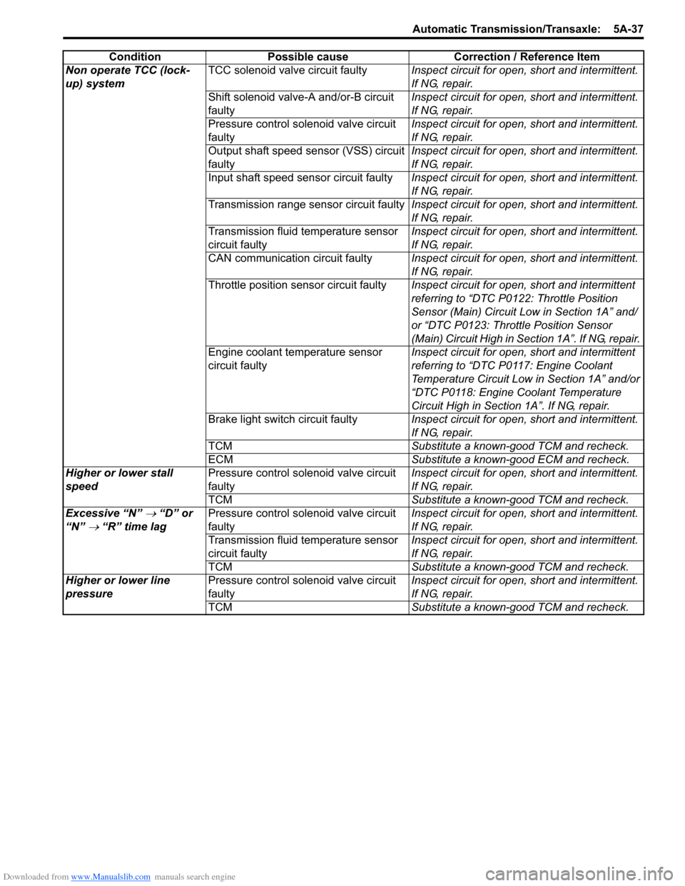
Non operate TCC (lock-
up) systemTCC solenoid valve circuit faultyInspect circuit for open, short and intermittent.
If NG, repair.
Shift solenoid valve-A and/or-B circuit
faultyInspect circuit for open, short and intermittent.
If NG, repair.
Pressure control solenoid valve circuit
faultyInspect circuit for open, short and intermittent.
If NG, repair.
Output shaft speed sensor (VSS) circuit
faulty Inspect circuit for open, short and intermittent.
If NG, repair.
Input shaft speed sensor circuit faulty Inspect circuit for open, short and intermittent.
If NG, repair.
Transmission range sensor circuit faultyInspect circuit for open, short and intermittent.
If NG, repair.
Transmission fluid temperature sensor
circuit faultyInspect circuit for open, short and intermittent.
If NG, repair.
CAN communication circuit faultyInspect circuit for open, short and intermittent.
If NG, repair.
Throttle position sensor circuit faultyInspect circuit for open, short and intermittent
referring to “DTC P0122: Throttle Position
Sensor (Main) Circuit Low in Section 1A” and/
or “DTC P0123: Throttle Position Sensor
(Main) Circuit High in Section 1A”. If NG, repair.
Engine coolant temperature sensor
circuit faultyInspect circuit for open, short and intermittent
referring to “DTC P0117: Engine Coolant
Temperature Circuit Low in Section 1A” and/or
“DTC P0118: Engine Coolant Temperature
Circuit High in Section 1A”. If NG, repair.
Brake light switch circuit faultyInspect circuit for open, short and intermittent.
If NG, repair.
TCMSubstitute a known-good TCM and recheck.
ECMSubstitute a known-good ECM and recheck.
Higher or lower stall
speedPressure control solenoid valve circuit
faultyInspect circuit for open, short and intermittent.
If NG, repair.
TCMSubstitute a known-good TCM and recheck.
Excessive “N”
→ “D” or
“N”
→ “R” time lagPressure control solenoid valve circuit
faultyInspect circuit for open, short and intermittent.
If NG, repair.
Transmission fluid temperature sensor
circuit faultyInspect circuit for open, short and intermittent.
If NG, repair.
TCMSubstitute a known-good TCM and recheck.
Higher or lower line
pressurePressure control solenoid valve circuit
faultyInspect circuit for open, short and intermittent.
If NG, repair.
TCMSubstitute a known-good TCM and recheck. Condition Possible cause Correction / Reference Item
Page 980 of 1556

Downloaded from www.Manualslib.com manuals search engine 7B-40 Air Conditioning System: Automatic Type
HVAC Control DescriptionS6RW0D7221002
Temperature Control
HVAC control module calculates the target temperature
control door position based on signals from the
temperature selector, inside air temperature sensor,
outside air temperature sensor and sunload sensor and
controls the temperature control actuator so that the
current position of the temperature control door matches
its target position.
Fan Speed Control
HVAC control module calculates the target blower fan
speed based on signals from the temperature selector,
inside air temperature sensor, outside air temperature
sensor, ECT sensor and sunload sensor, compares it
with the current blower fan speed inputted from the
blower motor controller to control the current blower fan
speed to the target level.
Air Flow Outlet Control
HVAC control module calculates the target temperature
control door position based on signals from the
temperature selector, inside air temperature sensor,
outside air temperature sensor, ECT sensor and sunload
sensor. Using thus obtained target temperature control
door position, it further calculates the target air flow
control door position and controls the air flow control
actuator so that the current air flow control door position
becomes the target position.
Air Intake Position Control
HVAC control module determines the position of the air
intake control door based on signals from the
temperature selector, inside air temperature sensor,
outside air temperature sensor and sunload sensor and
selects any of the following positions by controlling the
position of the air intake control door.
• FRESH position (FRE)
• RECIRCULATION position (REC)
• MIX position (MIX)A/C Compressor Relay Control
HVAC control module outputs A/C switch ON signal to
ECM via BCM when the vehicle state satisfy conditions
described below.
• A/C switch is ON
• Evaporator temperature is higher than specified value
• Evaporator temperature sensor malfunction is not
detected
Communication of ECM and BCM is established by CAN
(Controller Area Network). (For more detail of CAN
communication, refer to “CAN Communication System
Description in Section 1A”).
ECM turns ON the A/C compressor relay when the
vehicle state satisfy conditions described below.
• A/C switch ON signal is inputted
• A/C refrigerant pressure is within specified range
• Engine speed is within specified range
• Engine coolant temperature is lower than specified
value
• Throttle opening is lower than specified value
• Vehicle is not in either state of starting or quick
acceleration
• ECT sensor malfunction is not detected
• A/C refrigerant pressure sensor malfunction is not
detected
Condenser Cooling Fan Relay Control
ECM turn ON the condenser cooling fan relay at the
same time when ECM turn ON the A/C compressor
relay.
Sub-Cool A/C System DescriptionS6RW0D7221003
Refer to “Sub-Cool A/C System Description”.
Page 1179 of 1556
Downloaded from www.Manualslib.com manuals search engine Wiring Systems: 9A-12
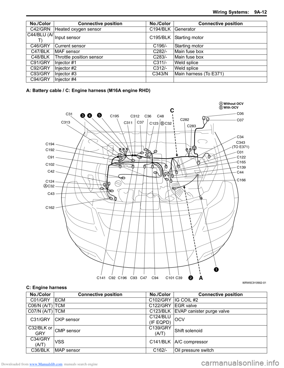
A: Battery cable / C: Engine harness (M16A engine RHD)
C: Engine harnessC42/GRN Heated oxygen sensor C194/BLK Generator
C44/BLU (A/
T)Input sensor C195/BLK Starting motor
C46/GRY Current sensor C196/- Starting motor
C47/BLK MAF sensor C282/- Main fuse box
C48/BLK Throttle position sensor C283/- Main fuse box
C91/GRY Injector #1 C311/- Weld splice
C92/GRY Injector #2 C312/- Weld splice
C93/GRY Injector #3 C343/N Main harness (To E371)
C94/GRY Injector #4 No./Color Connective position No./Color Connective position
C124
C32
C42
C102
C91
C192
C194
C43
C162
C141C196
C195
C93C94C101C39C92
C31
C311C313C312
C36C48
C37C123
C47C32C282
C283
C343
(TO E371)
C01
C34
C07
C06
C122
C165
C139
C44
C166
43
2
1
5C
A
Without OCV
With OCV A
A
B
B
I6RW0C910902-01
No./Color Connective position No./Color Connective position
C01/GRY ECM C102/GRY IG COIL #2
C06/N (A/T) TCM C122/GRY EGR valve
C07/N (A/T) TCM C123/BLK EVAP canister purge valve
C31/GRY CKP sensorC124/BLU
(IF EQPD)OCV
C32/BLK or
GRYCMP sensorC139/GRY
(A/T)Shift solenoid
C34/GRY
(A/T)VSS C141/BLK A/C compressor
C36/BLK MAP sensor C162/- Oil pressure switch
Page 1180 of 1556
Downloaded from www.Manualslib.com manuals search engine 9A-13 Wiring Systems:
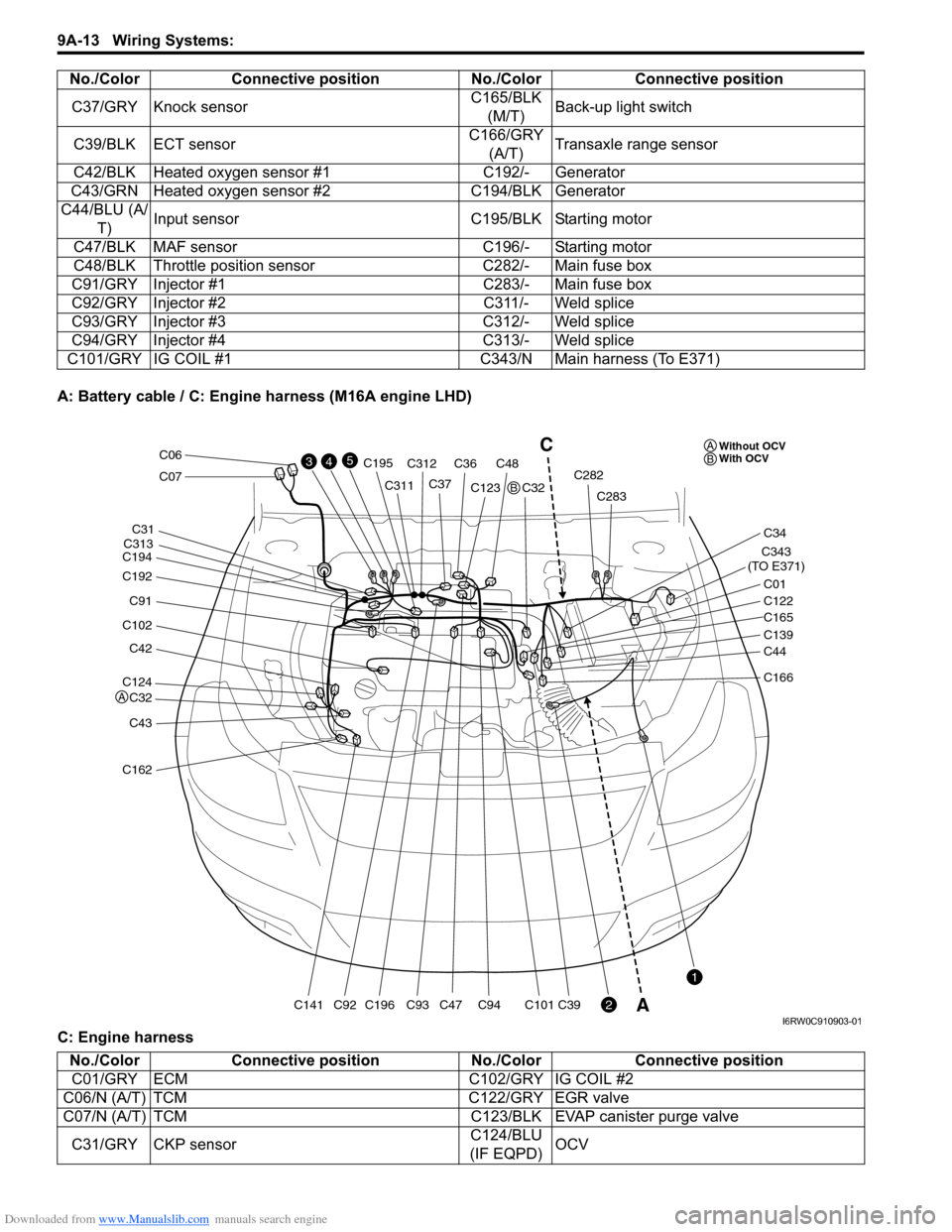
A: Battery cable / C: Engine harness (M16A engine LHD)
C: Engine harnessC37/GRY Knock sensorC165/BLK
(M/T)Back-up light switch
C39/BLK ECT sensorC166/GRY
(A/T)Transaxle range sensor
C42/BLK Heated oxygen sensor #1 C192/- Generator
C43/GRN Heated oxygen sensor #2 C194/BLK Generator
C44/BLU (A/
T)Input sensor C195/BLK Starting motor
C47/BLK MAF sensor C196/- Starting motor
C48/BLK Throttle position sensor C282/- Main fuse box
C91/GRY Injector #1 C283/- Main fuse box
C92/GRY Injector #2 C311/- Weld splice
C93/GRY Injector #3 C312/- Weld splice
C94/GRY Injector #4 C313/- Weld splice
C101/GRY IG COIL #1 C343/N Main harness (To E371)No./Color Connective position No./Color Connective position
C124
C32
C42
C102
C91
C192
C194
C43
C162
C141C196
C195
C93C94C101C39C92
C31
C311
C313C312
C36C48
C37C123
C47C32C282
C283
C343
(TO E371)
C01
C34
C07
C06
C122
C165
C139
C44
C166
43
2
1
5C
AWithout OCV
With OCV A
A
B
B
I6RW0C910903-01
No./Color Connective position No./Color Connective position
C01/GRY ECM C102/GRY IG COIL #2
C06/N (A/T) TCM C122/GRY EGR valve
C07/N (A/T) TCM C123/BLK EVAP canister purge valve
C31/GRY CKP sensorC124/BLU
(IF EQPD)OCV
Page 1181 of 1556
Downloaded from www.Manualslib.com manuals search engine Wiring Systems: 9A-14
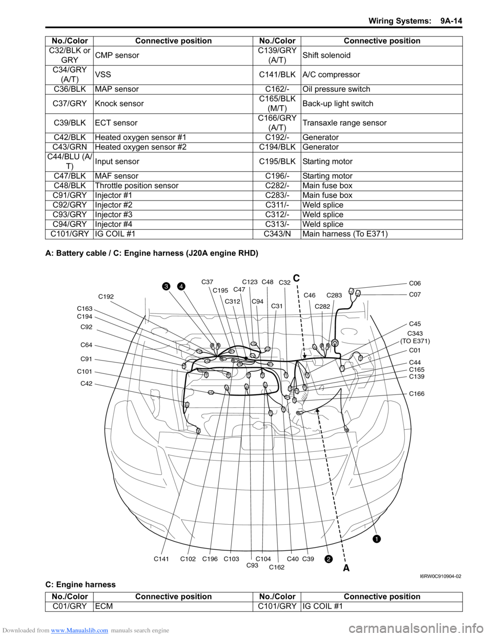
A: Battery cable / C: Engine harness (J20A engine RHD)
C: Engine harnessC32/BLK or
GRYCMP sensorC139/GRY
(A/T)Shift solenoid
C34/GRY
(A/T)VSS C141/BLK A/C compressor
C36/BLK MAP sensor C162/- Oil pressure switch
C37/GRY Knock sensorC165/BLK
(M/T)Back-up light switch
C39/BLK ECT sensorC166/GRY
(A/T)Transaxle range sensor
C42/BLK Heated oxygen sensor #1 C192/- Generator
C43/GRN Heated oxygen sensor #2 C194/BLK Generator
C44/BLU (A/
T)Input sensor C195/BLK Starting motor
C47/BLK MAF sensor C196/- Starting motor
C48/BLK Throttle position sensor C282/- Main fuse box
C91/GRY Injector #1 C283/- Main fuse box
C92/GRY Injector #2 C311/- Weld splice
C93/GRY Injector #3 C312/- Weld splice
C94/GRY Injector #4 C313/- Weld splice
C101/GRY IG COIL #1 C343/N Main harness (To E371)No./Color Connective position No./Color Connective position
C42
C101
C91
C64 C92
C194 C163
C141C102C196 C192
C195
C312
C93C104C103
C94C31C32
C40
C162
C39
C123C48C37
C47
C282
C283C46
C343
(TO E371)
C01
C45
C07
C06
C139 C44
C165
C166
3
2
1
4
A
C
I6RW0C910904-02
No./Color Connective position No./Color Connective position
C01/GRY ECM C101/GRY IG COIL #1
Page 1182 of 1556
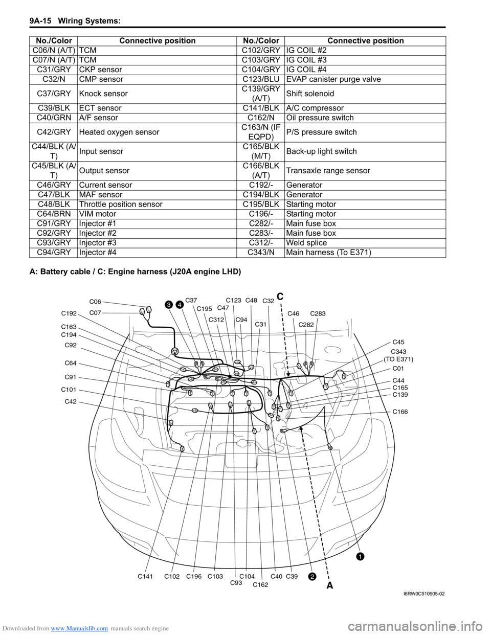
Downloaded from www.Manualslib.com manuals search engine 9A-15 Wiring Systems:
A: Battery cable / C: Engine harness (J20A engine LHD)C06/N (A/T) TCM C102/GRY IG COIL #2
C07/N (A/T) TCM C103/GRY IG COIL #3
C31/GRY CKP sensor C104/GRY IG COIL #4
C32/N CMP sensor C123/BLU EVAP canister purge valve
C37/GRY Knock sensorC139/GRY
(A/T)Shift solenoid
C39/BLK ECT sensor C141/BLK A/C compressor
C40/GRN A/F sensor C162/N Oil pressure switch
C42/GRY Heated oxygen sensorC163/N (IF
EQPD)P/S pressure switch
C44/BLK (A/
T)Input sensorC165/BLK
(M/T)Back-up light switch
C45/BLK (A/
T)Output sensorC166/BLK
(A/T)Transaxle range sensor
C46/GRY Current sensor C192/- Generator
C47/BLK MAF sensor C194/BLK Generator
C48/BLK Throttle position sensor C195/BLK Starting motor
C64/BRN VIM motor C196/- Starting motor
C91/GRY Injector #1 C282/- Main fuse box
C92/GRY Injector #2 C283/- Main fuse box
C93/GRY Injector #3 C312/- Weld splice
C94/GRY Injector #4 C343/N Main harness (To E371) No./Color Connective position No./Color Connective position
C42
C101
C91
C64 C92
C194 C163
C141C102C196 C192
C195
C312
C93C104C103
C94C31C32
C40
C162
C39
C123C48C37
C47
C282
C283C46
C343
(TO E371)
C01
C45
C07
C06
C139 C44
C165
C166
3
2
1
4C
A
I6RW0C910905-02