2006 SUZUKI SX4 temperature sensor
[x] Cancel search: temperature sensorPage 404 of 1556

Downloaded from www.Manualslib.com manuals search engine 1H-9 Ignition System:
2) Start engine and warm it up to normal operating
temperature.
3) Make sure that all of electrical loads except ignition
are switched off.
4) Check to be sure that idle speed is within
specification.
5) Fix ignition timing by using “Fixed Spark Control” of
“Engine / Active Test” mode on scan tool.
6) Set timing light (1) to high-tension cord for No.1
cylinder and check that ignition timing is within
specification.
Initial ignition timing
fixed with SUZUKI scan tool: 5 ± 3° BTDC (at
specified idle speed)
Ignition order
1 – 3 – 4 – 2
Special tool
(A): 09930–764207) If ignition timing is out of specification, check the
followings.
• CKP sensor
• CKP sensor plate
• TP sensor
• CMP sensor
• CMP sensor rotor tooth of camshaft
• Vehicle speed signal from ABS hydraulic unit /
control module
• Knock sensor
• Timing chain cover installation
8) After checking initial ignition timing, release ignition
timing fixation by using scan tool.
9) With engine idling (throttle opening at closed position
and vehicle stopped), check that ignition timing is
about 5° – 15° BTDC (Constant variation within a
few degrees from 5° – 15° BTDC indicates no
abnormality but proves operation of electronic timing
control system.) Also, check that increasing engine
speed advances ignition timing.
If the check results are not satisfactory, check CKP
sensor and ECM.
1, (A)10
0I3RB0A180004-01
Page 477 of 1556

Downloaded from www.Manualslib.com manuals search engine Table of Contents 3- i
3
Section 3
CONTENTS
Driveline / Axle
Precautions ................................................. 3-1
Precautions............................................................. 3-1
Precautions on Driveline / Axle ............................. 3-1
Drive Shaft / Axle ..................................... 3A-1
Front ......................................................................... 3A-1
General Description ............................................. 3A-1
Front Drive Shaft Construction ............................ 3A-1
Component Location ........................................... 3A-1
Front Drive Shaft Assembly Components
Location ............................................................ 3A-1
Diagnostic Information and Procedures ............ 3A-2
Front Drive Shaft Symptom Diagnosis ................ 3A-2
Repair Instructions .............................................. 3A-2
Front Drive Shaft Components ........................... 3A-2
Front Drive Shaft Assembly On-Vehicle
Inspection.......................................................... 3A-3
Front Drive Shaft Assembly Removal and
Installation ......................................................... 3A-3
Front Drive Shaft Disassembly and
Reassembly ...................................................... 3A-4
Center Shaft and Center Bearing Support
Disassembly and Reassembly (If Equipped) .. 3A-12
Specifications..................................................... 3A-13
Tightening Torque Specifications ...................... 3A-13
Special Tools and Equipment ........................... 3A-14
Recommended Service Material ....................... 3A-14
Special Tool ...................................................... 3A-14
Rear ........................................................................ 3A-15
General Description ........................................... 3A-15
Rear Drive Shaft Construction .......................... 3A-15
Repair Instructions ............................................ 3A-15
Rear Drive Shaft Components .......................... 3A-15
Rear Drive Shaft Assembly Removal and
Installation ....................................................... 3A-16
Rear Drive Shaft Disassembly and
Reassembly .................................................... 3A-16
Specifications..................................................... 3A-18
Tightening Torque Specifications ...................... 3A-18
Special Tools and Equipment ........................... 3A-18
Recommended Service Material ....................... 3A-18
Special Tool ...................................................... 3A-18
Differential ................................................ 3B-1
Precautions...........................................................3B-1
Precaution for Rear Differential Oil Leakage....... 3B-1
Precautions in Diagnosing Trouble ..................... 3B-1
General Description .............................................3B-2
Rear Differential Description ............................... 3B-2
Coupling Description ........................................... 3B-2
4WD Control System Components ..................... 3B-3
4WD Control System Description........................ 3B-4
Function of 4WD Control System Component .... 3B-4
4WD Control System Wiring Circuit Diagram...... 3B-5
Terminal Arrangement of 4WD Control
Module .............................................................. 3B-5
Input / Output Signal Table of 4WD Control
Module .............................................................. 3B-6
On-Board Diagnostic System Description ........... 3B-6
CAN Communication System Description........... 3B-7
Diagnostic Information and Procedures ............3B-8
4WD Control System Check ............................... 3B-8
4WD Position Indicator Operation Check.......... 3B-10
4WD Control System Operation Inspection ...... 3B-10
Visual Inspection ............................................... 3B-11
DTC Check........................................................ 3B-11
DTC Clearance ................................................. 3B-11
DTC Table ......................................................... 3B-12
Fail-Safe Table .................................................. 3B-12
Scan Tool Data ................................................. 3B-13
Rear Differential Symptom Diagnosis ............... 3B-14
4WD Control Symptom Diagnosis..................... 3B-14
4WD Position Indicator Does Not Come ON at
Ignition Switch ON but Engine Stops .............. 3B-15
4WD Position Indicator Remains ON Steady
at Ignition Switch ON....................................... 3B-16
DTC C1240: 4WD Control Module Power
Supply Circuit Malfunction............................... 3B-17
DTC C1243: Internal Circuit Malfunction of
4WD Control Module ....................................... 3B-18
DTC C1250: Coupling Air Temperature
Sensor Circuit Open ........................................ 3B-19
DTC C1251: Coupling Air Temperature
Sensor Circuit Short ........................................ 3B-21
DTC C1252: Coupling Assembly Circuit Open .. 3B-22
DTC C1253: Coupling Assembly Circuit Short .. 3B-24
DTC C1254: 2WD/4WD Switch Malfunction ..... 3B-25
DTC U0073: Control Module Communication
Bus Off ............................................................ 3B-27
Page 478 of 1556

Downloaded from www.Manualslib.com manuals search engine 3-ii Table of Contents
DTC U0100: Lost Communication with ECM .... 3B-27
DTC U0121: Lost Communication with ABS /
ESP® Control Module..................................... 3B-27
DTC U0155: Lost Communication with
Instrument Panel Cluster (IPC) Control
Module ............................................................ 3B-27
Inspection of 4WD Control Module and Its
Circuits ............................................................ 3B-27
Repair Instructions ............................................3B-30
Rear Differential Oil Level Check ...................... 3B-30
Rear Differential Oil Change ............................. 3B-30
2WD/4WD Switch Removal and Installation ..... 3B-31
2WD/4WD Switch Inspection ............................ 3B-31
4WD Control Module Removal and
Installation ....................................................... 3B-31
Coupling Air Temperature Sensor Removal
and Installation ................................................ 3B-31
Coupling Air Temperature Sensor Inspection ... 3B-32
Coupling Assembly Inspection .......................... 3B-32
Rear Differential Mountings Components ......... 3B-33
Front Mounting Arm and/or Rear Mounting
Bracket Assembly Removal and Installation ... 3B-34
Rear Mounting Bracket Assembly
Disassembly and Reassembly ........................ 3B-34
Rear Differential Dismounting and
Remounting ..................................................... 3B-34
Rear Differential Components ........................... 3B-35
Rear Differential Disassembly and
Reassembly .................................................... 3B-36
Rear Differential Inspection ............................... 3B-47
Specifications .....................................................3B-48
Tightening Torque Specifications ...................... 3B-48
Special Tools and Equipment ...........................3B-48
Recommended Service Material ....................... 3B-48
Special Tool ...................................................... 3B-49
Transfer .................................................... 3C-1
General Description ............................................. 3C-1
Transfer Description ............................................ 3C-1Diagnostic Information and Procedures ............3C-1
Transfer Symptom Diagnosis..............................3C-1
Repair Instructions ..............................................3C-2
Transfer Oil Level Check.....................................3C-2
Transfer Oil Change ............................................3C-2
Transfer Dismounting and Remounting ..............3C-3
Transfer Assembly Components .........................3C-4
Transfer Assembly Disassembly and
Reassembly ......................................................3C-5
Reduction Drive Gear Assembly Disassembly
and Reassembly ...............................................3C-7
Reduction Driven Gear Assembly
Disassembly and Reassembly ..........................3C-8
Transfer Right Case and Left Case
Disassembly and Reassembly ..........................3C-9
Transfer Output Retainer Assembly
Disassembly and Reassembly ........................3C-10
Transfer Assembly Inspection ...........................3C-14
Bevel Gear Tooth Contact Inspection ...............3C-14
Specifications .....................................................3C-16
Tightening Torque Specifications ......................3C-16
Special Tools and Equipment ...........................3C-17
Recommended Service Material .......................3C-17
Special Tool ......................................................3C-17
Propeller Shafts ....................................... 3D-1
Precautions ...........................................................3D-1
Propeller Shaft Caution .......................................3D-1
General Description .............................................3D-1
Propeller Shaft Construction ...............................3D-1
Diagnostic Information and Procedures ............3D-1
Propeller Shaft Symptom Diagnosis ...................3D-1
Repair Instructions ..............................................3D-2
Propeller Shaft Joint Check.................................3D-2
Propeller Shaft Assembly Removal and
Installation .........................................................3D-2
Propeller Shaft Inspection ...................................3D-2
Specifications .......................................................3D-3
Tightening Torque Specifications ........................3D-3
Page 499 of 1556

Downloaded from www.Manualslib.com manuals search engine Differential: 3B-2
General Description
Rear Differential DescriptionS6RW0D3201001
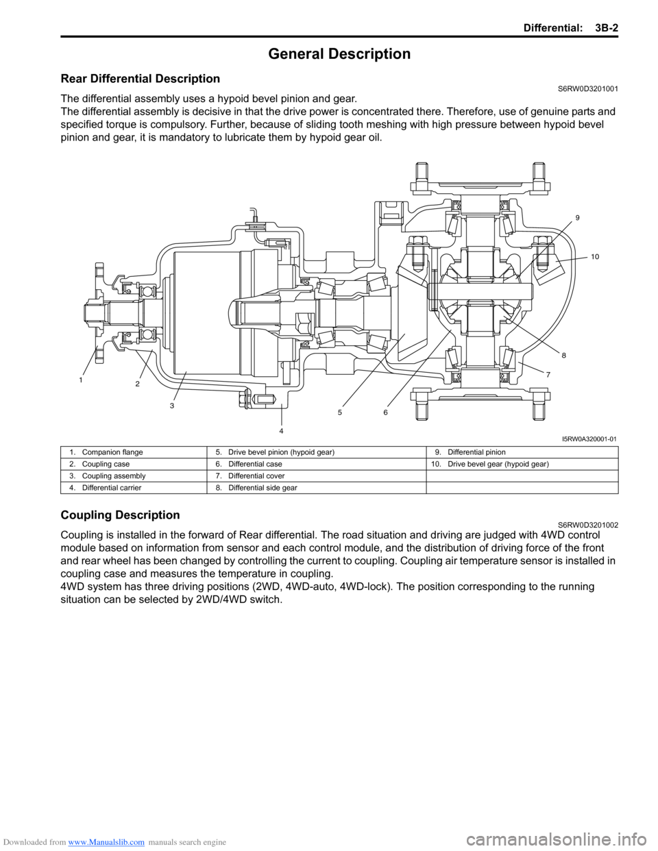
The differential assembly uses a hypoid bevel pinion and gear.
The differential assembly is decisive in that the drive power is concentrated there. Therefore, use of genuine parts and
specified torque is compulsory. Further, because of sliding tooth meshing with high pressure between hypoid bevel
pinion and gear, it is mandatory to lubricate them by hypoid gear oil.
Coupling DescriptionS6RW0D3201002
Coupling is installed in the forward of Rear differential. The road situation and driving are judged with 4WD control
module based on information from sensor and each control module, and the distribution of driving force of the front
and rear wheel has been changed by controlling the current to coupling. Coupling air temperature sensor is installed in
coupling case and measures the temperature in coupling.
4WD system has three driving positions (2WD, 4WD-auto, 4WD-lock). The position corresponding to the running
situation can be selected by 2WD/4WD switch.
1
2
3
4567810 9
I5RW0A320001-01
1. Companion flange 5. Drive bevel pinion (hypoid gear) 9. Differential pinion
2. Coupling case 6. Differential case 10. Drive bevel gear (hypoid gear)
3. Coupling assembly 7. Differential cover
4. Differential carrier 8. Differential side gear
Page 500 of 1556

Downloaded from www.Manualslib.com manuals search engine 3B-3 Differential:
4WD Control System ComponentsS6RW0D3201003
2
1
3
6
5 4
I5RW0A320002-04
1. 4WD control module 3. 4WD LOCK indicator 5. Coupling assembly
2. 4WD AUTO indicator 4. 2WD/4WD switch 6. Coupling air temperature sensor
Page 502 of 1556

Downloaded from www.Manualslib.com manuals search engine 3B-5 Differential:
4WD Control System Wiring Circuit DiagramS6RW0D3201006
Terminal Arrangement of 4WD Control ModuleS6RW0D3201007
5V
5V
12V
G26-3
YEL
GRY
G26-2
G26-22G26-23REDWHT
G26-13
G26-14
G26-12
G26-11
G26-10BLK
WHT/RED
RED/BLK
GRY/YEL
RED/WHT
12V
L102-1
L102-4
1
37
9
10
12
13
14
12V
G26-21BLU
G26-25
G26-24ORN
BRN
5V
28
11
WHT
WHT
WHTWHTWHTWHT
WHT
RED
RED
RED
REDRED
RED
RED
46
5
L174-4BLK/ORNL174-5L174-1
I7RW01320001-01
1. Coupling assembly 6. ECM 11. Data link connector (DLC)
2. Coupling air temperature sensor 7. 4WD control module 12. “IG COIL” fuse
3. Combination meter 8. 2WD/4WD switch 13. “4WD” fuse
4. BCM 9. “4WD” switch 14. Main fuse box
5. ABS / ESP® control module 10. “4WD lock” switch
1 2 3 4 5 6 7 8 9 10 11 12
13 14 15 16 17 18 19 20 21 22 23 24 25 26
[A]
I4JA01332038-01
[A]: Connector “G26” viewed from harness side
Te r m i n a l C i r c u i t Te r m i n a l C i r c u i t
G26-2 Coupling assembly (power) G26-14 “4WD lock” switch
G26-3 Coupling assembly (ground) G26-21 Data link connector (DLC)
G26-10 Ground G26-22 CAN communication line (high)
G26-11 Power source for internal memory G26-23 CAN communication line (low)
G26-12 Power source G26-24 Coupling air temperature sensor (ground)
G26-13 “4WD” switch G26-25 Coupling air temperature sensor (power)
Page 503 of 1556

Downloaded from www.Manualslib.com manuals search engine Differential: 3B-6
Input / Output Signal Table of 4WD Control ModuleS6RW0D3201008
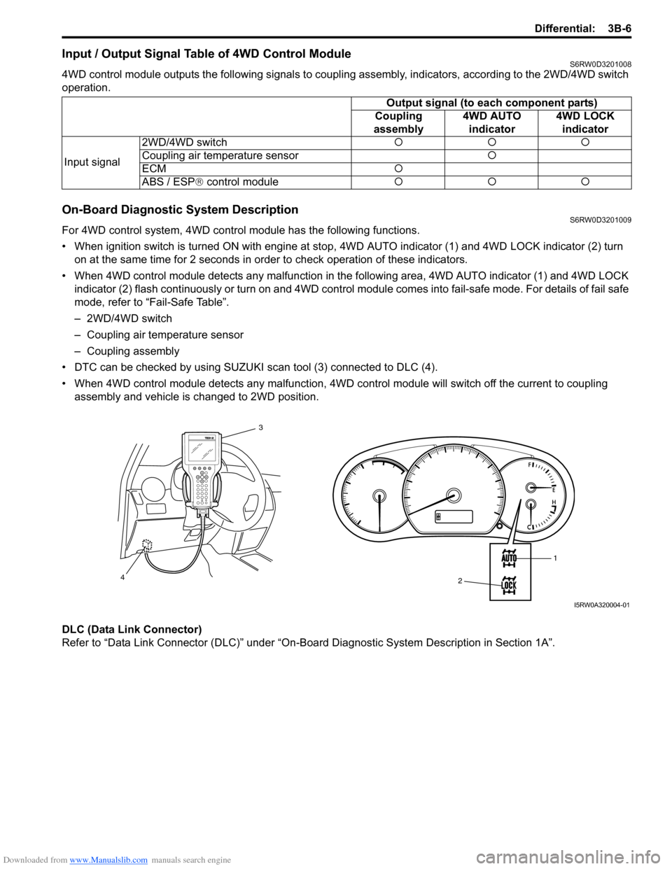
4WD control module outputs the following signals to coupling assembly, indicators, according to the 2WD/4WD switch
operation.
On-Board Diagnostic System DescriptionS6RW0D3201009
For 4WD control system, 4WD control module has the following functions.
• When ignition switch is turned ON with engine at stop, 4WD AUTO indicator (1) and 4WD LOCK indicator (2) turn
on at the same time for 2 seconds in order to check operation of these indicators.
• When 4WD control module detects any malfunction in the following area, 4WD AUTO indicator (1) and 4WD LOCK
indicator (2) flash continuously or turn on and 4WD control module comes into fail-safe mode. For details of fail safe
mode, refer to “Fail-Safe Table”.
– 2WD/4WD switch
– Coupling air temperature sensor
– Coupling assembly
• DTC can be checked by using SUZUKI scan tool (3) connected to DLC (4).
• When 4WD control module detects any malfunction, 4WD control module will switch off the current to coupling
assembly and vehicle is changed to 2WD position.
DLC (Data Link Connector)
Refer to “Data Link Connector (DLC)” under “On-Board Diagnostic System Description in Section 1A”.Output signal (to each component parts)
Coupling
assembly4WD AUTO
indicator4WD LOCK
indicator
Input signal2WD/4WD switch�{�{�{
Coupling air temperature sensor�{
ECM�{
ABS / ESP® control module�{�{�{
1
2 3
4
I5RW0A320004-01
Page 509 of 1556

Downloaded from www.Manualslib.com manuals search engine Differential: 3B-12
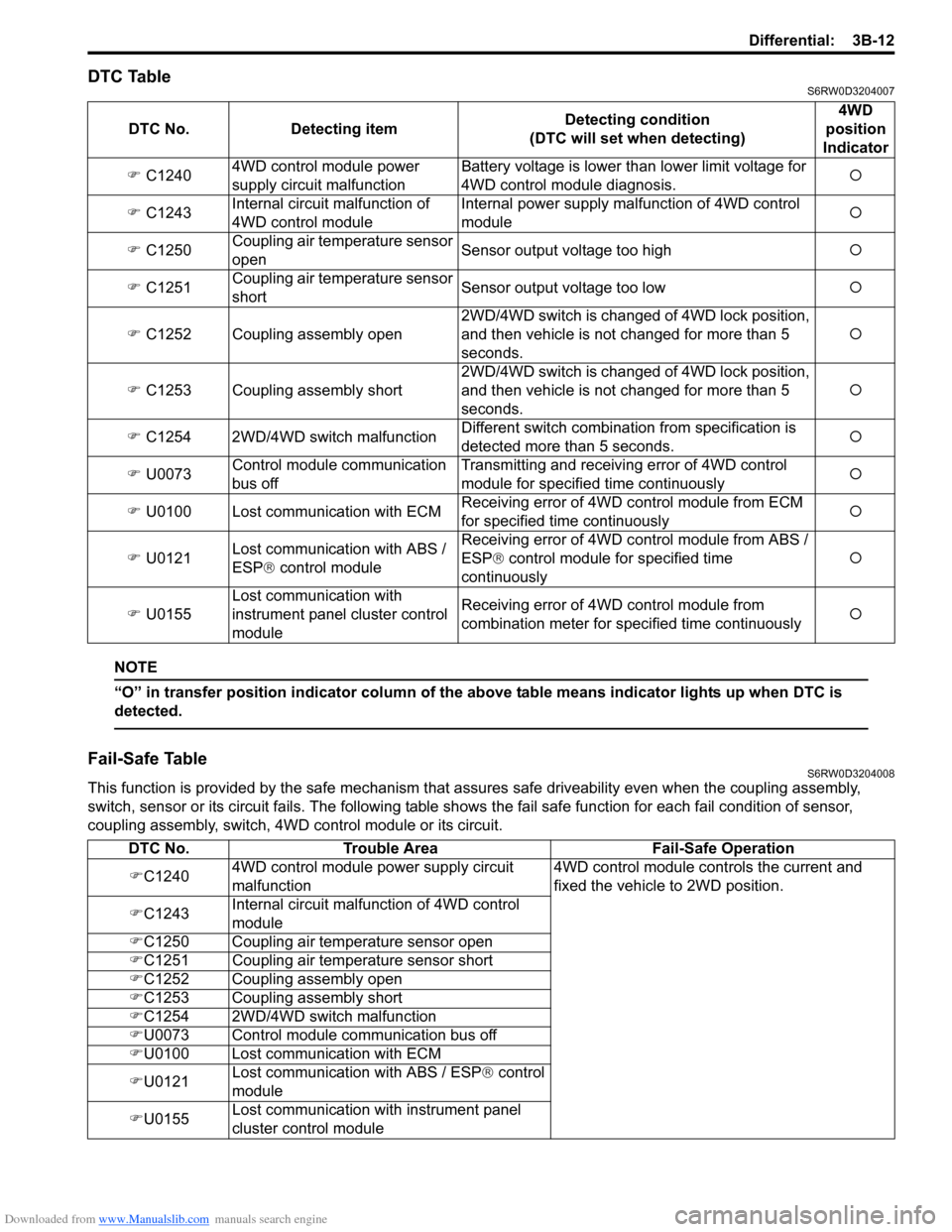
DTC TableS6RW0D3204007
NOTE
“O” in transfer position indicator column of the above table means indicator lights up when DTC is
detected.
Fail-Safe TableS6RW0D3204008
This function is provided by the safe mechanism that assures safe driveability even when the coupling assembly,
switch, sensor or its circuit fails. The following table shows the fail safe function for each fail condition of sensor,
coupling assembly, switch, 4WD control module or its circuit. DTC No. Detecting itemDetecting condition
(DTC will set when detecting)4WD
position
Indicator
�) C12404WD control module power
supply circuit malfunctionBattery voltage is lower than lower limit voltage for
4WD control module diagnosis.�{
�) C1243Internal circuit malfunction of
4WD control moduleInternal power supply malfunction of 4WD control
module�{
�) C1250Coupling air temperature sensor
openSensor output voltage too high�{
�) C1251Coupling air temperature sensor
shortSensor output voltage too low�{
�) C1252 Coupling assembly open2WD/4WD switch is changed of 4WD lock position,
and then vehicle is not changed for more than 5
seconds.�{
�) C1253 Coupling assembly short2WD/4WD switch is changed of 4WD lock position,
and then vehicle is not changed for more than 5
seconds.�{
�) C1254 2WD/4WD switch malfunctionDifferent switch combination from specification is
detected more than 5 seconds.�{
�) U0073Control module communication
bus offTransmitting and receiving error of 4WD control
module for specified time continuously�{
�) U0100 Lost communication with ECMReceiving error of 4WD control module from ECM
for specified time continuously�{
�) U0121Lost communication with ABS /
ESP® control moduleReceiving error of 4WD control module from ABS /
ESP® control module for specified time
continuously�{
�) U0155Lost communication with
instrument panel cluster control
moduleReceiving error of 4WD control module from
combination meter for specified time continuously�{
DTC No. Trouble Area Fail-Safe Operation
�)C12404WD control module power supply circuit
malfunction4WD control module controls the current and
fixed the vehicle to 2WD position.
�)C1243Internal circuit malfunction of 4WD control
module
�)C1250 Coupling air temperature sensor open
�)C1251 Coupling air temperature sensor short
�)C1252 Coupling assembly open
�)C1253 Coupling assembly short
�)C1254 2WD/4WD switch malfunction
�)U0073 Control module communication bus off
�)U0100 Lost communication with ECM
�)U0121Lost communication with ABS / ESP® control
module
�)U0155Lost communication with instrument panel
cluster control module