2006 SUZUKI SX4 oil level
[x] Cancel search: oil levelPage 1189 of 1556
Downloaded from www.Manualslib.com manuals search engine Wiring Systems: 9A-22
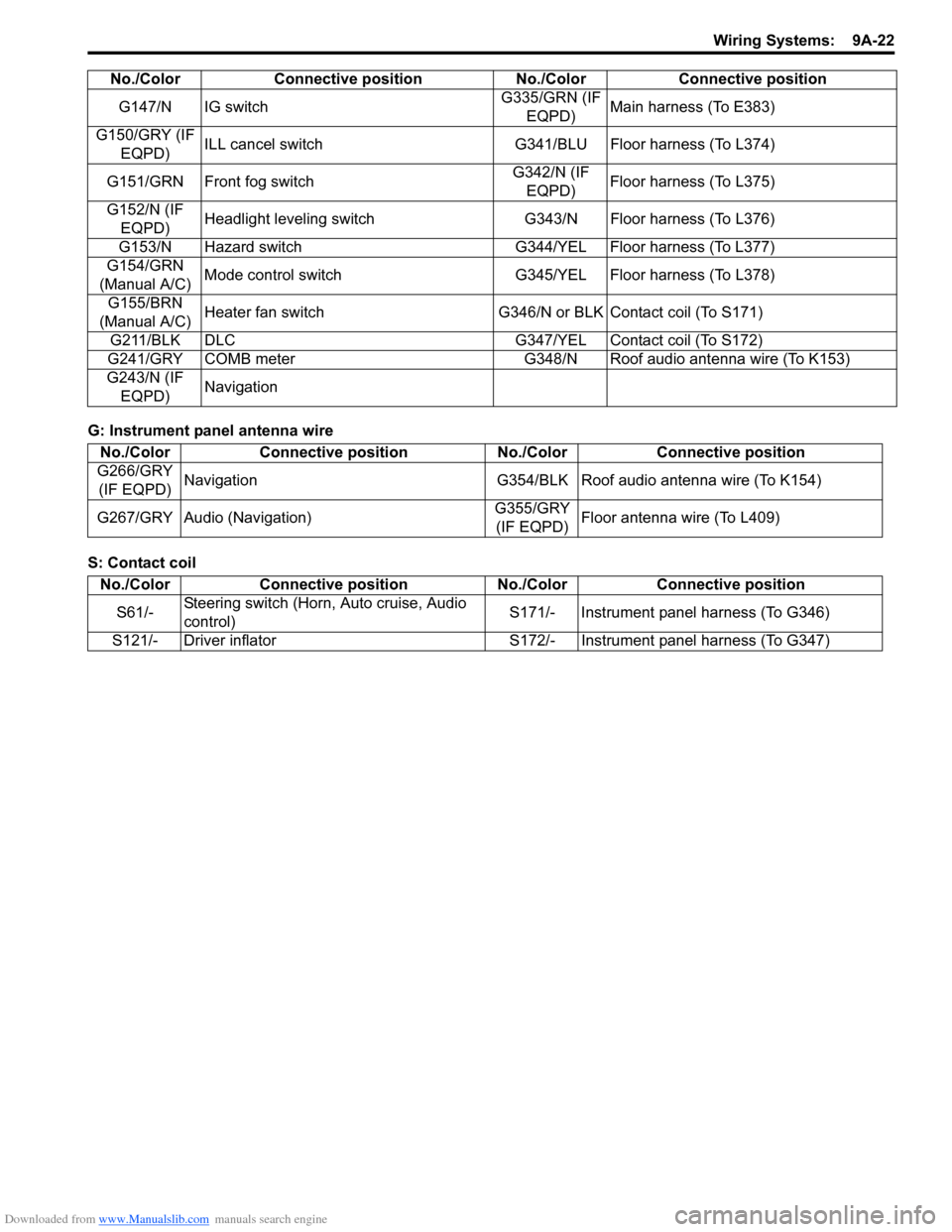
G: Instrument panel antenna wire
S: Contact coilG147/N IG switchG335/GRN (IF
EQPD)Main harness (To E383)
G150/GRY (IF
EQPD)ILL cancel switch G341/BLU Floor harness (To L374)
G151/GRN Front fog switchG342/N (IF
EQPD)Floor harness (To L375)
G152/N (IF
EQPD)Headlight leveling switch G343/N Floor harness (To L376)
G153/N Hazard switch G344/YEL Floor harness (To L377)
G154/GRN
(Manual A/C)Mode control switch G345/YEL Floor harness (To L378)
G155/BRN
(Manual A/C)Heater fan switch G346/N or BLK Contact coil (To S171)
G211/BLK DLC G347/YEL Contact coil (To S172)
G241/GRY COMB meter G348/N Roof audio antenna wire (To K153)
G243/N (IF
EQPD)Navigation No./Color Connective position No./Color Connective position
No./Color Connective position No./Color Connective position
G266/GRY
(IF EQPD)Navigation G354/BLK Roof audio antenna wire (To K154)
G267/GRY Audio (Navigation)G355/GRY
(IF EQPD)Floor antenna wire (To L409)
No./Color Connective position No./Color Connective position
S61/-Steering switch (Horn, Auto cruise, Audio
control)S171/- Instrument panel harness (To G346)
S121/- Driver inflator S172/- Instrument panel harness (To G347)
Page 1191 of 1556
Downloaded from www.Manualslib.com manuals search engine Wiring Systems: 9A-24
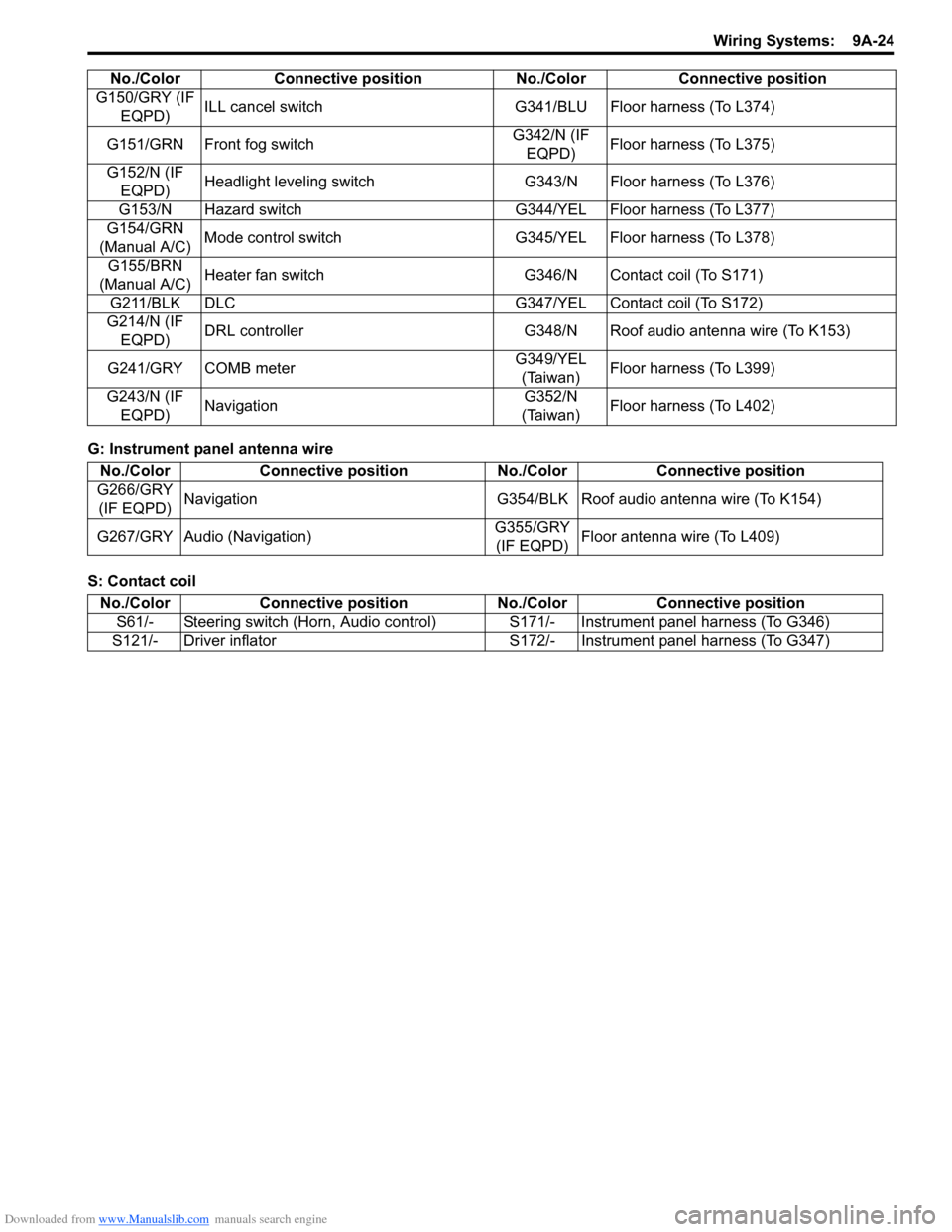
G: Instrument panel antenna wire
S: Contact coilG150/GRY (IF
EQPD)ILL cancel switch G341/BLU Floor harness (To L374)
G151/GRN Front fog switchG342/N (IF
EQPD)Floor harness (To L375)
G152/N (IF
EQPD)Headlight leveling switch G343/N Floor harness (To L376)
G153/N Hazard switch G344/YEL Floor harness (To L377)
G154/GRN
(Manual A/C)Mode control switch G345/YEL Floor harness (To L378)
G155/BRN
(Manual A/C)Heater fan switch G346/N Contact coil (To S171)
G211/BLK DLC G347/YEL Contact coil (To S172)
G214/N (IF
EQPD)DRL controller G348/N Roof audio antenna wire (To K153)
G241/GRY COMB meterG349/YEL
(Taiwan)Floor harness (To L399)
G243/N (IF
EQPD)NavigationG352/N
(Taiwan)Floor harness (To L402) No./Color Connective position No./Color Connective position
No./Color Connective position No./Color Connective position
G266/GRY
(IF EQPD)Navigation G354/BLK Roof audio antenna wire (To K154)
G267/GRY Audio (Navigation)G355/GRY
(IF EQPD)Floor antenna wire (To L409)
No./Color Connective position No./Color Connective position
S61/- Steering switch (Horn, Audio control)S171/- Instrument panel harness (To G346)
S121/- Driver inflator S172/- Instrument panel harness (To G347)
Page 1205 of 1556
Downloaded from www.Manualslib.com manuals search engine Wiring Systems: 9A-38
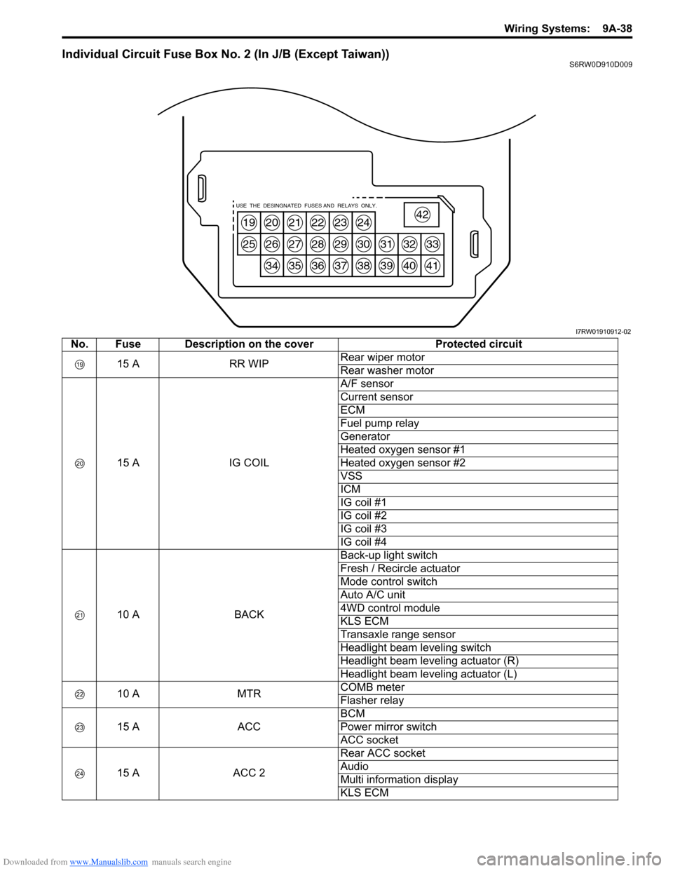
Individual Circuit Fuse Box No. 2 (In J/B (Except Taiwan))S6RW0D910D009
19
25
20
26
34
21
27
35
22
28
36
23
29
37
24
30
38
31
39
32
40
33
41
42USE THE DESINGNATED FUSES AND RELAYS ONLY.
I7RW01910912-02
No. Fuse Description on the cover Protected circuit
15 A RR WIPRear wiper motor
Rear washer motor
15 A IG COILA/F sensor
Current sensor
ECM
Fuel pump relay
Generator
Heated oxygen sensor #1
Heated oxygen sensor #2
VSS
ICM
IG coil #1
IG coil #2
IG coil #3
IG coil #4
10 A BACKBack-up light switch
Fresh / Recircle actuator
Mode control switch
Auto A/C unit
4WD control module
KLS ECM
Transaxle range sensor
Headlight beam leveling switch
Headlight beam leveling actuator (R)
Headlight beam leveling actuator (L)
10 A MTRCOMB meter
Flasher relay
15 A ACCBCM
Power mirror switch
ACC socket
15 A ACC 2Rear ACC socket
Audio
Multi information display
KLS ECM
Page 1247 of 1556
Downloaded from www.Manualslib.com manuals search engine Wiring Systems: 9A-80
15 7
"D-5"
16 BBG0410
BLU/YEL
BLU/YEL
J/C
G308
G146
1 47 4
Main switch
(Key switch)
RHD Flasher relay
DOME
G2715 15A
37ACC MTR
15A23
228
1
12
HORN
-HAZ
15A39
11
10A
22
WHT/RED
WHT/RED
YEL/REDYEL/BLK
1E37
2
Ambient
temperature
sensor
"B-5" Switch
614
1617125
RED/BLUBRN/YELLT GRN/BLKBRNGRY/WHTGRY/RED
Parking
brake
switchSeat
belt
switch
"C-3"
RBBY
115
RED/BLK
BB
Oil
pressure
switchBrake
fluid
level
switch
GRB
L01 L01E04
10E048
LgBBGWGR
Main switch
"B-5"
Sub switch
"B-5"
Front door
switch
Front door
switch
"D-5"
BRBR
BLK/BLUBLK/RED
BLK/REDBLK/REDBLK/RED
J/B
FF
Rear door
switch
"D-5"
BR
DD
J/CJ/C
L346
L347
AA
J/C
G307
BCM
GRY
J/B side connector (BCM) A
A
I6RW0C910952-02
Page 1251 of 1556
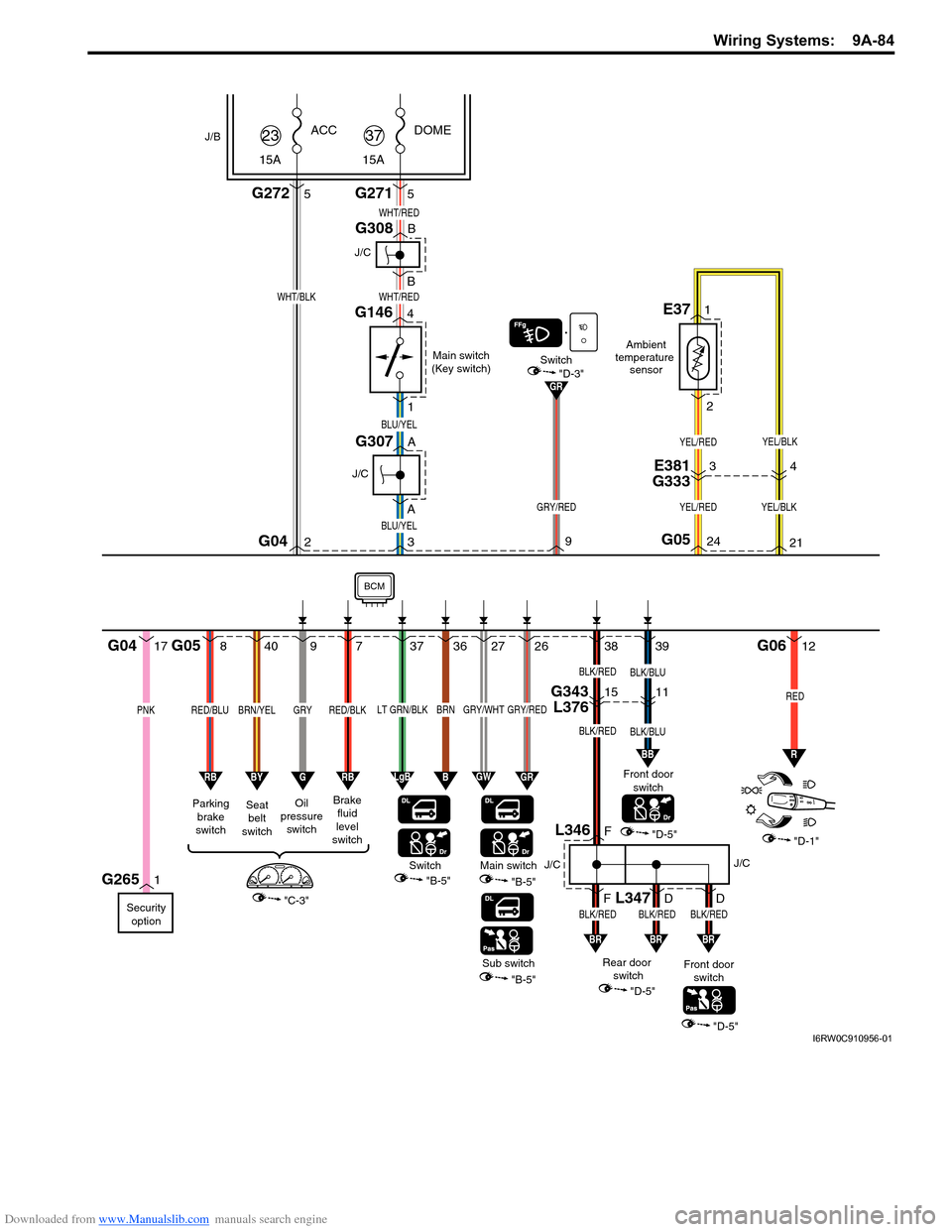
Downloaded from www.Manualslib.com manuals search engine Wiring Systems: 9A-84
38 39
"D-5""D-1"
BLK/BLU
3 AA BBG042
BLU/YEL
BLU/YEL
J/C
G307
1G265
J/C
G308
G146
1 4
Main switch
(Key switch)
DOME
G2715 15A
37ACC
G2725 15A
23
WHT/REDWHT/BLK
WHT/RED
YEL/RED
YEL/RED
YEL/BLK
YEL/BLK
1E37
2
Ambient
temperature
sensor
"B-5" Switch
840
37362726
RED/BLUBRN/YELLT GRN/BLKBRNGRY/WHTGRY/RED
Parking
brake
switchSeat
belt
switch
"C-3"
RBBY
97
RED/BLK
BB
GR
Oil
pressure
switchBrake
fluid
level
switch
Security
option
GRB
G05G0617
PNK
G04
24
GRY/RED
9G0521
LgBBGWGR
Main switch
"B-5"
Sub switch
"B-5"
Front door
switch
"D-3"Switch
Front door
switch
"D-5"
BRBR
BLK/RED
R
12
RED
BLK/BLUBLK/RED
BLK/REDBLK/REDBLK/RED
J/B
FF
Rear door
switch
"D-5"
BR
DD
J/CJ/C
L346
L347
BCM
GRY
E381
G33334
G343
L3761511
I6RW0C910956-01
Page 1273 of 1556
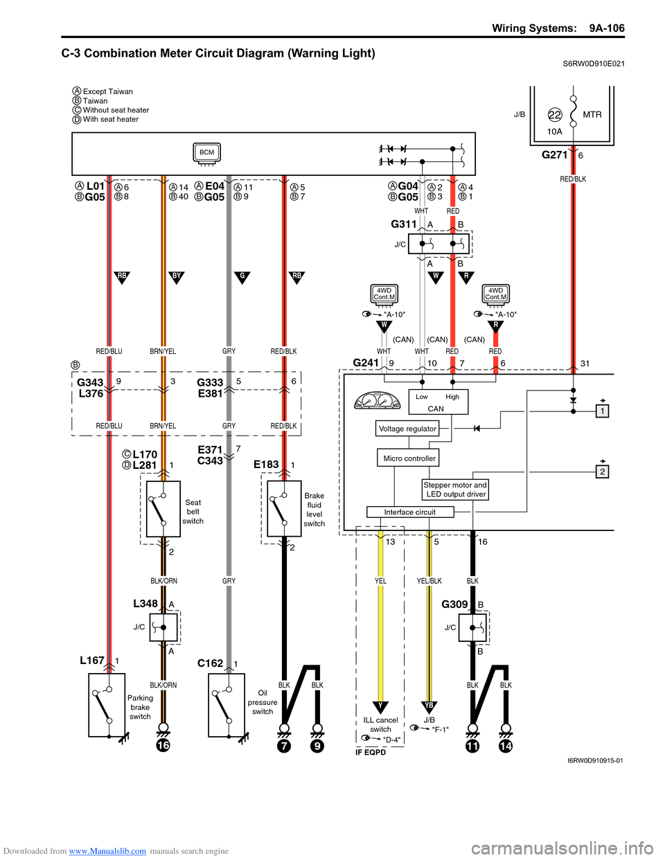
Downloaded from www.Manualslib.com manuals search engine Wiring Systems: 9A-106
C-3 Combination Meter Circuit Diagram (Warning Light)S6RW0D910E021
J/BMTR
10A22
31
Stepper motor and
LED output driver
Voltage regulator
Micro controller
G2716
RED/BLK
516
YB
YEL/BLK
"F-1"
CAN
High Low
WHTWHTRED
RW
10G2419
7
L01
G05
RED/BLUBRN/YEL
L1671
Parking
brake
switch
1
2
A
A
16
BLK/ORN
BLK/ORN
J/C
L348B
B
J/C
G309
Seat
belt
switch
Oil
pressure
switch
J/B
13
Y
YEL
"D-4"
ILL cancel
switch
E371
C3437
G343
L37693G333
E38156
GRY
GRY
1C162
RED/BLK
RED/BLUBRN/YELGRYRED/BLK
E1831
Brake
fluid
level
switch
2
71114
BLK
BLK
BLK
9
BLKBLK
W
WHTRED
1
2
A
AB
B
J/C
G311
RBGBYRB
BCM
"A-10"
4WD
Cont.M
Interface circuit
RED
6
R"A-10"
4WD
Cont.M
(CAN) (CAN) (CAN)
IF EQPD
Except Taiwan
Taiwan
Without seat heater
With seat heater A
A
B
L170
L281C
D
G04
G05A
BE04
G05A
B
BCD
B
6
8AB14
40AB11
9AB5
7AB2
3AB4
1AB
I6RW0D910915-01
Page 1320 of 1556
Downloaded from www.Manualslib.com manuals search engine 9B-1 Lighting Systems:
Body, Cab and Accessories
Lighting Systems
Precautions
Precautions for Discharge Headlight Service (If Equipped)S6RW0D9200001
WARNING!
• Do not touch igniter or ballast when lighting switch is at “HEAD” position to avoid possible electric
shock.
• Do not measure voltage or resistance with tester connected to output connector of ballast or igniter
to avoid possible electric shock.
• Do not perform work where exposed to water including rain or with wet hands to avoid possible
electric shock.
• Disassembling igniter or ballast is strictly prohibited as it may cause an electric shock.
• Before inspecting or repairing discharge headlight or its peripheral parts, make sure that lighting
switch is at OFF position and battery is disconnected at negative terminal to avoid possible
electrical shock.
• Do not set lighting switch to “HEAD” position with connector disconnected or any part removed to
avoid possible electric shock.
• Do not touch glass surface of headlight bulb. Oil or grease attached on it may not only make bulb
service life shorter but also cause bulb to burst when lighting switch is turned on.
• Mercury, metal iodide and xenon gas are sealed in discharge headlight bulb. Be sure to dispose of
used discharge headlight bulb properly according to applicable rules or regulations.
Precautions in Diagnosing Troubles (Headlight Auto Leveling System)S6RW0D9200002
• Be sure to read “Air Bag Warning in Section 00” before inspection and observe what is written there.
• Replacement of height sensor and headlight leveling control module. When height sensor and/or headlight leveling
control module is replaced with new one, perform initialization of headlight auto leveling system according to
“Initialization of Headlight Auto Leveling System”.
General Description
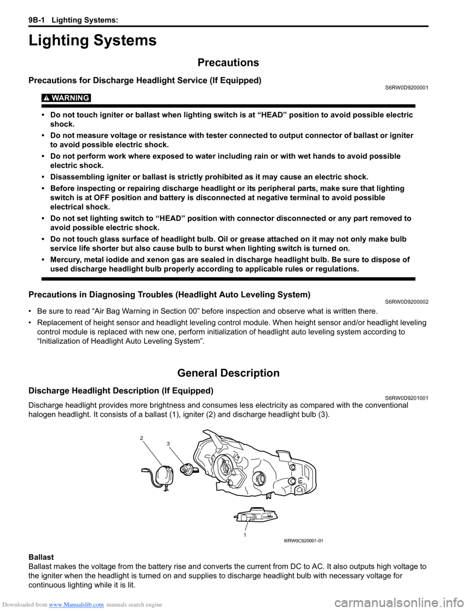
Discharge Headlight Description (If Equipped)S6RW0D9201001
Discharge headlight provides more brightness and consumes less electricity as compared with the conventional
halogen headlight. It consists of a ballast (1), igniter (2) and discharge headlight bulb (3).
Ballast
Ballast makes the voltage from the battery rise and converts the current from DC to AC. It also outputs high voltage to
the igniter when the headlight is turned on and supplies to discharge headlight bulb with necessary voltage for
continuous lighting while it is lit.
2
1 3
I6RW0C920001-01
Page 1329 of 1556
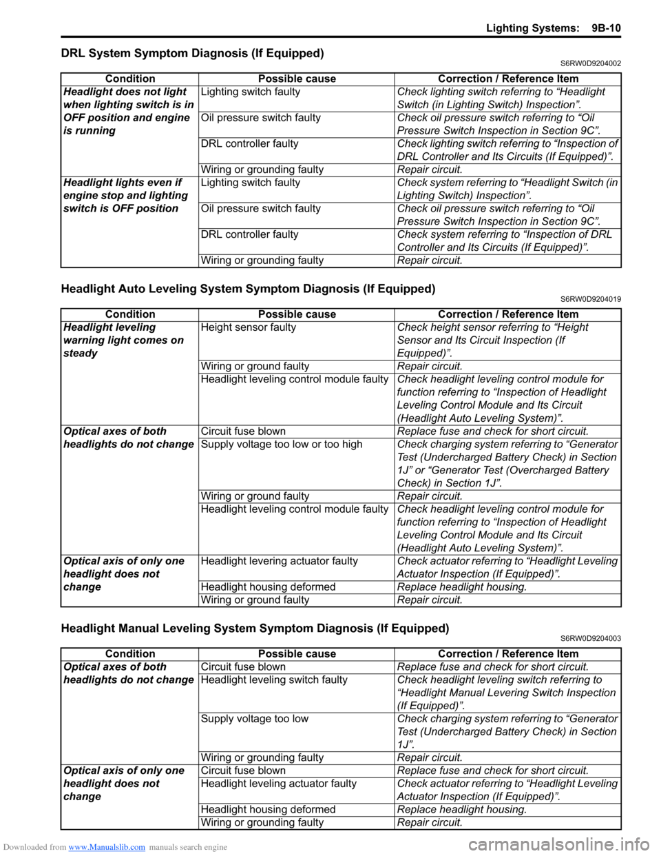
Downloaded from www.Manualslib.com manuals search engine Lighting Systems: 9B-10
DRL System Symptom Diagnosis (If Equipped)S6RW0D9204002
Headlight Auto Leveling System Symptom Diagnosis (If Equipped)S6RW0D9204019
Headlight Manual Leveling System Symptom Diagnosis (If Equipped)S6RW0D9204003
Condition Possible cause Correction / Reference Item
Headlight does not light
when lighting switch is in
OFF position and engine
is runningLighting switch faultyCheck lighting switch referring to “Headlight
Switch (in Lighting Switch) Inspection”.
Oil pressure switch faultyCheck oil pressure switch referring to “Oil
Pressure Switch Inspection in Section 9C”.
DRL controller faultyCheck lighting switch referring to “Inspection of
DRL Controller and Its Circuits (If Equipped)”.
Wiring or grounding faultyRepair circuit.
Headlight lights even if
engine stop and lighting
switch is OFF positionLighting switch faultyCheck system referring to “Headlight Switch (in
Lighting Switch) Inspection”.
Oil pressure switch faultyCheck oil pressure switch referring to “Oil
Pressure Switch Inspection in Section 9C”.
DRL controller faultyCheck system referring to “Inspection of DRL
Controller and Its Circuits (If Equipped)”.
Wiring or grounding faultyRepair circuit.
Condition Possible cause Correction / Reference Item
Headlight leveling
warning light comes on
steadyHeight sensor faultyCheck height sensor referring to “Height
Sensor and Its Circuit Inspection (If
Equipped)”.
Wiring or ground faultyRepair circuit.
Headlight leveling control module faultyCheck headlight leveling control module for
function referring to “Inspection of Headlight
Leveling Control Module and Its Circuit
(Headlight Auto Leveling System)”.
Optical axes of both
headlights do not changeCircuit fuse blownReplace fuse and check for short circuit.
Supply voltage too low or too highCheck charging system referring to “Generator
Test (Undercharged Battery Check) in Section
1J” or “Generator Test (Overcharged Battery
Check) in Section 1J”.
Wiring or ground faultyRepair circuit.
Headlight leveling control module faultyCheck headlight leveling control module for
function referring to “Inspection of Headlight
Leveling Control Module and Its Circuit
(Headlight Auto Leveling System)”.
Optical axis of only one
headlight does not
changeHeadlight levering actuator faultyCheck actuator referring to “Headlight Leveling
Actuator Inspection (If Equipped)”.
Headlight housing deformedReplace headlight housing.
Wiring or ground faultyRepair circuit.
Condition Possible cause Correction / Reference Item
Optical axes of both
headlights do not changeCircuit fuse blownReplace fuse and check for short circuit.
Headlight leveling switch faultyCheck headlight leveling switch referring to
“Headlight Manual Levering Switch Inspection
(If Equipped)”.
Supply voltage too lowCheck charging system referring to “Generator
Test (Undercharged Battery Check) in Section
1J”.
Wiring or grounding faultyRepair circuit.
Optical axis of only one
headlight does not
changeCircuit fuse blownReplace fuse and check for short circuit.
Headlight leveling actuator faultyCheck actuator referring to “Headlight Leveling
Actuator Inspection (If Equipped)”.
Headlight housing deformedReplace headlight housing.
Wiring or grounding faultyRepair circuit.