2006 SUZUKI SX4 oil level
[x] Cancel search: oil levelPage 817 of 1556

Downloaded from www.Manualslib.com manuals search engine Manual Transmission/Transaxle: 5B-5
Diagnostic Information and Procedures
Manual Transaxle Symptom DiagnosisS6RW0D5204001
Repair Instructions
Manual Transaxle Oil Level CheckS6RW0D5206001
1) Lift up vehicle and check oil leakage. Repair leaky
point, if any.
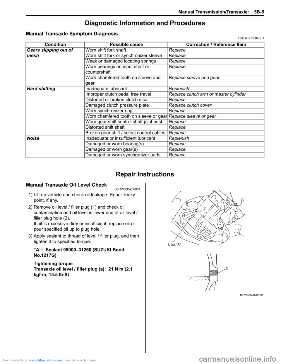
2) Remove oil level / filler plug (1) and check oil
contamination and oil level is lower end of oil level /
filler plug hole (2).
If oil is excessive dirty or insufficient, replace oil or
pour specified oil up to plug hole.
3) Apply sealant to thread of level / filler plug, and then
tighten it to specified torque.
“A”: Sealant 99000–31260 (SUZUKI Bond
No.1217G)
Tightening torque
Transaxle oil level / filler plug (a): 21 N·m (2.1
kgf-m, 15.5 lb-ft)Condition Possible cause Correction / Reference Item
Gears slipping out of
meshWorn shift fork shaftReplace
Worn shift fork or synchronizer sleeveReplace
Weak or damaged locating springsReplace
Worn bearings on input shaft or
countershaftReplace
Worn chamfered tooth on sleeve and
gearReplace sleeve and gear
Hard shiftingInadequate lubricantReplenish
Improper clutch pedal free travelReplace clutch arm or master cylinder
Distorted or broken clutch discReplace
Damaged clutch pressure plateReplace clutch cover
Worn synchronizer ringReplace
Worn chamfered tooth on sleeve or gearReplace sleeve or gear
Worn gear shift control shaft joint bushReplace
Distorted shift shaftReplace
Broken gear shift / select control cablesReplace
NoiseInadequate or insufficient lubricantReplenish
Damaged or worn bearing(s)Replace
Damaged or worn gear(s)Replace
Damaged or worn synchronizer partsReplace
I5RW0A520004-01
Page 818 of 1556

Downloaded from www.Manualslib.com manuals search engine 5B-6 Manual Transmission/Transaxle:
Manual Transaxle Oil ChangeS6RW0D5206002
1) Before changing or inspecting oil, be sure to stop
engine and lift vehicle horizontally.
2) With vehicle lifted up, check leakage.
If leakage exists, correct it.
NOTE
Whenever vehicle is hoisted for any other
service work than oil change, also be sure to
check for oil leakage.
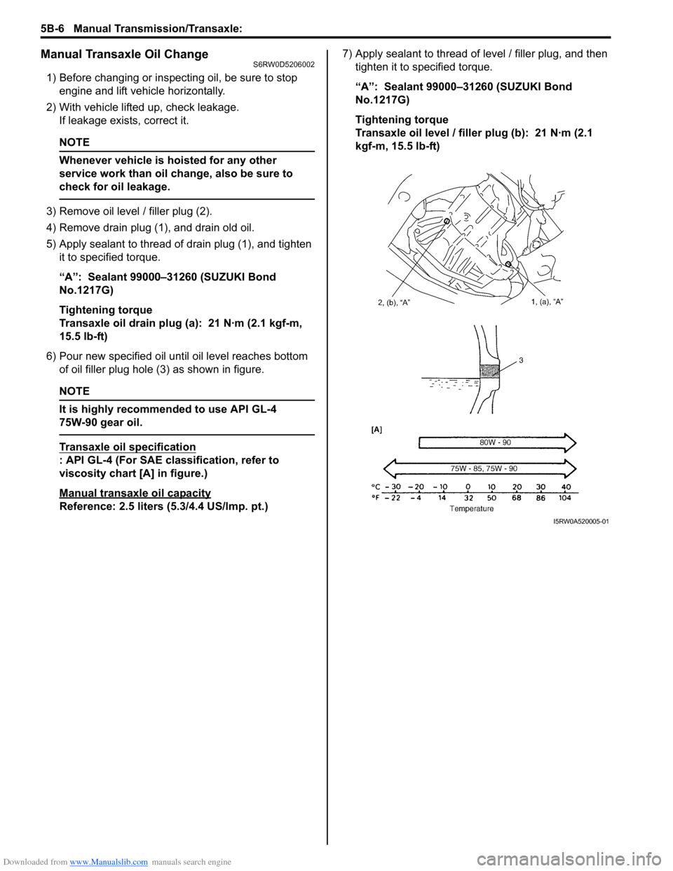
3) Remove oil level / filler plug (2).
4) Remove drain plug (1), and drain old oil.
5) Apply sealant to thread of drain plug (1), and tighten
it to specified torque.
“A”: Sealant 99000–31260 (SUZUKI Bond
No.1217G)
Tightening torque
Transaxle oil drain plug (a): 21 N·m (2.1 kgf-m,
15.5 lb-ft)
6) Pour new specified oil until oil level reaches bottom
of oil filler plug hole (3) as shown in figure.
NOTE
It is highly recommended to use API GL-4
75W-90 gear oil.
Transaxle oil specification
: API GL-4 (For SAE classification, refer to
viscosity chart [A] in figure.)
Manual transaxle oil capacity
Reference: 2.5 liters (5.3/4.4 US/lmp. pt.)7) Apply sealant to thread of level / filler plug, and then
tighten it to specified torque.
“A”: Sealant 99000–31260 (SUZUKI Bond
No.1217G)
Tightening torque
Transaxle oil level / filler plug (b): 21 N·m (2.1
kgf-m, 15.5 lb-ft)
I5RW0A520005-01
Page 828 of 1556

Downloaded from www.Manualslib.com manuals search engine 5B-16 Manual Transmission/Transaxle:
Manual Transaxle Assembly ComponentsS6RW0D5206014
I5RW0A520018-03
1. Transaxle right case 22. Shift fork bolt
: Apply thread lock 99000-32110 to all around thread part of bolt.
2. Transaxle left case
: Apply sealant 99000-31260 to mating surface of left case and right
case.23. 5th gear shift fork
3. Gear shift and select shaft assembly
: Apply sealant 99000-31260 to mating surface of guide case and left
case.24. Needle bearing
4. Transaxle left case plate 25. Input shaft 5th gear
5. Transaxle side cover
: Apply sealant 99000-31260 to mating surface of side cover and left
case.26. Reverse gear shift lever
6. Back up light switch 27. Reverse gear shift lever bolt
: Apply thread lock 99000-32110 to all around thread part of bolt.
7. O-ring28. Reverse gear shaft
8. Differential assembly 29. Washer
9. Oil level / filler plug
: Apply sealant 99000-31260 to all around thread part of plug.30. Reverse idler gear
Page 850 of 1556

Downloaded from www.Manualslib.com manuals search engine 5B-38 Manual Transmission/Transaxle:
4) Press-fit right bearing (1) by using special tools and
hydraulic press.
Special tool
(A): 09925–15410
(B): 09924–07720
(C): 09913–852305) Hold differential assembly with soft jawed vise (3),
install final gear (2) and then tighten new final gear
bolts (1).
CAUTION!
Use of any other bolts than specified ones is
prohibited. Otherwise, bolts may loosen.
Tightening torque
Final gear bolt (a): 90 N·m (9.0 kgf-m, 65.0 lb-ft)
Specifications
Tightening Torque SpecificationsS6RW0D5207001
NOTE
The specified tightening torque is also described in the following.
“Gear Shift Control Lever and Cable Components”
“Manual Transaxle Unit Components”
“Gear Shift and Select Shaft Assembly Components”
“Manual Transaxle Assembly Components”
“Gear Shift Shaft Components”
“Differential Components”
Reference:
For the tightening torque of fastener not specified in this section, refer to “Fasteners Information in Section 0A”.
2. Differential case
3. Differential side left bearing
I5RW0A520048-01I5RW0A520049-01
Fastening partTightening torque
Note
N⋅mkgf-mlb-ft
Transaxle oil level / filler plug 21 2.1 15.5�) / �)
Transaxle oil drain plug 21 2.1 15.5�)
Back up light switch 23 2.3 17.0�)
Guide case bolt No.1 23 2.3 17.0�)
Guide case bolt No.2 23 2.3 17.0�)
Gear shift interlock bolt 23 2.3 17.0�)
5th to reverse interlock guide bolt 23 2.3 17.0�)
Countershaft nut 100 10.0 75.0�)
Shift fork shaft bolt 10 1.0 7.5�)
Side cover bolt 10 1.0 7.5�)
Reverse gear shift lever bolt 23 2.3 17.0�)
Transaxle case bolt 23 2.3 17.0�)
Reverse shaft bolt 23 2.3 17.0�)
Gear shift locating bolt 13 1.3 9.5�)
Left case plate bolt 23 2.3 17.0�)
Oil gutter bolt 10 1.0 7.5�)
Final gear bolt 90 9.0 65.0�)
Page 854 of 1556

Downloaded from www.Manualslib.com manuals search engine 5C-1 Clutch:
Transmission / Transaxle
Clutch
General Description
Clutch (Hydraulic Type) ConstructionS6RW0D5301001
The clutch is a diaphragm spring clutch of a dry single disc type. The diaphragm spring is of a tapering-finger type,
which is a solid ring in the outer diameter part, with a series of tapered fingers pointing inward.
The disc, carrying four torsional coil springs, is positioned on the transaxle input shaft with an involute spline fit.
The clutch cover is secured to the flywheel, and carries the diaphragm spring in such a way that the peripheral edge
part of the spring pushes on the pressure plate against the flywheel (with the disc in between), when the clutch release
bearing (incorporated in clutch operating cylinder) is held back. This is the engaged condition of the clutch.
Depressing the clutch pedal causes the release bearing (incorporated in clutch operating cylinder) to advance and
pushes on the tips of the tapered fingers of the diaphragm spring. When this happens, the diaphragm spring pulls the
pressure plate away from the flywheel, thereby interrupting the flow of drive from flywheel through clutch disc to
transaxle input shaft. Clutch fluid is supplied from brake fluid reservoir. Clutch fluid level can be checked by brake fluid
level of brake fluid reservoir.
I5RW0A530001-01
1. Crankshaft 4. Pressure plate 7. Operating cylinder assembly
2. Flywheel 5. Clutch cover 8. Input shaft bearing
3. Clutch disc 6. Diaphragm spring 9. Input shaft
Page 856 of 1556

Downloaded from www.Manualslib.com manuals search engine 5C-3 Clutch:
Repair Instructions
Clutch Pedal InspectionS6RW0D5306001
Cylinder Push Rod Play “a”
1) Press clutch pedal (1) gradually with finger, stop
when slight increase of resistance is felt and
measure how much pedal has moved (push rod
play) as represented by “a” as shown.
Push rod play
“a”: Max. 3 mm (0.12 in.)
2) If “a” is not within specification, replace master
cylinder (3) or pedal arm (2).
Clutch Pedal Free Travel “b”
1) Depress clutch pedal (1), stop the moment clutch
resistance is felt, and measure how much pedal has
moved (clutch pedal free travel) as represented by
“b” in the figure.
Clutch pedal free travel
“b”
: 2 – 8 mm (0.08 – 0.31 in.)
2) If “b” is not within specification, check pedal arm (2)
and master cylinder (3) and replace defective part.
Clutch Release Margin “c”
1) Pull up parking brake fully and block wheels.
2) Start engine and keep engine at idle with neutral
gear position.
3) Without clutch pedal (1) depressed, slightly push the
shift lever to reverse position until transaxle emits
gear contact noise. Do not shift the lever to reverse
position.
4) With emitting gear contact noise, be slow to depress
clutch pedal (1), and at gear contact noise died
position (release point) stop depressing.
5) Measure distance between release point (4) and full
stroke point (5) on clutch pedal (1) which is shown by
“c” in the figure.
Clutch release margin
“c”: 25 – 55 mm (0.98 – 2.17 in.)6) If “c” is not within specification, it is possible that air
is trapped in this system. If suspected so, bleed air
referring to “Air Bleeding of Clutch System”.Upon
completion of above inspection, start engine and
check clutch for proper operation.
Clutch Fluid Level InspectionS6RW0D5306002
Refer to “Brake Fluid Level Inspection in Section 4A”.
Clutch fluid specification
: Refer to the reservoir cap of the brake master
cylinder.
Air Bleeding of Clutch SystemS6RW0D5306003
CAUTION!
When operating the pedal stroke for air
bleeding of clutch system, after releasing the
clutch pedal, be sure to wait 1 second or
more before depressing it again. Otherwise,
the oil seal of operating cylinder will be
damaged, resulting in oil leakage.
Bleed air from clutch system.
Refer to “Air Bleeding of Brake System in Section 4A”.
I5RW0A530002-01
Page 1163 of 1556

Downloaded from www.Manualslib.com manuals search engine Table of Contents 9-iii
Headlight Bulb Replacement (Discharge
Headlight Model) ............................................. 9B-19
Ballast Removal and Installation (Discharge
Headlight Model) ............................................. 9B-19
Igniter Removal and Installation (Discharge
Headlight Model) ............................................. 9B-20
Headlight Aiming Adjustment with Screen ........ 9B-20
Headlight Switch (in Lighting Switch)
Removal and Installation................................. 9B-22
Headlight Switch (in Lighting Switch)
Inspection........................................................ 9B-22
Hazard Warning Switch Removal and
Installation ....................................................... 9B-23
Hazard Warning Switch Inspection ................... 9B-23
Brake Light Switch Inspection ........................... 9B-23
Turn Signal Light Switch (in Lighting Switch)
Removal and Installation................................. 9B-24
Turn Signal Light Switch (in Lighting Switch)
Inspection........................................................ 9B-24
Turn Signal and Hazard Warning Relay
Removal and Installation................................. 9B-24
Turn Signal and Hazard Warning Relay
Inspection........................................................ 9B-25
License Light Assembly Removal and
Installation ....................................................... 9B-25
Front Fog Light Assembly Removal and
Installation (If Equipped) ................................. 9B-26
Front Fog Light Switch Inspection (If
Equipped)........................................................ 9B-26
Front Fog Light Aiming Adjustment with
Screen (If Equipped) ....................................... 9B-26
Rear Fog Light Switch Inspection (If
Equipped)........................................................ 9B-27
Headlight Manual Levering Switch Inspection
(If Equipped) ................................................... 9B-28
Headlight Leveling Actuator Inspection (If
Equipped)........................................................ 9B-28
Height Sensor Removal and Installation (If
Equipped)........................................................ 9B-29
Height Sensor and Its Circuit Inspection (If
Equipped)........................................................ 9B-30
Headlight Leveling Control Module Removal
and Installation (If Equipped) .......................... 9B-30
Initialization of Headlight Auto Leveling
System ............................................................ 9B-30
Auto-On Headlight Sensor Inspection (If
Equipped)........................................................ 9B-31
Illumination Cancel Switch Inspection (If
Equipped)........................................................ 9B-32
Tail Light Relay, Headlight Relay, Front Fog
Light Relay Inspection (If Equipped) ............... 9B-32
Specifications..................................................... 9B-33
Tightening Torque Specifications ...................... 9B-33
Instrumentation / Driver Info. / Horn ...... 9C-1
Precautions........................................................... 9C-1
Precautions in Diagnosing Troubles for
Combination Meter............................................ 9C-1
General Description ............................................. 9C-1
CAN Communication System Description........... 9C-1Auto Volume Control System Description (If
Equipped) ..........................................................9C-3
Schematic and Routing Diagram ........................9C-4
Combination Meter Circuit Diagram ....................9C-4
Component Location ...........................................9C-5
Audio System Component Location ....................9C-5
Diagnostic Information and Procedures ............9C-6
Speedometer and VSS Symptom Diagnosis ......9C-6
Tachometer Symptom Diagnosis ........................9C-6
Engine Coolant Temperature (ECT) Meter
Symptom Diagnosis ..........................................9C-6
Fuel Meter Symptom Diagnosis ..........................9C-6
Low Fuel Warning Light Symptom Diagnosis .....9C-7
Oil Pressure Warning Light Symptom
Diagnosis ..........................................................9C-7
Brake and Parking Brake Warning Light
Symptom Diagnosis ..........................................9C-8
Seat Belt Reminder Light Symptom Diagnosis ....9C-8
A/T Shift Position Indicator Symptom
Diagnosis (A/T Model).......................................9C-8
Charge Warning Light Symptom Diagnosis ........9C-9
Main Beam (High Beam) Indicator Symptom
Diagnosis ..........................................................9C-9
Warning Buzzer Circuit Symptom Diagnosis ......9C-9
Cigarette Lighter Symptom Diagnosis (If
Equipped) ........................................................9C-10
Horn Symptom Diagnosis .................................9C-10
Information Display Symptom Diagnosis (If
Equipped) ........................................................9C-10
Clock System Diagnosis (If Equipped) ..............9C-11
Audio System Symptom Diagnosis (If
Equipped) ........................................................9C-12
Remote Audio Control Switch Symptom
Diagnosis (If Equipped) ...................................9C-13
Navigation Symptom Diagnosis (If Equipped)...9C-13
Repair Instructions ............................................9C-14
Ignition Switch Removal and Installation...........9C-14
Ignition Switch Inspection..................................9C-14
Combination Meter Removal and Installation ...9C-14
Fuel Level Sensor Removal and Installation .....9C-15
Fuel Level Sensor Inspection ............................9C-15
Oil Pressure Switch Removal and Installation ..9C-15
Oil Pressure Switch Inspection .........................9C-15
Engine Coolant Temperature (ECT) Sensor
Inspection ........................................................9C-16
Brake Fluid Level Switch Inspection .................9C-16
Parking Brake Switch Inspection.......................9C-16
Door Switch (Front / Rear Door) Inspection ......9C-16
Rear End Door Switch Inspection .....................9C-16
Outside Air Temperature Sensor Removal
and Installation (If Equipped) ..........................9C-17
Outside Air Temperature Sensor Inspection
(If Equipped)....................................................9C-17
Instrument Panel Removal and Installation.......9C-17
Information Display (Clock) Removal and
Installation .......................................................9C-18
Audio Unit Removal and Installation (If
Equipped) ........................................................9C-19
Page 1188 of 1556

Downloaded from www.Manualslib.com manuals search engine 9A-21 Wiring Systems:
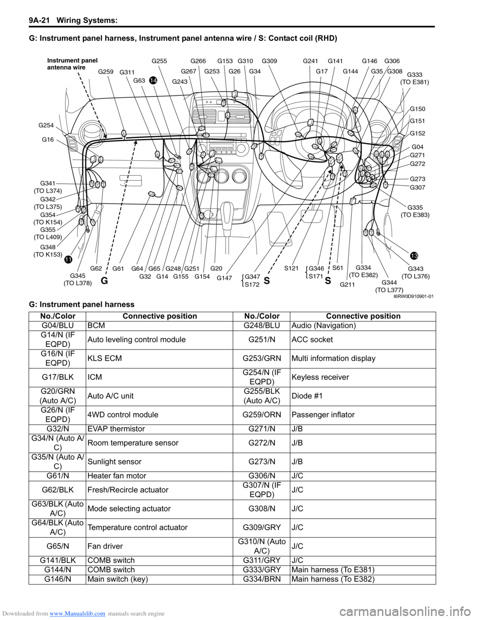
G: Instrument panel harness, Instrument panel antenna wire / S: Contact coil (RHD)
G: Instrument panel harness
G146G141G309
G34G26G253
G266G255
G144
G241
G17
G310G153
G248
G311
G61
G259
1311
14
G16
G341
(TO L374)
G354
(TO K154)
G342
(TO L375)
G348
(TO K153)
G254
G152
G04
G271
G272
G307
G211
G343
(TO L376)
G344
(TO L377) G147G345
(TO L378)
G334
(TO E382)
G333
(TO E381)
G20
S121S61
G32 G155 G154
G63
G62G65G64G273
G151
G150
G308
G306
G35
G251
G347
S172
G346
S171
GSS
Instrument panel
antenna wire
G243
G267
G14
G355
(TO L409)G335
(TO E383)
I6RW0D910901-01
No./Color Connective position No./Color Connective position
G04/BLU BCM G248/BLU Audio (Navigation)
G14/N (IF
EQPD)Auto leveling control module G251/N ACC socket
G16/N (IF
EQPD)KLS ECM G253/GRN Multi information display
G17/BLK ICMG254/N (IF
EQPD)Keyless receiver
G20/GRN
(Auto A/C)Auto A/C unitG255/BLK
(Auto A/C)Diode #1
G26/N (IF
EQPD)4WD control module G259/ORN Passenger inflator
G32/N EVAP thermistor G271/N J/B
G34/N (Auto A/
C)Room temperature sensor G272/N J/B
G35/N (Auto A/
C)Sunlight sensor G273/N J/B
G61/N Heater fan motor G306/N J/C
G62/BLK Fresh/Recircle actuatorG307/N (IF
EQPD)J/C
G63/BLK (Auto
A/C)Mode selecting actuator G308/N J/C
G64/BLK (Auto
A/C)Temperature control actuator G309/GRY J/C
G65/N Fan driverG310/N (Auto
A/C)J/C
G141/BLK COMB switch G311/GRY J/C
G144/N COMB switch G333/GRY Main harness (To E381)
G146/N Main switch (key) G334/BRN Main harness (To E382)