2006 SUZUKI SX4 low oil pressure
[x] Cancel search: low oil pressurePage 1329 of 1556
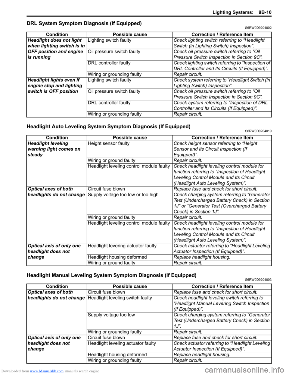
Downloaded from www.Manualslib.com manuals search engine Lighting Systems: 9B-10
DRL System Symptom Diagnosis (If Equipped)S6RW0D9204002
Headlight Auto Leveling System Symptom Diagnosis (If Equipped)S6RW0D9204019
Headlight Manual Leveling System Symptom Diagnosis (If Equipped)S6RW0D9204003
Condition Possible cause Correction / Reference Item
Headlight does not light
when lighting switch is in
OFF position and engine
is runningLighting switch faultyCheck lighting switch referring to “Headlight
Switch (in Lighting Switch) Inspection”.
Oil pressure switch faultyCheck oil pressure switch referring to “Oil
Pressure Switch Inspection in Section 9C”.
DRL controller faultyCheck lighting switch referring to “Inspection of
DRL Controller and Its Circuits (If Equipped)”.
Wiring or grounding faultyRepair circuit.
Headlight lights even if
engine stop and lighting
switch is OFF positionLighting switch faultyCheck system referring to “Headlight Switch (in
Lighting Switch) Inspection”.
Oil pressure switch faultyCheck oil pressure switch referring to “Oil
Pressure Switch Inspection in Section 9C”.
DRL controller faultyCheck system referring to “Inspection of DRL
Controller and Its Circuits (If Equipped)”.
Wiring or grounding faultyRepair circuit.
Condition Possible cause Correction / Reference Item
Headlight leveling
warning light comes on
steadyHeight sensor faultyCheck height sensor referring to “Height
Sensor and Its Circuit Inspection (If
Equipped)”.
Wiring or ground faultyRepair circuit.
Headlight leveling control module faultyCheck headlight leveling control module for
function referring to “Inspection of Headlight
Leveling Control Module and Its Circuit
(Headlight Auto Leveling System)”.
Optical axes of both
headlights do not changeCircuit fuse blownReplace fuse and check for short circuit.
Supply voltage too low or too highCheck charging system referring to “Generator
Test (Undercharged Battery Check) in Section
1J” or “Generator Test (Overcharged Battery
Check) in Section 1J”.
Wiring or ground faultyRepair circuit.
Headlight leveling control module faultyCheck headlight leveling control module for
function referring to “Inspection of Headlight
Leveling Control Module and Its Circuit
(Headlight Auto Leveling System)”.
Optical axis of only one
headlight does not
changeHeadlight levering actuator faultyCheck actuator referring to “Headlight Leveling
Actuator Inspection (If Equipped)”.
Headlight housing deformedReplace headlight housing.
Wiring or ground faultyRepair circuit.
Condition Possible cause Correction / Reference Item
Optical axes of both
headlights do not changeCircuit fuse blownReplace fuse and check for short circuit.
Headlight leveling switch faultyCheck headlight leveling switch referring to
“Headlight Manual Levering Switch Inspection
(If Equipped)”.
Supply voltage too lowCheck charging system referring to “Generator
Test (Undercharged Battery Check) in Section
1J”.
Wiring or grounding faultyRepair circuit.
Optical axis of only one
headlight does not
changeCircuit fuse blownReplace fuse and check for short circuit.
Headlight leveling actuator faultyCheck actuator referring to “Headlight Leveling
Actuator Inspection (If Equipped)”.
Headlight housing deformedReplace headlight housing.
Wiring or grounding faultyRepair circuit.
Page 1332 of 1556
Downloaded from www.Manualslib.com manuals search engine 9B-13 Lighting Systems:
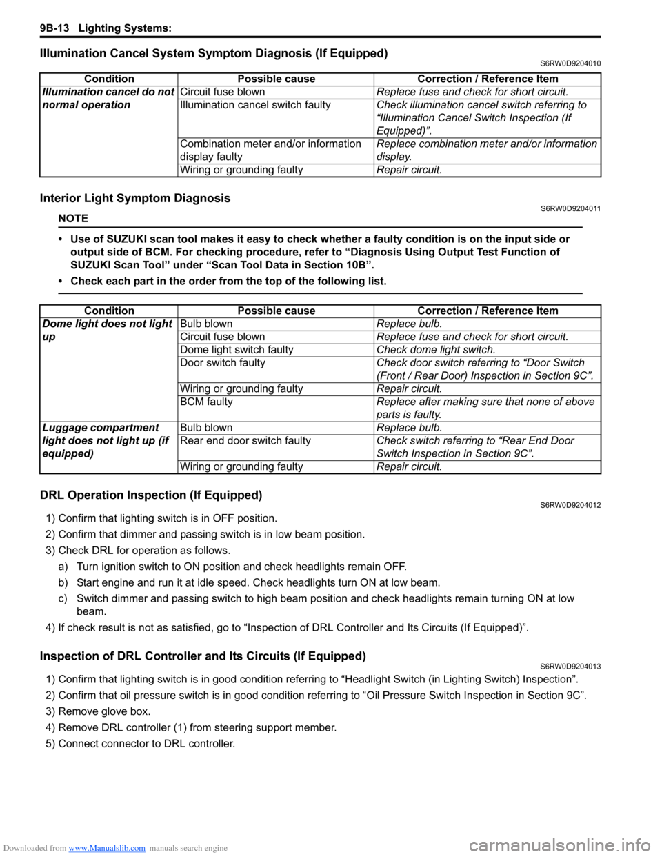
Illumination Cancel System Symptom Diagnosis (If Equipped)S6RW0D9204010
Interior Light Symptom DiagnosisS6RW0D9204011
NOTE
• Use of SUZUKI scan tool makes it easy to check whether a faulty condition is on the input side or
output side of BCM. For checking procedure, refer to “Diagnosis Using Output Test Function of
SUZUKI Scan Tool” under “Scan Tool Data in Section 10B”.
• Check each part in the order from the top of the following list.
DRL Operation Inspection (If Equipped)S6RW0D9204012
1) Confirm that lighting switch is in OFF position.
2) Confirm that dimmer and passing switch is in low beam position.
3) Check DRL for operation as follows.
a) Turn ignition switch to ON position and check headlights remain OFF.
b) Start engine and run it at idle speed. Check headlights turn ON at low beam.
c) Switch dimmer and passing switch to high beam position and check headlights remain turning ON at low
beam.
4) If check result is not as satisfied, go to “Inspection of DRL Controller and Its Circuits (If Equipped)”.
Inspection of DRL Controller and Its Circuits (If Equipped)S6RW0D9204013
1) Confirm that lighting switch is in good condition referring to “Headlight Switch (in Lighting Switch) Inspection”.
2) Confirm that oil pressure switch is in good condition referring to “Oil Pressure Switch Inspection in Section 9C”.
3) Remove glove box.
4) Remove DRL controller (1) from steering support member.
5) Connect connector to DRL controller.Condition Possible cause Correction / Reference Item
Illumination cancel do not
normal operationCircuit fuse blownReplace fuse and check for short circuit.
Illumination cancel switch faultyCheck illumination cancel switch referring to
“Illumination Cancel Switch Inspection (If
Equipped)”.
Combination meter and/or information
display faultyReplace combination meter and/or information
display.
Wiring or grounding faultyRepair circuit.
Condition Possible cause Correction / Reference Item
Dome light does not light
upBulb blownReplace bulb.
Circuit fuse blownReplace fuse and check for short circuit.
Dome light switch faultyCheck dome light switch.
Door switch faultyCheck door switch referring to “Door Switch
(Front / Rear Door) Inspection in Section 9C”.
Wiring or grounding faultyRepair circuit.
BCM faultyReplace after making sure that none of above
parts is faulty.
Luggage compartment
light does not light up (if
equipped)Bulb blownReplace bulb.
Rear end door switch faultyCheck switch referring to “Rear End Door
Switch Inspection in Section 9C”.
Wiring or grounding faultyRepair circuit.
Page 1333 of 1556
Downloaded from www.Manualslib.com manuals search engine Lighting Systems: 9B-14
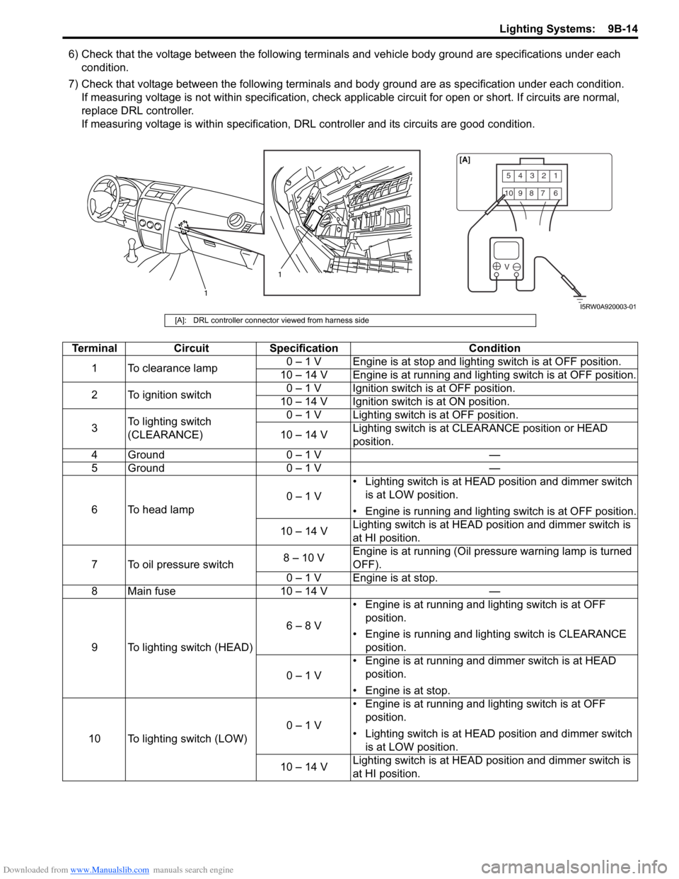
6) Check that the voltage between the following terminals and vehicle body ground are specifications under each
condition.
7) Check that voltage between the following terminals and body ground are as specification under each condition.
If measuring voltage is not within specification, check applicable circuit for open or short. If circuits are normal,
replace DRL controller.
If measuring voltage is within specification, DRL controller and its circuits are good condition.
54321
10987 6
V
1
1[A]
I5RW0A920003-01
[A]: DRL controller connector viewed from harness side
Terminal Circuit Specification Condition
1 To clearance lamp0 – 1 V Engine is at stop and lighting switch is at OFF position.
10 – 14 V Engine is at running and lighting switch is at OFF position.
2 To ignition switch0 – 1 V Ignition switch is at OFF position.
10 – 14 V Ignition switch is at ON position.
3To lighting switch
(CLEARANCE)0 – 1 V Lighting switch is at OFF position.
10 – 14 VLighting switch is at CLEARANCE position or HEAD
position.
4 Ground 0 – 1 V —
5 Ground 0 – 1 V —
6 To head lamp0 – 1 V• Lighting switch is at HEAD position and dimmer switch
is at LOW position.
• Engine is running and lighting switch is at OFF position.
10 – 14 VLighting switch is at HEAD position and dimmer switch is
at HI position.
7 To oil pressure switch8 – 10 VEngine is at running (Oil pressure warning lamp is turned
OFF).
0 – 1 V Engine is at stop.
8 Main fuse 10 – 14 V —
9 To lighting switch (HEAD)6 – 8 V• Engine is at running and lighting switch is at OFF
position.
• Engine is running and lighting switch is CLEARANCE
position.
0 – 1 V• Engine is at running and dimmer switch is at HEAD
position.
• Engine is at stop.
10 To lighting switch (LOW)0 – 1 V• Engine is at running and lighting switch is at OFF
position.
• Lighting switch is at HEAD position and dimmer switch
is at LOW position.
10 – 14 VLighting switch is at HEAD position and dimmer switch is
at HI position.
Page 1359 of 1556
Downloaded from www.Manualslib.com manuals search engine Instrumentation / Driver Info. / Horn: 9C-7
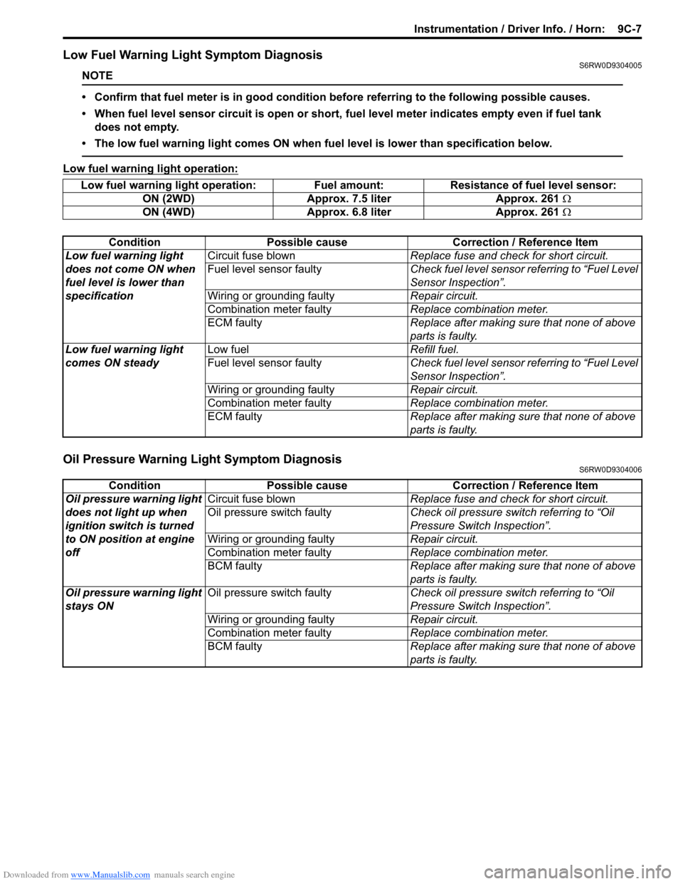
Low Fuel Warning Light Symptom DiagnosisS6RW0D9304005
NOTE
• Confirm that fuel meter is in good condition before referring to the following possible causes.
• When fuel level sensor circuit is open or short, fuel level meter indicates empty even if fuel tank
does not empty.
• The low fuel warning light comes ON when fuel level is lower than specification below.
Low fuel warning light operation:
Oil Pressure Warning Light Symptom DiagnosisS6RW0D9304006
Low fuel warning light operation: Fuel amount: Resistance of fuel level sensor:
ON (2WD) Approx. 7.5 liter Approx. 261 Ω
ON (4WD) Approx. 6.8 liter Approx. 261 Ω
Condition Possible cause Correction / Reference Item
Low fuel warning light
does not come ON when
fuel level is lower than
specificationCircuit fuse blownReplace fuse and check for short circuit.
Fuel level sensor faultyCheck fuel level sensor referring to “Fuel Level
Sensor Inspection”.
Wiring or grounding faultyRepair circuit.
Combination meter faultyReplace combination meter.
ECM faultyReplace after making sure that none of above
parts is faulty.
Low fuel warning light
comes ON steadyLow fuelRefill fuel.
Fuel level sensor faultyCheck fuel level sensor referring to “Fuel Level
Sensor Inspection”.
Wiring or grounding faultyRepair circuit.
Combination meter faultyReplace combination meter.
ECM faultyReplace after making sure that none of above
parts is faulty.
Condition Possible cause Correction / Reference Item
Oil pressure warning light
does not light up when
ignition switch is turned
to ON position at engine
offCircuit fuse blownReplace fuse and check for short circuit.
Oil pressure switch faultyCheck oil pressure switch referring to “Oil
Pressure Switch Inspection”.
Wiring or grounding faultyRepair circuit.
Combination meter faultyReplace combination meter.
BCM faultyReplace after making sure that none of above
parts is faulty.
Oil pressure warning light
stays ONOil pressure switch faultyCheck oil pressure switch referring to “Oil
Pressure Switch Inspection”.
Wiring or grounding faultyRepair circuit.
Combination meter faultyReplace combination meter.
BCM faultyReplace after making sure that none of above
parts is faulty.
Page 1367 of 1556
Downloaded from www.Manualslib.com manuals search engine Instrumentation / Driver Info. / Horn: 9C-15
3) Remove center ventilation louver referring to Step 1)
and 2) of “Information Display (Clock) Removal and
Installation”.
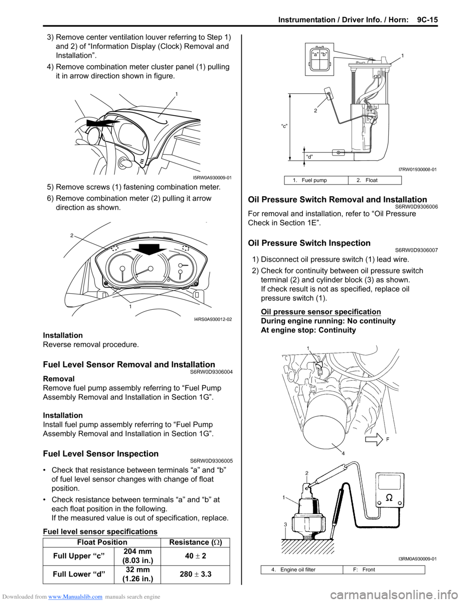
4) Remove combination meter cluster panel (1) pulling
it in arrow direction shown in figure.
5) Remove screws (1) fastening combination meter.
6) Remove combination meter (2) pulling it arrow
direction as shown.
Installation
Reverse removal procedure.
Fuel Level Sensor Removal and InstallationS6RW0D9306004
Removal
Remove fuel pump assembly referring to “Fuel Pump
Assembly Removal and Installation in Section 1G”.
Installation
Install fuel pump assembly referring to “Fuel Pump
Assembly Removal and Installation in Section 1G”.
Fuel Level Sensor InspectionS6RW0D9306005
• Check that resistance between terminals “a” and “b”
of fuel level sensor changes with change of float
position.
• Check resistance between terminals “a” and “b” at
each float position in the following.
If the measured value is out of specification, replace.
Fuel level sensor specifications
Oil Pressure Switch Removal and InstallationS6RW0D9306006
For removal and installation, refer to “Oil Pressure
Check in Section 1E”.
Oil Pressure Switch InspectionS6RW0D9306007
1) Disconnect oil pressure switch (1) lead wire.
2) Check for continuity between oil pressure switch
terminal (2) and cylinder block (3) as shown.
If check result is not as specified, replace oil
pressure switch (1).
Oil pressure sensor specification
During engine running: No continuity
At engine stop: Continuity
Float Position Resistance (Ω)
Full Upper “c”204 mm
(8.03 in.)40 ± 2
Full Lower “d”32 mm
(1.26 in.)280 ± 3.3
1
I5RW0A930009-01
1
2
I4RS0A930012-02
1. Fuel pump 2. Float
4. Engine oil filter F: Front
“c”
“d”
“b” “a”1
2
I7RW01930008-01
I3RM0A930009-01
Page 1404 of 1556
Downloaded from www.Manualslib.com manuals search engine 9E-19 Glass / Windows / Mirrors:
Rear End Door Window Defogger Relay
Inspection
S6RW0D9506018
1) Disconnect negative (–) cable from battery.
2) Remove junction block for inspection of rear end
door window defogger relay.
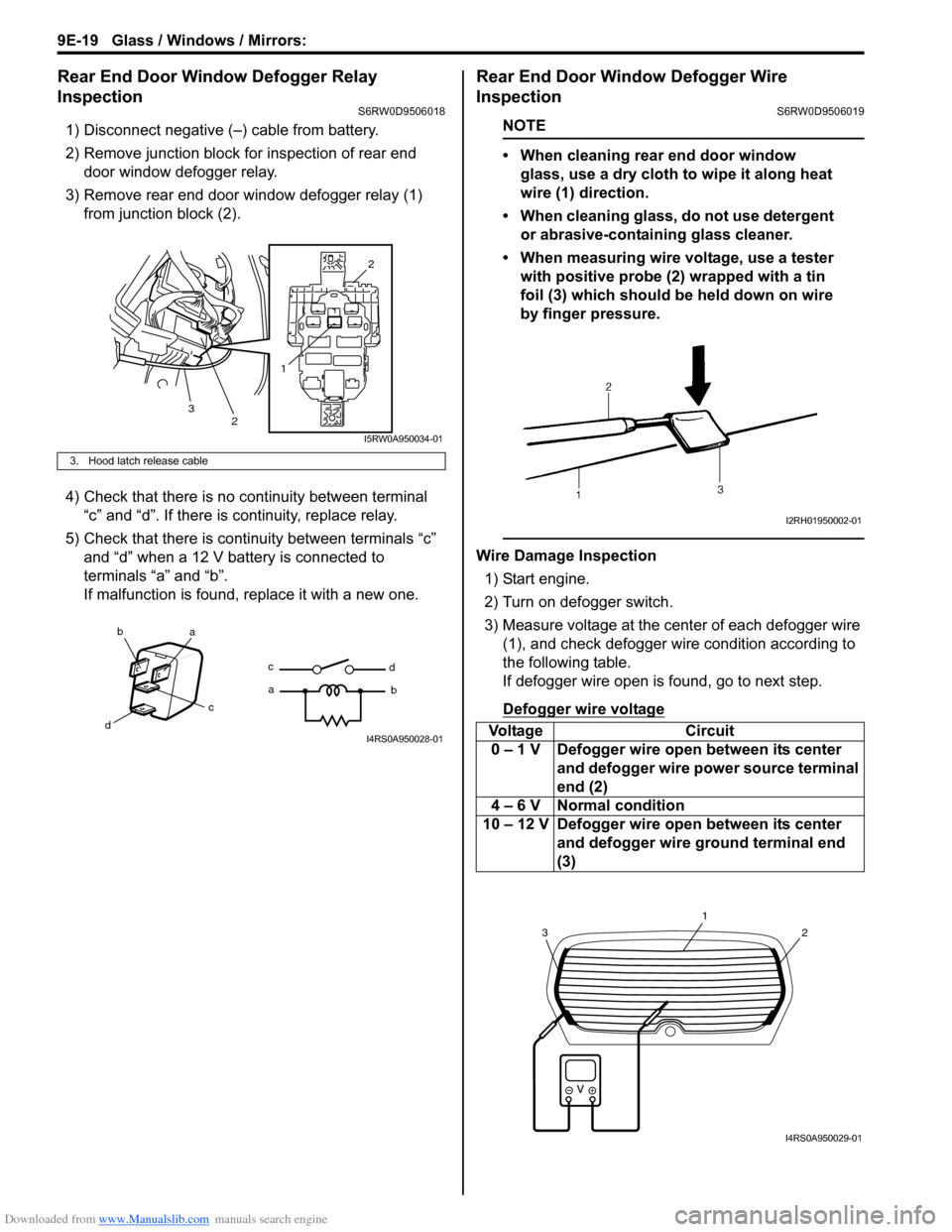
3) Remove rear end door window defogger relay (1)
from junction block (2).
4) Check that there is no continuity between terminal
“c” and “d”. If there is continuity, replace relay.
5) Check that there is continuity between terminals “c”
and “d” when a 12 V battery is connected to
terminals “a” and “b”.
If malfunction is found, replace it with a new one.
Rear End Door Window Defogger Wire
Inspection
S6RW0D9506019
NOTE
• When cleaning rear end door window
glass, use a dry cloth to wipe it along heat
wire (1) direction.
• When cleaning glass, do not use detergent
or abrasive-containing glass cleaner.
• When measuring wire voltage, use a tester
with positive probe (2) wrapped with a tin
foil (3) which should be held down on wire
by finger pressure.
Wire Damage Inspection
1) Start engine.
2) Turn on defogger switch.
3) Measure voltage at the center of each defogger wire
(1), and check defogger wire condition according to
the following table.
If defogger wire open is found, go to next step.
Defogger wire voltage
3. Hood latch release cable
12
2
3
I5RW0A950034-01
ba
c
dc
ad
bI4RS0A950028-01Voltage Circuit
0 – 1 V Defogger wire open between its center
and defogger wire power source terminal
end (2)
4 – 6 V Normal condition
10 – 12 V Defogger wire open between its center
and defogger wire ground terminal end
(3)
I2RH01950002-01
2
1
3
I4RS0A950029-01
Page 1474 of 1556
Downloaded from www.Manualslib.com manuals search engine 10B-1 Body Electrical Control System:
Control Systems
Body Electrical Control System
Precautions
Precautions in Diagnosing TroubleS6RW0DA200001
• Diagnostic information stored in BCM memory can be cleared as well as checked by using SUZUKI scan tool.
Before using scan tool, read its Operator’s (Instruction) Manual carefully to have good understanding as to what
functions are available and how to use it.
• Be sure to read “Precautions for Electrical Circuit Service in Section 00” before inspection and observe what is
written there.
• Communication of ECM, TCM (A/T model), ABS control module, 4WD control module (if equipped), keyless start
control module (if equipped), combination meter and BCM is established by CAN (Controller Area Network). For
detail of CAN communication for BCM, refer to “CAN Communication System Description”. Therefore, handle CAN
communication line with care referring to “Precaution for CAN Communication System in Section 00”.
General Description
BCM General DescriptionS6RW0DA201001
The Body electrical Control Module (BCM) is
incorporated in junction block. Do not attempt removal of
BCM from junction block as it may cause contact failure.
The BCM incorporates relays and controllers which are
used for the following systems and controls them.
• Power door lock (if equipped)
• Keyless entry (if equipped)
• Door lock function of keyless start system (if
equipped)
• Rear wiper
• Combination meter
• Interior light• Warning buzzer
• Rear end door window defogger and door mirror
heater (if equipped)
• Rear end door opener (if equipped)
• Theft deterrent light
Also, the BCM has a function to cause the interior light
and open door warning light in the combination meter to
turn off when any door is left open for longer than 15
minutes to reduce wasteful battery consumption.
In addition, it is possible to check operation of actuator
which is controlled by BCM by using the output test
function of SUZUKI scan tool to operate actuator
simulatively.
CAN Communication System DescriptionS6RW0DA201002
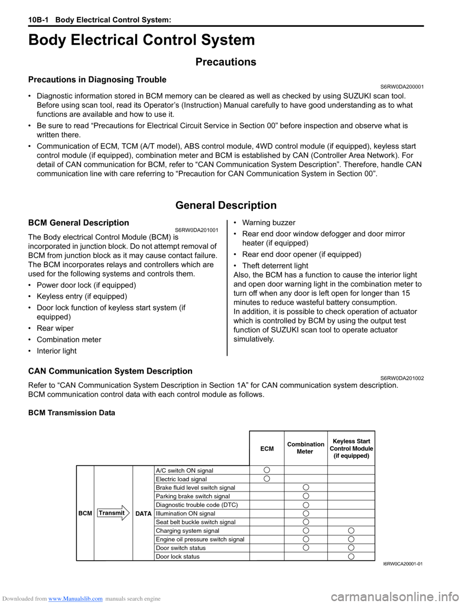
Refer to “CAN Communication System Description in Section 1A” for CAN communication system description.
BCM communication control data with each control module as follows.
BCM Transmission Data
A/C switch ON signal
Electric load signal
Brake fluid level switch signal
Parking brake switch signal
Diagnostic trouble code (DTC)
Illumination ON signal
Seat belt buckle switch signal
Charging system signal
Engine oil pressure switch signal
Door switch status
Door lock statusECMKeyless Start
Control Module
(if equipped) Combination
Meter
BCMTransmit
DATA
I6RW0CA20001-01
Page 1481 of 1556
Downloaded from www.Manualslib.com manuals search engine Body Electrical Control System: 10B-8
Diagnostic Information and Procedures
BCM Self-Diagnosis FunctionS6RW0DA204001
• BCM monitors conditions of the system components and its circuit with ignition switch turned to ON position. When
an abnormality in the system occurs, the area where that abnormality lies is stored in the memory of EEPROM in
BCM.
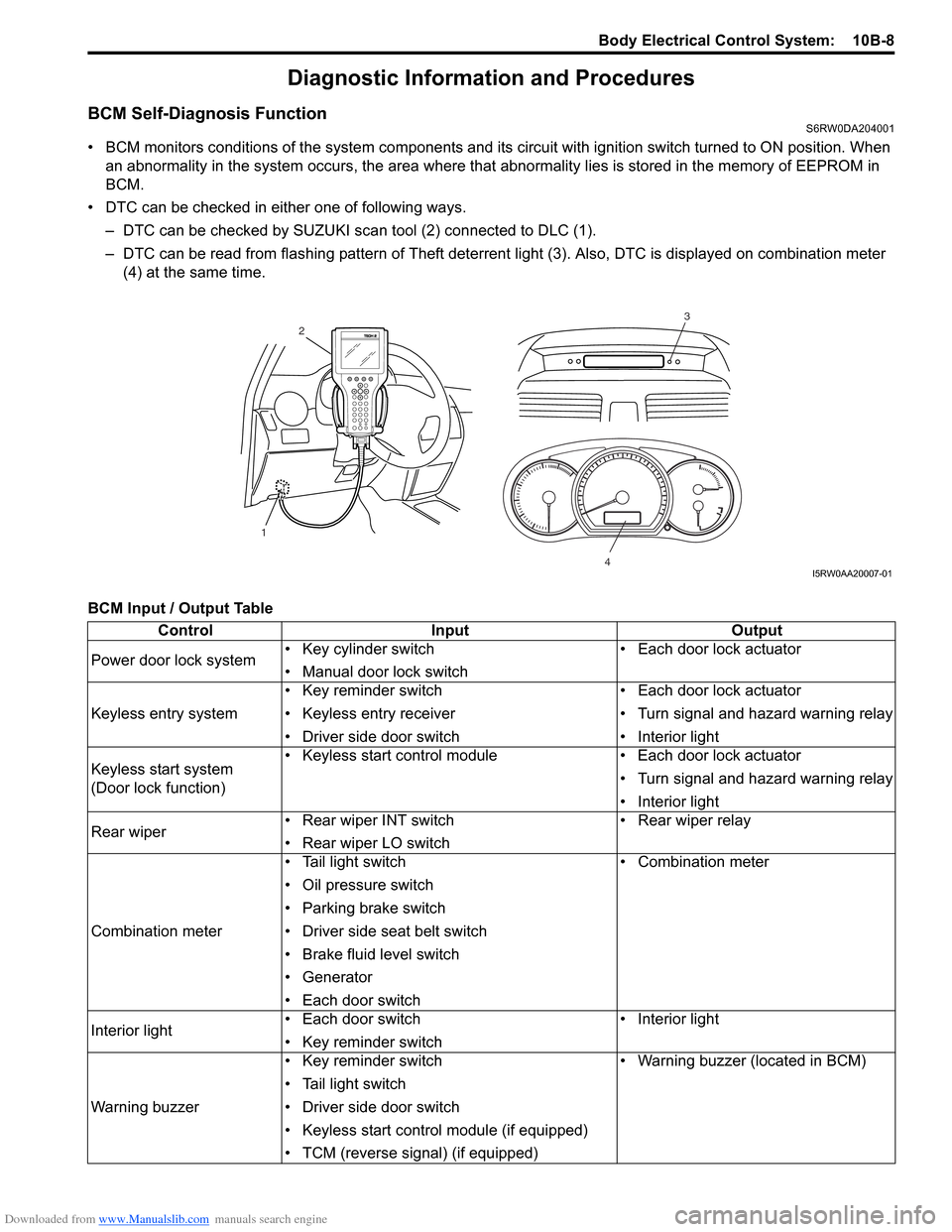
• DTC can be checked in either one of following ways.
– DTC can be checked by SUZUKI scan tool (2) connected to DLC (1).
– DTC can be read from flashing pattern of Theft deterrent light (3). Also, DTC is displayed on combination meter
(4) at the same time.
BCM Input / Output Table
3
4
2
1
I5RW0AA20007-01
Control Input Output
Power door lock system• Key cylinder switch
• Manual door lock switch• Each door lock actuator
Keyless entry system• Key reminder switch
• Keyless entry receiver
• Driver side door switch• Each door lock actuator
• Turn signal and hazard warning relay
• Interior light
Keyless start system
(Door lock function)• Keyless start control module • Each door lock actuator
• Turn signal and hazard warning relay
• Interior light
Rear wiper • Rear wiper INT switch
• Rear wiper LO switch• Rear wiper relay
Combination meter• Tail light switch
• Oil pressure switch
• Parking brake switch
• Driver side seat belt switch
• Brake fluid level switch
• Generator
• Each door switch• Combination meter
Interior light• Each door switch
• Key reminder switch• Interior light
Warning buzzer• Key reminder switch
• Tail light switch
• Driver side door switch
• Keyless start control module (if equipped)
• TCM (reverse signal) (if equipped)• Warning buzzer (located in BCM)