2006 SUZUKI SX4 low oil pressure
[x] Cancel search: low oil pressurePage 869 of 1556

Downloaded from www.Manualslib.com manuals search engine Steering General Diagnosis: 6A-2
Steering System InspectionS6RW0D6104002
Check steering system referring to the following items.Erratic steering when
brakingWorn wheel bearingsReplace wheel bearing.
Broken or sagging coil springsReplace coil spring.
Wheel tires are inflated unequallyInflate tires to proper pressure.
Disturbed front wheel alignmentCheck and adjust front wheel alignment.
Brakes not working in unisonCheck and repair brake system.
Leaking wheel cylinder or caliperRepair or replace wheel cylinder or caliper.
Warped discsReplace brake disc.
Badly worn brake liningsReplace brake shoe lining.
Drum is out of round in some brakesReplace brake drum.
Defective wheel cylindersReplace or repair wheel cylinder. Condition Possible cause Correction / Reference Item
Inspection Item Referring section
Steering wheel Play, rattle “Steering Wheel Play Check in Section 6C”
Tie-rod end Looseness and damage “Tie-Rod End Inspection in Section 6C”
Wheel alignment “Front Wheel Alignment Inspection and Adjustment in
Section 2B”
Tie-rod end boot Damage “Tie-Rod End Boot On-Vehicle Inspection in Section 6C”
Steering rack boot Damage “Steering Rack Boot Inspection in Section 6C”
Steering shaft joint Rattle and damage “Steering Shaft Joint On-Vehicle Inspection in Section 6C”
EPS system Operation “EPS System Check in Section 6C”
Page 949 of 1556

Downloaded from www.Manualslib.com manuals search engine Air Conditioning System: Manual Type 7B-9
10) Check for each pressure of low side and high side if it is within shaded range of graph. If each gauge reading is out
of specified pressure, correct defective part referring to the following table.
When diagnosing troubles of abnormal pressure on the low side and high side for each pressure more specifically,
refer to “Trouble Diagnosis for Abnormal Pressure”.
NOTE
Pressure registered on gauge varies with ambient temperature. Therefore, use the graphs when
determining if pressures are normal or not.
Low side and high side pressure example, Gauges should read as follows when ambient temperature is 30
°C (86 °F)
Pressure on high pressure gauge (HI): 1130 – 1560 kPa (11.4 – 15.6 kgf/cm2)
Pressure on low pressure gauge (LO): 270 – 390 kPa (2.7 – 3.9 kgf/cm2)
High pressure gauge
[A]: Pressure of high pressure gauge [C]: Ambient temperature [E]: Acceptable range
[B]: Pressure of low pressure gauge [D]: Humidity
Condition Possible cause Correction
Pressure is higher than
acceptable range
(“A” area)Refrigerant overcharged Recharge.
Expansion valve frozen or clogged Check expansion valve.
Clogged refrigerant passage of high pressure side Clean or replace.
Condenser cooling fan malfunction (Insufficient
cooling of condenser)Check condenser cooling fan.
Dirty or bent condenser fins (Insufficient cooling of
condenser)Clean or repair.
Compressor malfunction (Insufficient oil etc.) Check compressor.
Engine overheat Check engine cooling system
referring to “Engine Cooling Symptom
Diagnosis in Section 1F”.
22 312.9 2200
0 1 2 3
30 70 30 70%
4 5 6 7 8 9 10
11 12 13
14
15
16
17
18
19 21 298.7 2100
20
14.2 28.4 42.7 56.9 71.1 85.3 99.5 113.8 128.0
142.2
151.4 170.6 184.9
199.1
213.3
227.5
241.7
256.0
270.2
284.4
100 200 300 400 500 600 700 800 900 1000
1100 1200 1300
1400
1500
1600
1700
1800
1900
2000
25 30 35
77 86 95 psi kPa kgf/cm
2
[C] [B] [A]
C
F
“A”
“B”
“C”
[E]
[E]
“D”[D]
I6RW0D721001-01
Page 952 of 1556

Downloaded from www.Manualslib.com manuals search engine 7B-12 Air Conditioning System: Manual Type
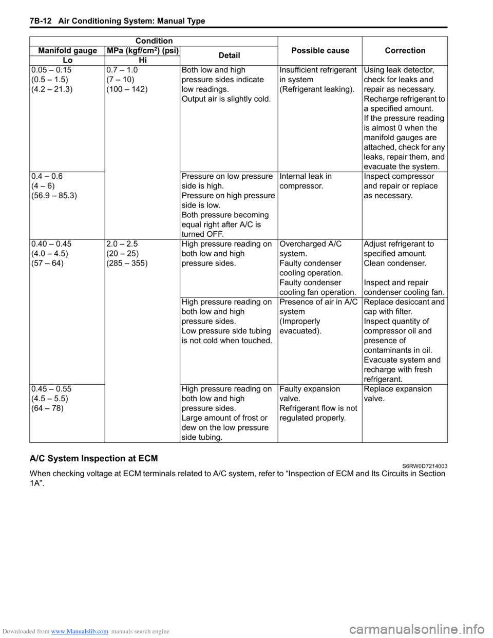
A/C System Inspection at ECMS6RW0D7214003
When checking voltage at ECM terminals related to A/C system, refer to “Inspection of ECM and Its Circuits in Section
1A”.0.05 – 0.15
(0.5 – 1.5)
(4.2 – 21.3)0.7 – 1.0
(7 – 10)
(100 – 142)Both low and high
pressure sides indicate
low readings.
Output air is slightly cold.Insufficient refrigerant
in system
(Refrigerant leaking).Using leak detector,
check for leaks and
repair as necessary.
Recharge refrigerant to
a specified amount.
If the pressure reading
is almost 0 when the
manifold gauges are
attached, check for any
leaks, repair them, and
evacuate the system.
0.4 – 0.6
(4 – 6)
(56.9 – 85.3)Pressure on low pressure
side is high.
Pressure on high pressure
side is low.
Both pressure becoming
equal right after A/C is
turned OFF.Internal leak in
compressor.Inspect compressor
and repair or replace
as necessary.
0.40 – 0.45
(4.0 – 4.5)
(57 – 64)2.0 – 2.5
(20 – 25)
(285 – 355)High pressure reading on
both low and high
pressure sides.Overcharged A/C
system.Adjust refrigerant to
specified amount.
Faulty condenser
cooling operation.Clean condenser.
Faulty condenser
cooling fan operation.Inspect and repair
condenser cooling fan.
High pressure reading on
both low and high
pressure sides.
Low pressure side tubing
is not cold when touched.Presence of air in A/C
system
(Improperly
evacuated).Replace desiccant and
cap with filter.
Inspect quantity of
compressor oil and
presence of
contaminants in oil.
Evacuate system and
recharge with fresh
refrigerant.
0.45 – 0.55
(4.5 – 5.5)
(64 – 78)High pressure reading on
both low and high
pressure sides.
Large amount of frost or
dew on the low pressure
side tubing.Faulty expansion
valve.
Refrigerant flow is not
regulated properly.Replace expansion
valve. Condition
Possible cause Correction Manifold gauge MPa (kgf/cm
2) (psi)
Detail
Lo Hi
Page 969 of 1556

Downloaded from www.Manualslib.com manuals search engine Air Conditioning System: Manual Type 7B-29
A/C Refrigerant Pressure Sensor and Its Circuit
Inspection
S6RW0D7216014
1) Disconnect A/C refrigerant pressure sensor
connector.
2) Turn ignition switch to ON position.
3) Check if voltage between “RED” wire terminal and
“ORN” wire terminal of A/C refrigerant pressure
sensor connector is 4.75 V to 5.25 V.
If not, check A/C refrigerant pressure sensor circuit.
4) Connect A/C refrigerant pressure sensor connector
with ignition switch turned OFF.
5) Connect manifold gauge set to the charging valves.
6) Check A/C refrigerant pressure sensor voltage of
ECM connector referring to “A/C System Inspection
at ECM”.
If voltage is not as specified below, replace A/C
refrigerant pressure sensor.
A/C refrigerant pressure sensor voltage
specifications (A/C refrigerant pressure measured
by manifold gauge)
0.8 MPa (8.0 kgf/cm2, 116 psi): 1.40 – 1.78 V
1.4 MPa (14 kgf/cm2, 203 psi): 2.18 – 2.64 V
1.6 MPa (16 kgf/cm2, 232 psi): 2.44 – 2.92 V
1.8 MPa (18 kgf/cm2, 261 psi): 2.70 – 3.21 V
A/C Refrigerant Pressure Sensor Removal and
Installation
S6RW0D7216015
Removal
1) Recover refrigerant from the A/C system with the
recovery and recycling equipment referring to
“Recovery” in “Operation Procedure for Refrigerant
Charge”.
2) Disconnect negative (–) cable from battery.
3) Disconnect A/C refrigerant pressure sensor
connector.
4) Remove A/C refrigerant pressure sensor (1) from
liquid pipe (2).Installation
Reverse removal procedure noting the following
instructions.
• Apply compressor oil to O-ring of A/C refrigerant
pressure sensor.
• Tighten A/C refrigerant pressure sensor to specified
torque.
Tightening torque
A/C refrigerant pressure sensor (a): 11 N·m (1.1
kgf-m, 8.0 lb-ft)
• Evacuate and charge the A/C system referring to
“Evacuation” and “Charge” in “Operation Procedure
for Refrigerant Charge”.
A/C Switch InspectionS6RW0D7216016
• Check that there is continuity between terminal (1)
and terminal (2) when A/C switch is at ON position.
• Check that there is no continuity between terminal (1)
and terminal (2) when A/C switch is at OFF position.
If check result does not meet the above conditions,
replace HVAC control unit.
2
1
I5RW0A721029-01
(a)
I5RW0A721030-01
1
2
I5RW0A721031-01
Page 977 of 1556

Downloaded from www.Manualslib.com manuals search engine Air Conditioning System: Manual Type 7B-37
Specifications
Tightening Torque SpecificationsS6RW0D7217001
NOTE
The specified tightening torque is also described in the following.
“A/C System Major Components Location”
“Compressor Assembly Components”
Reference:
For the tightening torque of fastener not specified in this section, refer to “Fasteners Information in Section 0A”.
Special Tools and Equipment
Recommended Service MaterialS6RW0D7218001
NOTE
Required service material is also described in the following.
“HVAC Unit Components”
“Compressor Assembly Components”
Special ToolS6RW0D7218002
Fastening partTightening torque
Note
N⋅mkgf-mlb-ft
Expansion valve bolt 4.5 0.45 3.5�)
A/C refrigerant pressure sensor 11 1.1 8.0�)
Compressor mounting bolt 25 2.5 18.0�)
Armature plate nut 16 1.6 11.5�)
Relief valve 8 0.8 6.0�)
Material SUZUKI recommended product or Specification Note
Compressor oil MATSUSHITADENKI GU10 P/No.: 99000–99015–
00A�)
Silicon sealant SUZUKI SILICON SEALANT KE-
347W (100g)P/No.: 99000–34220�)
09900–06107 09990–06020
Snap ring pliers (opening
type)Manifold gauge set (R134a)
�) / �) / �) / �) / �)1.Manifold gauge
2.Charging hoses 3.Quick
connector 4.Refrigerant
container tap valve
5.Refrigerant container T
joint 6.Packing sets 7.Case
�)
09990–86012 09991–06310
Gas leak detector Armature plate holder
This kit includes following
items.1. Gas leak detector,
2. Instruction manual, 3.
Filter, 4. Sensor, 5. Dri-sell
battery (size D) �) / �)�) / �)
12
34
5
Page 1163 of 1556

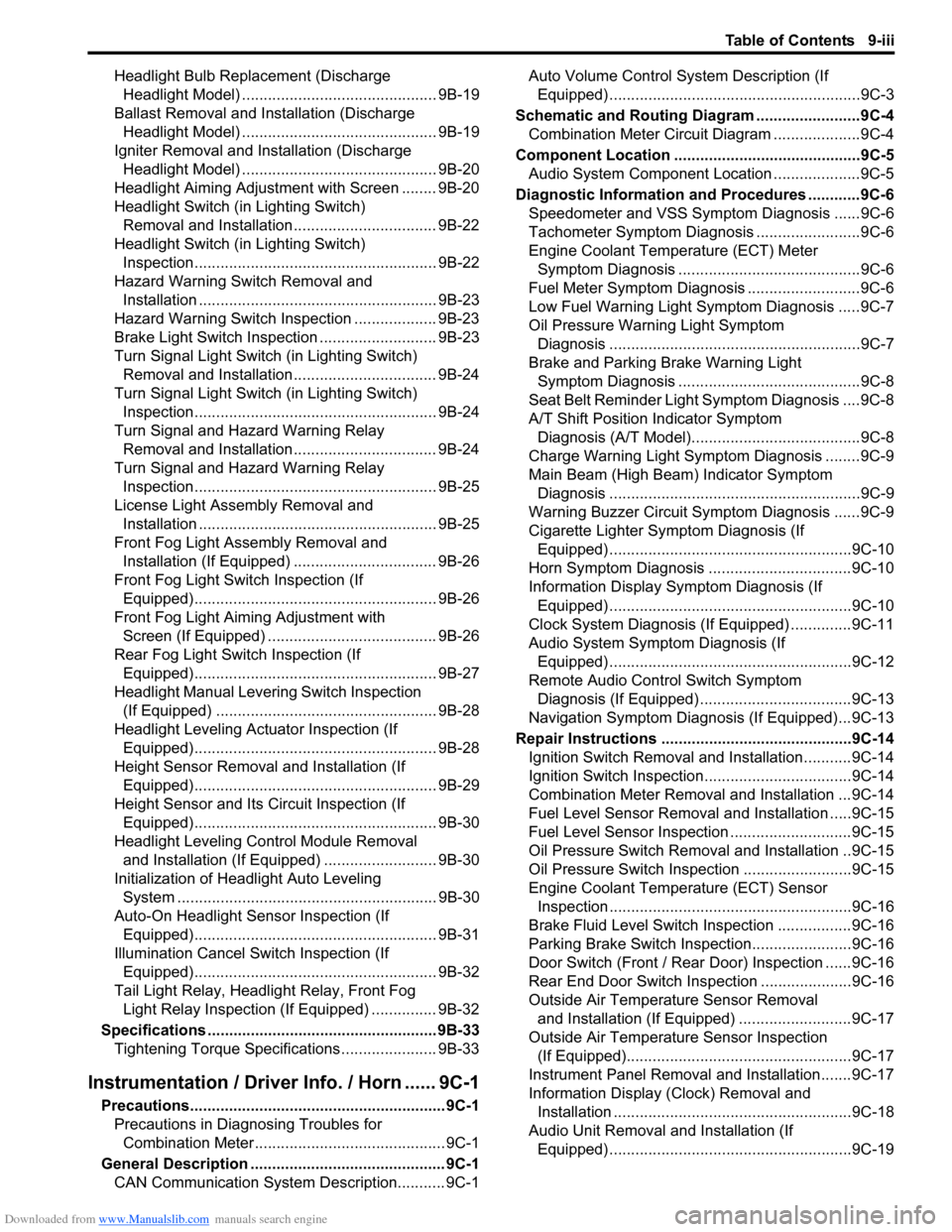
Downloaded from www.Manualslib.com manuals search engine Table of Contents 9-iii
Headlight Bulb Replacement (Discharge
Headlight Model) ............................................. 9B-19
Ballast Removal and Installation (Discharge
Headlight Model) ............................................. 9B-19
Igniter Removal and Installation (Discharge
Headlight Model) ............................................. 9B-20
Headlight Aiming Adjustment with Screen ........ 9B-20
Headlight Switch (in Lighting Switch)
Removal and Installation................................. 9B-22
Headlight Switch (in Lighting Switch)
Inspection........................................................ 9B-22
Hazard Warning Switch Removal and
Installation ....................................................... 9B-23
Hazard Warning Switch Inspection ................... 9B-23
Brake Light Switch Inspection ........................... 9B-23
Turn Signal Light Switch (in Lighting Switch)
Removal and Installation................................. 9B-24
Turn Signal Light Switch (in Lighting Switch)
Inspection........................................................ 9B-24
Turn Signal and Hazard Warning Relay
Removal and Installation................................. 9B-24
Turn Signal and Hazard Warning Relay
Inspection........................................................ 9B-25
License Light Assembly Removal and
Installation ....................................................... 9B-25
Front Fog Light Assembly Removal and
Installation (If Equipped) ................................. 9B-26
Front Fog Light Switch Inspection (If
Equipped)........................................................ 9B-26
Front Fog Light Aiming Adjustment with
Screen (If Equipped) ....................................... 9B-26
Rear Fog Light Switch Inspection (If
Equipped)........................................................ 9B-27
Headlight Manual Levering Switch Inspection
(If Equipped) ................................................... 9B-28
Headlight Leveling Actuator Inspection (If
Equipped)........................................................ 9B-28
Height Sensor Removal and Installation (If
Equipped)........................................................ 9B-29
Height Sensor and Its Circuit Inspection (If
Equipped)........................................................ 9B-30
Headlight Leveling Control Module Removal
and Installation (If Equipped) .......................... 9B-30
Initialization of Headlight Auto Leveling
System ............................................................ 9B-30
Auto-On Headlight Sensor Inspection (If
Equipped)........................................................ 9B-31
Illumination Cancel Switch Inspection (If
Equipped)........................................................ 9B-32
Tail Light Relay, Headlight Relay, Front Fog
Light Relay Inspection (If Equipped) ............... 9B-32
Specifications..................................................... 9B-33
Tightening Torque Specifications ...................... 9B-33
Instrumentation / Driver Info. / Horn ...... 9C-1
Precautions........................................................... 9C-1
Precautions in Diagnosing Troubles for
Combination Meter............................................ 9C-1
General Description ............................................. 9C-1
CAN Communication System Description........... 9C-1Auto Volume Control System Description (If
Equipped) ..........................................................9C-3
Schematic and Routing Diagram ........................9C-4
Combination Meter Circuit Diagram ....................9C-4
Component Location ...........................................9C-5
Audio System Component Location ....................9C-5
Diagnostic Information and Procedures ............9C-6
Speedometer and VSS Symptom Diagnosis ......9C-6
Tachometer Symptom Diagnosis ........................9C-6
Engine Coolant Temperature (ECT) Meter
Symptom Diagnosis ..........................................9C-6
Fuel Meter Symptom Diagnosis ..........................9C-6
Low Fuel Warning Light Symptom Diagnosis .....9C-7
Oil Pressure Warning Light Symptom
Diagnosis ..........................................................9C-7
Brake and Parking Brake Warning Light
Symptom Diagnosis ..........................................9C-8
Seat Belt Reminder Light Symptom Diagnosis ....9C-8
A/T Shift Position Indicator Symptom
Diagnosis (A/T Model).......................................9C-8
Charge Warning Light Symptom Diagnosis ........9C-9
Main Beam (High Beam) Indicator Symptom
Diagnosis ..........................................................9C-9
Warning Buzzer Circuit Symptom Diagnosis ......9C-9
Cigarette Lighter Symptom Diagnosis (If
Equipped) ........................................................9C-10
Horn Symptom Diagnosis .................................9C-10
Information Display Symptom Diagnosis (If
Equipped) ........................................................9C-10
Clock System Diagnosis (If Equipped) ..............9C-11
Audio System Symptom Diagnosis (If
Equipped) ........................................................9C-12
Remote Audio Control Switch Symptom
Diagnosis (If Equipped) ...................................9C-13
Navigation Symptom Diagnosis (If Equipped)...9C-13
Repair Instructions ............................................9C-14
Ignition Switch Removal and Installation...........9C-14
Ignition Switch Inspection..................................9C-14
Combination Meter Removal and Installation ...9C-14
Fuel Level Sensor Removal and Installation .....9C-15
Fuel Level Sensor Inspection ............................9C-15
Oil Pressure Switch Removal and Installation ..9C-15
Oil Pressure Switch Inspection .........................9C-15
Engine Coolant Temperature (ECT) Sensor
Inspection ........................................................9C-16
Brake Fluid Level Switch Inspection .................9C-16
Parking Brake Switch Inspection.......................9C-16
Door Switch (Front / Rear Door) Inspection ......9C-16
Rear End Door Switch Inspection .....................9C-16
Outside Air Temperature Sensor Removal
and Installation (If Equipped) ..........................9C-17
Outside Air Temperature Sensor Inspection
(If Equipped)....................................................9C-17
Instrument Panel Removal and Installation.......9C-17
Information Display (Clock) Removal and
Installation .......................................................9C-18
Audio Unit Removal and Installation (If
Equipped) ........................................................9C-19
Page 1168 of 1556

Downloaded from www.Manualslib.com manuals search engine 9A-1 Wiring Systems:
Body, Cab and Accessories
Wiring Systems
Precautions
Cautions in Body Electrical System ServicingS6RW0D9100001
When servicing the electric systems, observe the cautions described in “Air Bag Warning in Section 00” to protect
electrical parts and to prevent a fire.
General Description
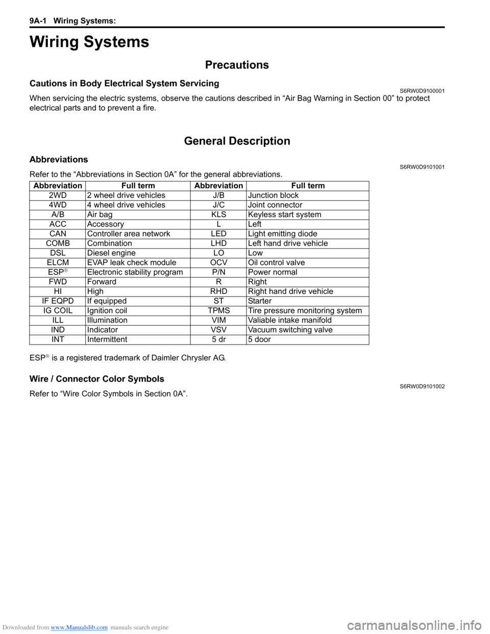
AbbreviationsS6RW0D9101001
Refer to the “Abbreviations in Section 0A” for the general abbreviations.
ESP
® is a registered trademark of Daimler Chrysler AG.
Wire / Connector Color SymbolsS6RW0D9101002
Refer to “Wire Color Symbols in Section 0A”. Abbreviation Full term Abbreviation Full term
2WD 2 wheel drive vehicles J/B Junction block
4WD 4 wheel drive vehicles J/C Joint connector
A/B Air bag KLS Keyless start system
ACC Accessory L Left
CAN Controller area network LED Light emitting diode
COMB Combination LHD Left hand drive vehicle
DSL Diesel engine LO Low
ELCM EVAP leak check module OCV Oil control valve
ESP
®Electronic stability program P/N Power normal
FWD Forward R Right
HI High RHD Right hand drive vehicle
IF EQPD If equipped ST Starter
IG COIL Ignition coil TPMS Tire pressure monitoring system
ILL Illumination VIM Valiable intake manifold
IND Indicator VSV Vacuum switching valve
INT Intermittent 5 dr 5 door
Page 1273 of 1556

Downloaded from www.Manualslib.com manuals search engine Wiring Systems: 9A-106
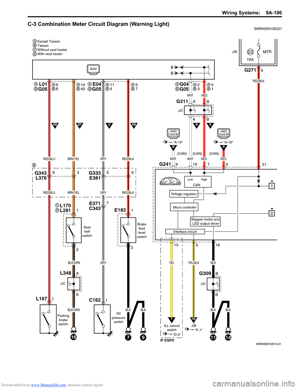
C-3 Combination Meter Circuit Diagram (Warning Light)S6RW0D910E021
J/BMTR
10A22
31
Stepper motor and
LED output driver
Voltage regulator
Micro controller
G2716
RED/BLK
516
YB
YEL/BLK
"F-1"
CAN
High Low
WHTWHTRED
RW
10G2419
7
L01
G05
RED/BLUBRN/YEL
L1671
Parking
brake
switch
1
2
A
A
16
BLK/ORN
BLK/ORN
J/C
L348B
B
J/C
G309
Seat
belt
switch
Oil
pressure
switch
J/B
13
Y
YEL
"D-4"
ILL cancel
switch
E371
C3437
G343
L37693G333
E38156
GRY
GRY
1C162
RED/BLK
RED/BLUBRN/YELGRYRED/BLK
E1831
Brake
fluid
level
switch
2
71114
BLK
BLK
BLK
9
BLKBLK
W
WHTRED
1
2
A
AB
B
J/C
G311
RBGBYRB
BCM
"A-10"
4WD
Cont.M
Interface circuit
RED
6
R"A-10"
4WD
Cont.M
(CAN) (CAN) (CAN)
IF EQPD
Except Taiwan
Taiwan
Without seat heater
With seat heater A
A
B
L170
L281C
D
G04
G05A
BE04
G05A
B
BCD
B
6
8AB14
40AB11
9AB5
7AB2
3AB4
1AB
I6RW0D910915-01