Page 944 of 1556
Downloaded from www.Manualslib.com manuals search engine 7B-4 Air Conditioning System: Manual Type
Schematic and Routing Diagram
A/C System Air Flow DiagramS6RW0D7212001
1312
13 9
9 10
11 11 1514
1718
: A
: B
4
7
356
2 16
8
191
20
I7RW01721002-03
A: Air flow 5. Discharge hose 11. Foot air 17. Air intake door
B: Refrigerant flow 6. Suction hose 12. Front defroster air 18. Temperature control door
1. HVAC unit 7. Liquid pipe 13. Side defroster air 19. Air flow control door
2. Compressor 8. Expansion valve 14. Fresh air 20. Heater core
3. Condenser assembly 9. Side ventilation air 15. Recirculation air
4. Receiver/dryer 10. Center ventilation air 16. Evaporator
Page 948 of 1556

Downloaded from www.Manualslib.com manuals search engine 7B-8 Air Conditioning System: Manual Type
Diagnostic Information and Procedures
A/C System Performance InspectionS6RW0D7214001
1) Confirm that vehicle and environmental conditions
are as follows.
• Vehicle is put indoors.
• Ambient temperature is within 25 – 35 °C (77 – 95
°F).
• Relative humidity is within 30 – 70%.
• There is no wind indoors.
• HVAC unit is normal.
• Blower motor is normal.
• There is no air leakage from air ducts.
• Condenser fins are clean.
• HVAC air filter is not clogged with dirt and dust (if
equipped).
• Battery voltage is about 12 V.
• Radiator cooling fan operates normally.
2) Make sure that high pressure valve (1) and low
pressure valve (2) of manifold gauge are firmly
closed.
3) Connect high pressure charging hose (3) to high
pressure service valve (5) on vehicle and low
pressure charging hose (4) to low pressure service
valve (6).
4) Bleed the air in charging hoses (3) and (4) by
loosening their nuts respectively utilizing the
refrigerant pressure. When a hissing sound is heard,
immediately tighten nut.
CAUTION!
Do not connect high and low pressure
charging hoses in reverse.
5) Warm up engine to the normal operating
temperature and keep it at the specified idle speed.
6) Turn A/C switch ON, set blower speed selector at
maximum speed position, temperature selector at
maximum cold position, air flow selector at face
position, and air intake selector at recirculation
position. (Confirm that A/C compressor, A/C
condenser cooling fan and radiator cooling fan are
working.)
7) Wait for ten minutes to stabilize the A/C operation.
8) Open all door windows, front doors and engine hood.
9) With about 20 mm (0.8 in.) of dry bulb thermometer
(1) put right in front of center ventilation louver and a
wet and dry bulb thermometer (2) near air inlet of
HVAC unit.
321
4
6
5
I7RW01721006-01
2
1
I5RW0A721008-01
Page 965 of 1556
Downloaded from www.Manualslib.com manuals search engine Air Conditioning System: Manual Type 7B-25
HVAC Unit ComponentsS6RW0D7216007
NOTE
The figure shows left-hand steering vehicle. For right-hand steering vehicle, parts with (*) are installed
at the opposite side.
1
10
1
9
8
25
25
3
20
3
19 19
19
24
24 21
4
23*27 15 16* 14
25*18*2
2526
17*1312 11
5*22
67
*
26
5*
I6RW0C721006-01
1. Blower upper case 8. Air intake control actuator 15. Evaporator 22. Temperature control door
assembly
2. Blower lower case 9. Air intake control link 16. Evaporator temperature sensor 23. Drain hose
3. Heater unit upper case 10. Air intake control door 17. Expansion valve 24. Cable lock clamp
4. Heater unit lower case 11. Blower motor 18. Expansion pipe 25. Packing
5. Foot duct 12. Blower motor cap 19. Air flow control lever 26. O-ring
: Apply compressor oil.
6. HVAC air filter (if equipped) 13. Blower motor resister 20. Air flow control door assembly 27. Resistance board (non-A/C)
Page 1020 of 1556
Downloaded from www.Manualslib.com manuals search engine 7B-80 Air Conditioning System: Automatic Type
HVAC Unit ComponentsS6RW0D7226002
1
10
1
29
9
8
3
29
21
3
20 20
20
19
23
22
5*
4
28*15 16*
30
29*
30
17*
18*2 1312 11
5*
26
2725
1424
29
67
*
I6RW0C722008-01
1. Blower upper case 9. Air intake control link 17. Expansion valve 25. Inside air temperature sensor
2. Blower lower case 10. Air intake control door 18. Expansion pipe 26. Aspirator
3. Heater unit upper case 11. Blower motor 19.Air flow control actuator 27. Aspirator hose
4. Heater unit lower case 12. Blower motor cap 20. Air flow control links 28. Drain hose
5. Foot duct 13. Blower motor controller 21. Air flow control door assembly 29. Packing
6. HVAC air filter (if equipped) 14. Heater core 22. Temperature control actuator 30. O-ring
: Apply compressor oil.
7. Cover (without HVAC air
filter)15. Evaporator 23. Temperature control link : Do not reuse.
Page 1168 of 1556

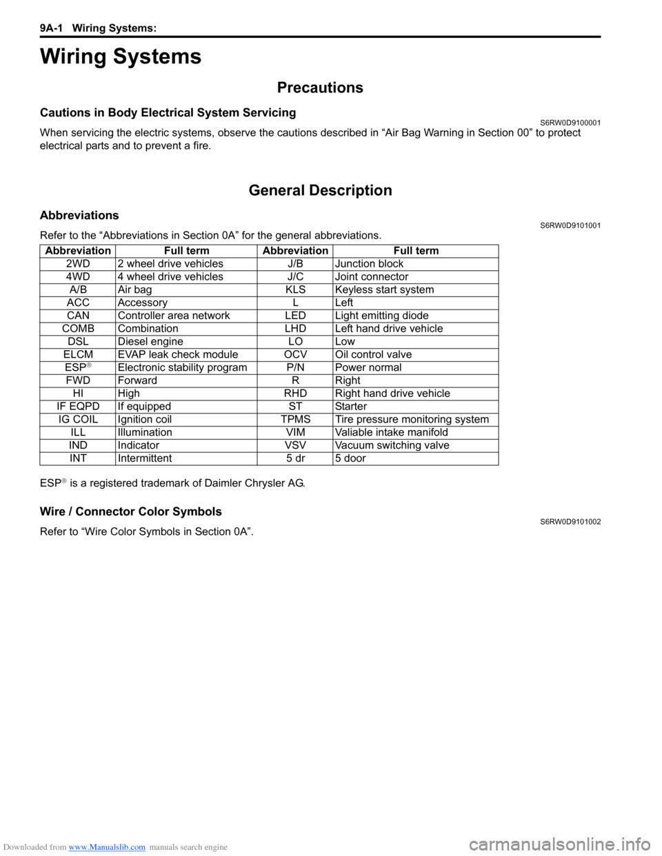
Downloaded from www.Manualslib.com manuals search engine 9A-1 Wiring Systems:
Body, Cab and Accessories
Wiring Systems
Precautions
Cautions in Body Electrical System ServicingS6RW0D9100001
When servicing the electric systems, observe the cautions described in “Air Bag Warning in Section 00” to protect
electrical parts and to prevent a fire.
General Description
AbbreviationsS6RW0D9101001
Refer to the “Abbreviations in Section 0A” for the general abbreviations.
ESP
® is a registered trademark of Daimler Chrysler AG.
Wire / Connector Color SymbolsS6RW0D9101002
Refer to “Wire Color Symbols in Section 0A”. Abbreviation Full term Abbreviation Full term
2WD 2 wheel drive vehicles J/B Junction block
4WD 4 wheel drive vehicles J/C Joint connector
A/B Air bag KLS Keyless start system
ACC Accessory L Left
CAN Controller area network LED Light emitting diode
COMB Combination LHD Left hand drive vehicle
DSL Diesel engine LO Low
ELCM EVAP leak check module OCV Oil control valve
ESP
®Electronic stability program P/N Power normal
FWD Forward R Right
HI High RHD Right hand drive vehicle
IF EQPD If equipped ST Starter
IG COIL Ignition coil TPMS Tire pressure monitoring system
ILL Illumination VIM Valiable intake manifold
IND Indicator VSV Vacuum switching valve
INT Intermittent 5 dr 5 door