2006 SUZUKI SX4 check engine
[x] Cancel search: check enginePage 937 of 1556

Downloaded from www.Manualslib.com manuals search engine Heater and Ventilation: 7A-9
Blower Speed Selector InspectionS6RW0D7106010
Check blower speed selector for each terminal to
terminal continuity. If check result does not meet the
following conditions, replace HVAC control unit.
Air Intake Selector InspectionS6RW0D7106011
• Check that there is continuity between terminal (1)
and terminal (2) when air intake selector is at “FRE”
position.
• Check that there is no continuity between terminal (1)
and terminal (2) when air intake selector is at “REC”
position.
If check result does not meet the above conditions,
replace HVAC control unit.
Air Intake Control Actuator Removal and
Installation
S6RW0D7106012
Removal
1) Disconnect negative cable from battery.
2) Remove glove box from instrument panel.
3) Remove passenger side foot duct (1) from HVAC
unit by removing screw (2). (LH steering vehicle
only.)
4) Disconnect connector (1) from air intake control
actuator (2).
5) Detach linkage rod (3) and remove air intake control
actuator (2) by removing screws (4).
IHMH
GNDLML
PositionTerminalI
OFF
1
2
3
4LMLMHHGND
I4RS0A710019-01
1
2
I5RW0A710007-01
1
2
I7RW01710007-01
3
1
24I7RW01710016-02
Page 938 of 1556

Downloaded from www.Manualslib.com manuals search engine 7A-10 Heater and Ventilation:
Installation
Reverse removal procedure noting the following
instruction.
• Be sure to insert the linkage rod (1) into the hole (2) of
air intake control actuator.Air Intake Control Actuator InspectionS6RW0D7106013
Check air intake control actuator as follows:
1) Using service wire, connect battery positive terminal
to “d” terminal and battery negative terminal to
terminal “a”. And, check if air intake selector link
operates smoothly and it stops at “FRE” position (1).
2) Using service wire, connect battery positive terminal
to “d” terminal and battery negative terminal to
terminal “c”. And, check if air intake selector link
operates smoothly and it stops at “REC” position (2).
3) For auto A/C model, using service wire, connect
battery positive terminal to “d” terminal and battery
negative terminal to “b” terminal. And, check air
intake selector link operates smoothly and it stops at
MIX position (3).
If malfunction is found, replace air intake control
actuator.
21
I7RW01710017-02
4. Motor rotation direction
“a” “b” “c” “d”
1 3
2
4“a”
“b”
“c” “d”
I7RW01710018-05
Page 940 of 1556

Downloaded from www.Manualslib.com manuals search engine 7A-12 Heater and Ventilation:
Rear Duct Removal and Installation (If
Equipped)
S6RW0D7106016
Removal
1) Disconnect negative (–) cable at battery.
2) Remove front seats referring to “Front Seat Removal
and Installation in Section 9G”.
3) Remove console box referring to “Console Box
Components in Section 9H”.
4) Take off carpet till rear ducts is totally exposed.
5) Remove right and left rear ducts.
6) Remove center rear duct as follows, if necessary.
a) Remove HVAC control unit referring to “HVAC
Control Unit Removal and Installation” (non-A/C
or manual A/C) or “HVAC Control Module
Removal and Installation in Section 7B” (auto A/
C).
b) Remove center rear duct from HVAC unit.
Installation
Reverse removal procedure noting the following
instructions.
• Install HVAC control unit referring to “HVAC Control
Unit Removal and Installation” (non-A/C or manual A/
C) or “HVAC Control Module Removal and Installation
in Section 7B” (auto A/C), if removed.
• Install console box referring to “Console Box
Components in Section 9H”.
• Install front seats referring to “Front Seat Removal
and Installation in Section 9G”.
HVAC Air Filter Removal and Installation (If
Equipped)
S6RW0D7106017
Removal
1) Remove glove box from instrument panel.
2) Remove air filter (1) from HVAC unit while releasing
claws (2).
Installation
Reverse removal procedure noting the following
instructions.
• Position air filter by directing its arrow mark to the
upward.
HVAC Air Filter Inspection (If Equipped)S6RW0D7106018
Reference: “HVAC Air Filter Removal and Installation (If
Equipped)”
Check that filter is not excessively dirty, damage or oily,
clean filter with compressed air from air outlet side of
filter. If abnormality is found, replace filter with new one.
1. Center rear duct 4. Clip
2. Right rear duct 5. HVAC unit
3. Left rear duct
324 5
1
4
I7RW01710019-01
12
2
I6RW0C710010-01
I6RW0C710009-01
I4RS0A710032-01
Page 941 of 1556

Downloaded from www.Manualslib.com manuals search engine Air Conditioning System: Manual Type 7B-1
HVAC
Air Conditioning System
Manual Type
Precautions
A/C System CautionS6RW0D7210001
CAUTION!
The A/C system of this vehicle uses HFC-134a (R-134a) refrigerant, specified compressor oil and
specified parts.
Do not use CFC-12 (R-12) refrigerant, R-12 exclusive use compressor oil and R-12 exclusive parts in
this A/C system, do not attempt to use R-12 servicing equipment. Otherwise, use of it will result in
leakage of refrigerant, damage or other faulty condition of A/C system and damage or other faulty
condition of servicing equipment.
When replenishing or changing refrigerant and compressor oil and when replacing parts, make sure
that the material or the part to be used is appropriate to the A/C installed in the vehicle being serviced.
Use of incorrect one will result in leakage of refrigerant, damage in parts or other faulty condition.
Precautions on Servicing A/C SystemS6RW0D7210002
WARNING!
Should refrigerant HFC-134a (R-134a) is exposed to your eye(s), consult a doctor immediately.
• Do not reuse your hand to rub affected eye(s). Instead, use fresh cold water to splash it over
affected area to thus gradually raise its temperature above the freezing point.
• Obtain proper treatment as soon as possible from a doctor or eye specialist. Should liquid
refrigerant HFC-134a (R-134a) is exposed to your skin, such affected part should be treated in the
same manner as when skin is frostbitten or frozen.
Handling Refrigerant HFC-134a (R-134a)
• Always wear goggles to protect your eyes.
• Avoid direct contact to liquid refrigerant.
• Do not heat refrigerant container higher than 40 °C (104 °F).
• Do not discharge refrigerant into atmosphere.
• Do not expose bright metals to liquid refrigerant. Refrigerant combined with moisture is corrosive and tarnishes
surfaces of bright metals including chrome.
• Never use heat for bending pipes. When bending a pipe, try to make its bending angle as smooth as possible.
• Keep internal parts of air conditioning free from moisture and dirt. When disconnecting any line from system, install
a blind plug or cap to the fitting immediately.
• When handling recovery and recycling equipment, be sure to follow the instruction manual for the equipment.
• Check local governmental regulations regarding working with refrigerator systems and its tooling.
• When connecting hoses and pipes, apply a few drops of compressor oil (refrigerant oil) to O-ring.
• Replace O-ring with new one once hoses, pipes and parts disconnected.
• When tightening or loosening a fitting, use two wrenches, one for turning and the other for support.
• Route drain hose so that drained water does not make any contact to vehicle components.
• If pipes or hoses are replaced, replenish specified amount of compressor oil to compressor suction side referring to
“Replenishing Compressor Oil” in “Operation Procedure for Refrigerant Charge”.
Page 949 of 1556

Downloaded from www.Manualslib.com manuals search engine Air Conditioning System: Manual Type 7B-9
10) Check for each pressure of low side and high side if it is within shaded range of graph. If each gauge reading is out
of specified pressure, correct defective part referring to the following table.
When diagnosing troubles of abnormal pressure on the low side and high side for each pressure more specifically,
refer to “Trouble Diagnosis for Abnormal Pressure”.
NOTE
Pressure registered on gauge varies with ambient temperature. Therefore, use the graphs when
determining if pressures are normal or not.
Low side and high side pressure example, Gauges should read as follows when ambient temperature is 30
°C (86 °F)
Pressure on high pressure gauge (HI): 1130 – 1560 kPa (11.4 – 15.6 kgf/cm2)
Pressure on low pressure gauge (LO): 270 – 390 kPa (2.7 – 3.9 kgf/cm2)
High pressure gauge
[A]: Pressure of high pressure gauge [C]: Ambient temperature [E]: Acceptable range
[B]: Pressure of low pressure gauge [D]: Humidity
Condition Possible cause Correction
Pressure is higher than
acceptable range
(“A” area)Refrigerant overcharged Recharge.
Expansion valve frozen or clogged Check expansion valve.
Clogged refrigerant passage of high pressure side Clean or replace.
Condenser cooling fan malfunction (Insufficient
cooling of condenser)Check condenser cooling fan.
Dirty or bent condenser fins (Insufficient cooling of
condenser)Clean or repair.
Compressor malfunction (Insufficient oil etc.) Check compressor.
Engine overheat Check engine cooling system
referring to “Engine Cooling Symptom
Diagnosis in Section 1F”.
22 312.9 2200
0 1 2 3
30 70 30 70%
4 5 6 7 8 9 10
11 12 13
14
15
16
17
18
19 21 298.7 2100
20
14.2 28.4 42.7 56.9 71.1 85.3 99.5 113.8 128.0
142.2
151.4 170.6 184.9
199.1
213.3
227.5
241.7
256.0
270.2
284.4
100 200 300 400 500 600 700 800 900 1000
1100 1200 1300
1400
1500
1600
1700
1800
1900
2000
25 30 35
77 86 95 psi kPa kgf/cm
2
[C] [B] [A]
C
F
“A”
“B”
“C”
[E]
[E]
“D”[D]
I6RW0D721001-01
Page 950 of 1556

Downloaded from www.Manualslib.com manuals search engine 7B-10 Air Conditioning System: Manual Type
Low pressure gauge
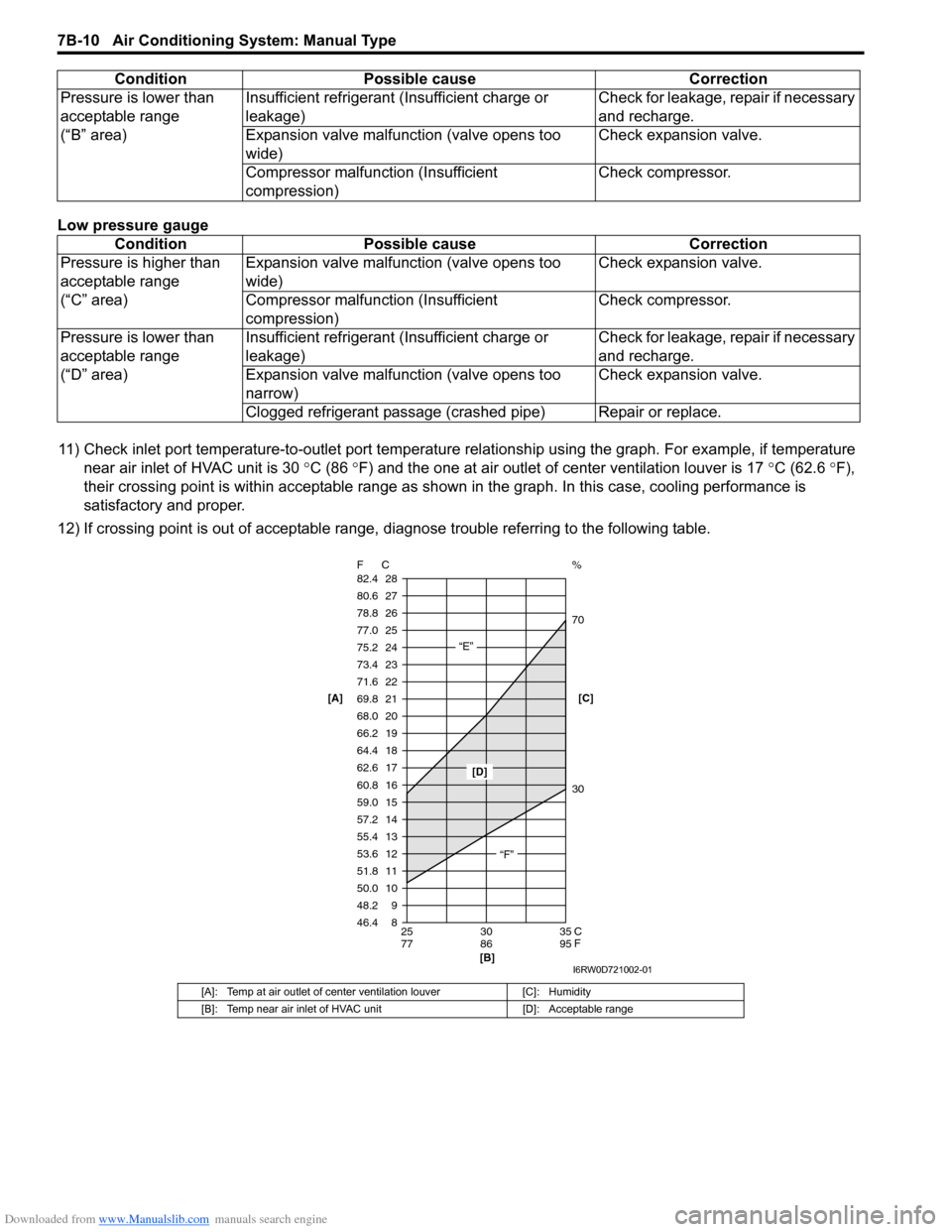
11) Check inlet port temperature-to-outlet port temperature relationship using the graph. For example, if temperature
near air inlet of HVAC unit is 30 °C (86 °F) and the one at air outlet of center ventilation louver is 17 °C (62.6 °F),
their crossing point is within acceptable range as shown in the graph. In this case, cooling performance is
satisfactory and proper.
12) If crossing point is out of acceptable range, diagnose trouble referring to the following table. Pressure is lower than
acceptable range
(“B” area)Insufficient refrigerant (Insufficient charge or
leakage)Check for leakage, repair if necessary
and recharge.
Expansion valve malfunction (valve opens too
wide)Check expansion valve.
Compressor malfunction (Insufficient
compression)Check compressor.
Condition Possible cause Correction
Pressure is higher than
acceptable range
(“C” area)Expansion valve malfunction (valve opens too
wide)Check expansion valve.
Compressor malfunction (Insufficient
compression)Check compressor.
Pressure is lower than
acceptable range
(“D” area)Insufficient refrigerant (Insufficient charge or
leakage)Check for leakage, repair if necessary
and recharge.
Expansion valve malfunction (valve opens too
narrow)Check expansion valve.
Clogged refrigerant passage (crashed pipe) Repair or replace.
[A]: Temp at air outlet of center ventilation louver [C]: Humidity
[B]: Temp near air inlet of HVAC unit [D]: Acceptable range
Condition Possible cause Correction
8 9 10 11 12 13
14 15 16
17 18 19
20 21
22 23
24
25
26
27
28
46.4 48.2 50.0 51.8 53.6 55.4
57.2 59.0 60.8
62.6 64.4 66.2
68.0 69.8
71.6 73.4
75.2
77.0
78.8
80.6
82.4
25 30 35
77 86 95 F C
C
F
“E”
“F”
[D]
[B]
30 70 %
[C] [A]
I6RW0D721002-01
Page 951 of 1556

Downloaded from www.Manualslib.com manuals search engine Air Conditioning System: Manual Type 7B-11
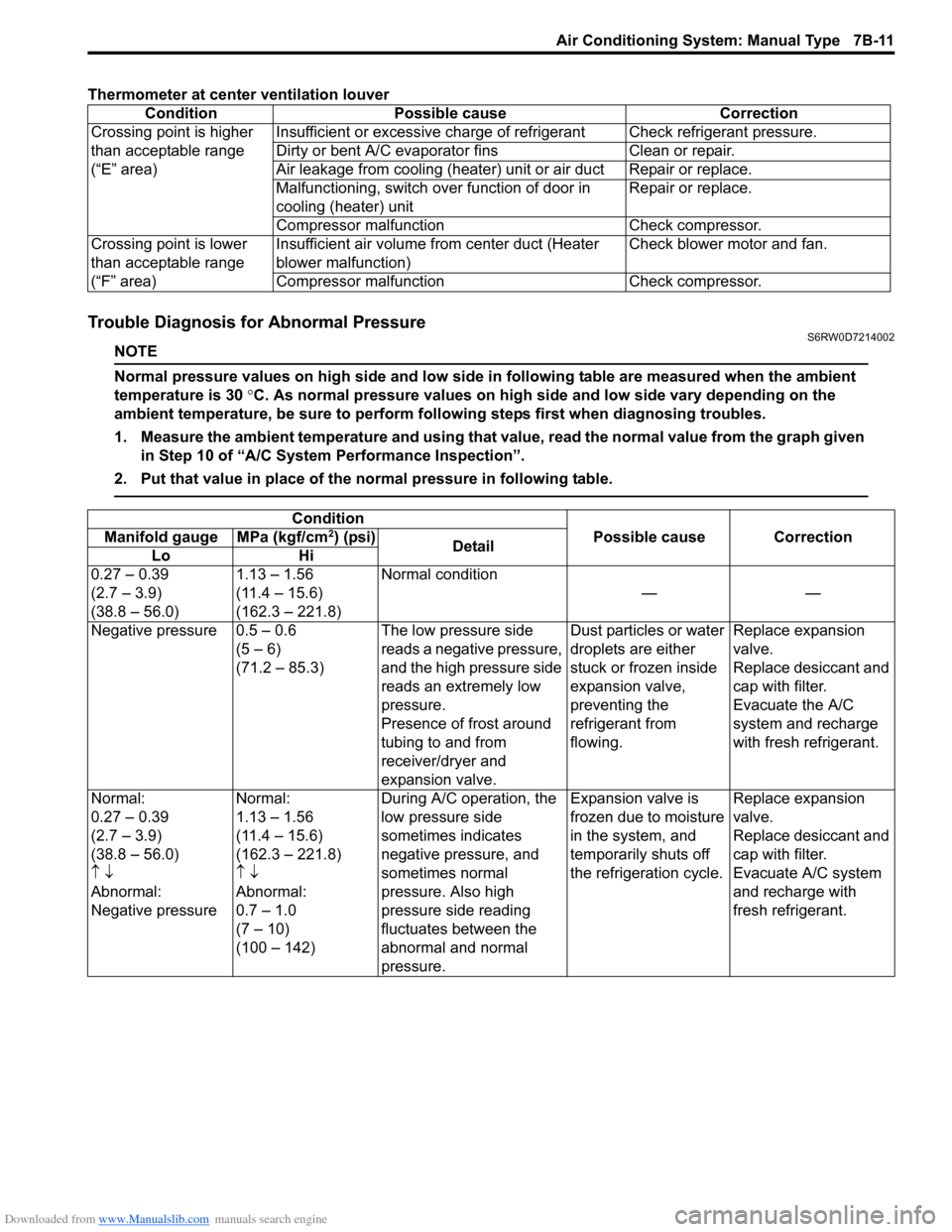
Thermometer at center ventilation louver
Trouble Diagnosis for Abnormal PressureS6RW0D7214002
NOTE
Normal pressure values on high side and low side in following table are measured when the ambient
temperature is 30 °C. As normal pressure values on high side and low side vary depending on the
ambient temperature, be sure to perform following steps first when diagnosing troubles.
1. Measure the ambient temperature and using that value, read the normal value from the graph given
in Step 10 of “A/C System Performance Inspection”.
2. Put that value in place of the normal pressure in following table.
Condition Possible cause Correction
Crossing point is higher
than acceptable range
(“E” area)Insufficient or excessive charge of refrigerant Check refrigerant pressure.
Dirty or bent A/C evaporator fins Clean or repair.
Air leakage from cooling (heater) unit or air duct Repair or replace.
Malfunctioning, switch over function of door in
cooling (heater) unitRepair or replace.
Compressor malfunction Check compressor.
Crossing point is lower
than acceptable range
(“F” area)Insufficient air volume from center duct (Heater
blower malfunction)Check blower motor and fan.
Compressor malfunction Check compressor.
Condition
Possible cause Correction Manifold gauge MPa (kgf/cm2) (psi)
Detail
Lo Hi
0.27 – 0.39
(2.7 – 3.9)
(38.8 – 56.0)1.13 – 1.56
(11.4 – 15.6)
(162.3 – 221.8)Normal condition
——
Negative pressure 0.5 – 0.6
(5 – 6)
(71.2 – 85.3)The low pressure side
reads a negative pressure,
and the high pressure side
reads an extremely low
pressure.
Presence of frost around
tubing to and from
receiver/dryer and
expansion valve.Dust particles or water
droplets are either
stuck or frozen inside
expansion valve,
preventing the
refrigerant from
flowing.Replace expansion
valve.
Replace desiccant and
cap with filter.
Evacuate the A/C
system and recharge
with fresh refrigerant.
Normal:
0.27 – 0.39
(2.7 – 3.9)
(38.8 – 56.0)
↑ ↓
Abnormal:
Negative pressureNormal:
1.13 – 1.56
(11.4 – 15.6)
(162.3 – 221.8)
↑ ↓
Abnormal:
0.7 – 1.0
(7 – 10)
(100 – 142)During A/C operation, the
low pressure side
sometimes indicates
negative pressure, and
sometimes normal
pressure. Also high
pressure side reading
fluctuates between the
abnormal and normal
pressure.Expansion valve is
frozen due to moisture
in the system, and
temporarily shuts off
the refrigeration cycle.Replace expansion
valve.
Replace desiccant and
cap with filter.
Evacuate A/C system
and recharge with
fresh refrigerant.
Page 952 of 1556

Downloaded from www.Manualslib.com manuals search engine 7B-12 Air Conditioning System: Manual Type
A/C System Inspection at ECMS6RW0D7214003
When checking voltage at ECM terminals related to A/C system, refer to “Inspection of ECM and Its Circuits in Section
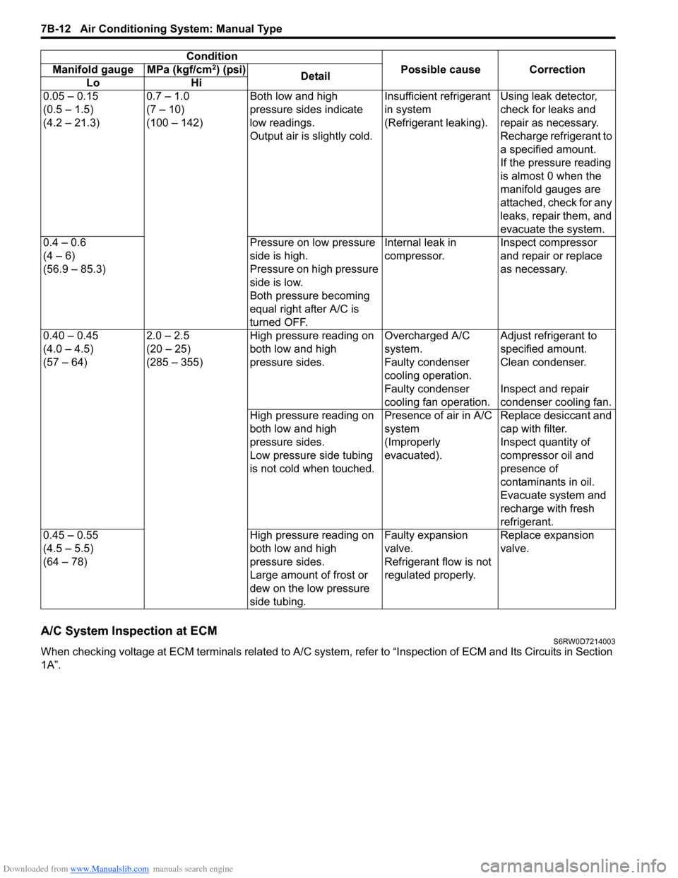
1A”.0.05 – 0.15
(0.5 – 1.5)
(4.2 – 21.3)0.7 – 1.0
(7 – 10)
(100 – 142)Both low and high
pressure sides indicate
low readings.
Output air is slightly cold.Insufficient refrigerant
in system
(Refrigerant leaking).Using leak detector,
check for leaks and
repair as necessary.
Recharge refrigerant to
a specified amount.
If the pressure reading
is almost 0 when the
manifold gauges are
attached, check for any
leaks, repair them, and
evacuate the system.
0.4 – 0.6
(4 – 6)
(56.9 – 85.3)Pressure on low pressure
side is high.
Pressure on high pressure
side is low.
Both pressure becoming
equal right after A/C is
turned OFF.Internal leak in
compressor.Inspect compressor
and repair or replace
as necessary.
0.40 – 0.45
(4.0 – 4.5)
(57 – 64)2.0 – 2.5
(20 – 25)
(285 – 355)High pressure reading on
both low and high
pressure sides.Overcharged A/C
system.Adjust refrigerant to
specified amount.
Faulty condenser
cooling operation.Clean condenser.
Faulty condenser
cooling fan operation.Inspect and repair
condenser cooling fan.
High pressure reading on
both low and high
pressure sides.
Low pressure side tubing
is not cold when touched.Presence of air in A/C
system
(Improperly
evacuated).Replace desiccant and
cap with filter.
Inspect quantity of
compressor oil and
presence of
contaminants in oil.
Evacuate system and
recharge with fresh
refrigerant.
0.45 – 0.55
(4.5 – 5.5)
(64 – 78)High pressure reading on
both low and high
pressure sides.
Large amount of frost or
dew on the low pressure
side tubing.Faulty expansion
valve.
Refrigerant flow is not
regulated properly.Replace expansion
valve. Condition
Possible cause Correction Manifold gauge MPa (kgf/cm
2) (psi)
Detail
Lo Hi