2006 SUZUKI SX4 fuse box connector
[x] Cancel search: fuse box connectorPage 1062 of 1556
Downloaded from www.Manualslib.com manuals search engine 8B-23 Air Bag System:
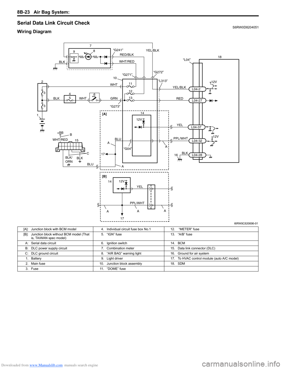
Serial Data Link Circuit CheckS6RW0D8204051
Wiring Diagram
1
2
3
3
18
12V
RED 7
14 9
10
“L313”
“G273”
YEL/BLKL04-2
L04-27 “L04”
PPL/WHT
“G04”L04-3212V
8
GRN
15
+BB
56WHTWHT
4
BLUBLU
BLK
16
11
12
“G241”
13
BLK
L04-28
RED/BLK
WHT/REDYEL/BLK
BLK“G271”
“G272”
WHT/RED
BLK/
ORNBLK
B
C
A A
A
17
[A]
A
[B]
12V
PPL/WHTYEL14
17A
A
YELL04-37
12V
I6RW0C820006-01
[A]: Junction block with BCM model 4. Individual circuit fuse box No.1 12. “METER” fuse
[B]: Junction block without BCM model (That
is, TAIWAN spec model)5. “IGN” fuse 13. “A/B” fuse
A: Serial data circuit 6. Ignition switch 14. BCM
B: DLC power supply circuit 7. Combination meter 15. Data link connector (DLC)
C: DLC ground circuit 8. “AIR BAG” warning light 16. Ground for air system
1. Battery 9. Light driver 17. To HVAC control module (auto A/C model)
2. Main fuse 10. Junction block assembly 18. SDM
3. Fuse 11. “DOME” fuse
Page 1106 of 1556
Downloaded from www.Manualslib.com manuals search engine 8B-67 Air Bag System:
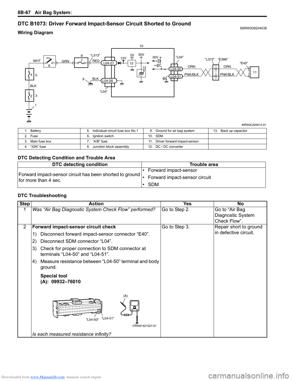
DTC B1073: Driver Forward Impact-Sensor Circuit Shorted to GroundS6RW0D8204036
Wiring Diagram
DTC Detecting Condition and Trouble Area
DTC Troubleshooting
10
“L04”
“L372” “E388”
“E40”
ORN
PNK/BLKORN
PNK/BLKL04-50
L04-5111
30V
“L04”
BLK
L04-28
6 8
7
RED
GRN“L313”L04-27
9
1
2 BLKWHT3
4
5
12
12V5V30V
13
I6RW0C820012-01
1. Battery 5. Individual circuit fuse box No.1 9. Ground for air bag system 13. Back up capacitor
2. Fuse 6. Ignition switch 10. SDM
3. Main fuse box 7. “A/B” fuse 11. Driver forward impact-sensor
4. “IGN” fuse 8. Junction block assembly 12. DC / DC converter
DTC detecting condition Trouble area
Forward impact-sensor circuit has been shorted to ground
for more than 4 sec.• Forward impact-sensor
• Forward impact-sensor circuit
•SDM
Step Action Yes No
1Was “Air Bag Diagnostic System Check Flow” performed?Go to Step 2. Go to “Air Bag
Diagnostic System
Check Flow”.
2Forward impact-sensor circuit check
1) Disconnect forward impact-sensor connector “E40”.
2) Disconnect SDM connector “L04”.
3) Check for proper connection to SDM connector at
terminals “L04-50” and “L04-51”.
4) Measure resistance between “L04-50” terminal and body
ground.
Special tool
(A): 09932–76010
Is each measured resistance infinity?Go to Step 3. Repair short to ground
in defective circuit.
“L04-50”“L04-51”
(A)
I7RW01821027-01
Page 1133 of 1556
Downloaded from www.Manualslib.com manuals search engine Air Bag System: 8B-94
5) Install driver and passenger side front pillar lower
trim.
6) Side-air bag (inflator) model:
Connect yellow connector (1) of side-air bag
(inflator) module by pushing connector till click is
heard from it.
7) Side curtain-air bag (inflator) model:
Connect yellow connector (1) of side curtain-air bag
(inflator) module by pushing connector till click is
heard from it.
8) Install right-side rear quarter lower trim.
9) Install “A/B” fuse to fuse box.
10) Connect negative (–) cable at battery.
11) Turn ignition switch to ON position and verify that
“AIR BAG” warning light flashes 6 times and then
turns OFF. If it does not operate as described,
perform “Air Bag Diagnostic System Check”.
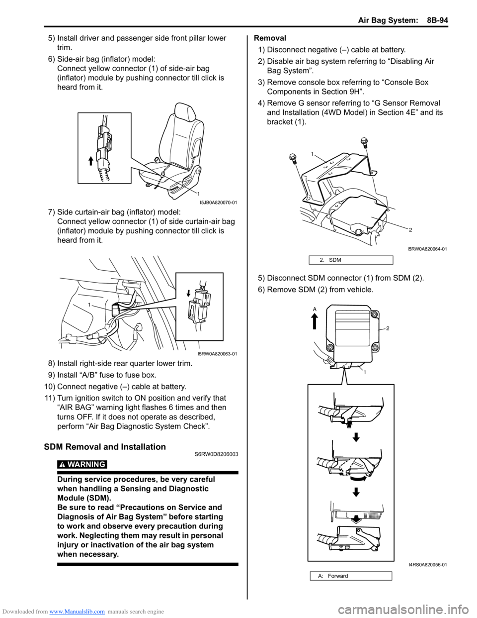
SDM Removal and InstallationS6RW0D8206003
WARNING!
During service procedures, be very careful
when handling a Sensing and Diagnostic
Module (SDM).
Be sure to read “Precautions on Service and
Diagnosis of Air Bag System” before starting
to work and observe every precaution during
work. Neglecting them may result in personal
injury or inactivation of the air bag system
when necessary.
Removal
1) Disconnect negative (–) cable at battery.
2) Disable air bag system referring to “Disabling Air
Bag System”.
3) Remove console box referring to “Console Box
Components in Section 9H”.
4) Remove G sensor referring to “G Sensor Removal
and Installation (4WD Model) in Section 4E” and its
bracket (1).
5) Disconnect SDM connector (1) from SDM (2).
6) Remove SDM (2) from vehicle.
1
I5JB0A820070-01
1
I5RW0A820063-01
2. SDM
A: Forward
1
2
I5RW0A820064-01
2
1
A
I4RS0A820056-01
Page 1161 of 1556
Downloaded from www.Manualslib.com manuals search engine Table of Contents 9- i
9
Section 9
CONTENTS
Body, Cab and Accessories
Precautions ................................................. 9-1
Precautions............................................................. 9-1
Precautions on Body, Cab and Accessories ......... 9-1
Precautions for Body Service ................................ 9-1
Fastener Caution for Body Service ....................... 9-1
Wiring Systems........................................ 9A-1
Precautions........................................................... 9A-1
Cautions in Body Electrical System Servicing..... 9A-1
General Description ............................................. 9A-1
Abbreviations ...................................................... 9A-1
Wire / Connector Color Symbols ......................... 9A-1
Symbols and Marks ............................................ 9A-2
How to Read Connector Layout Diagram ........... 9A-4
How to Read Connector Codes and Terminal
Nos.................................................................... 9A-5
How to Read Ground Point ................................. 9A-8
How to Read Power Supply Diagram.................. 9A-9
How to Read System Circuit Diagram................. 9A-9
Connector Layout Diagram ............................... 9A-11
Connector Layout Diagram ............................... 9A-11
Engine Compartment ........................................ 9A-11
Instrument Panel ............................................... 9A-19
Door, Roof......................................................... 9A-25
Floor .................................................................. 9A-28
Rear .................................................................. 9A-32
Ground Point ...................................................... 9A-33
Ground (earth) Point ......................................... 9A-33
Power Supply Diagram ...................................... 9A-34
Power Supply Diagram ..................................... 9A-34
Fuses and the Protected Parts ......................... 9A-36
Fuses in Main Fuse Box ................................... 9A-36
Individual Circuit Fuse Box No. 1 ...................... 9A-37
Individual Circuit Fuse Box No. 2 (In J/B
(Except Taiwan)) ............................................. 9A-38
Individual Circuit Fuse Box No. 2 (In J/B
(Taiwan)) ......................................................... 9A-40
Junction Block (J/B) Connector / Fuse Layout .. 9A-42
Junction Block Inner Circuit (Overview
(Except Taiwan)) ............................................. 9A-43
Junction Block Inner Circuit (Detail (Except
Taiwan)) .......................................................... 9A-45
Junction Block Inner Circuit (Overview
(Taiwan)) ......................................................... 9A-50Junction Block Inner Circuit (Detail (Taiwan)) ... 9A-52
System Circuit Diagram.....................................9A-57
System Circuit Diagram .................................... 9A-57
A-1 Cranking System Circuit Diagram .............. 9A-58
A-2 Charging System Circuit Diagram .............. 9A-59
A-3 Ignition System Circuit Diagram (M15A
engine, M16A engine) ..................................... 9A-60
A-3 Ignition System Circuit Diagram (J20A
engine) ............................................................ 9A-61
A-4 Cooling System Circuit Diagram (M15A
engine, M16A engine) ..................................... 9A-62
A-4 Cooling System Circuit Diagram (J20A
engine) ............................................................ 9A-63
A-5 Engine and A/C Control System Circuit
Diagram (M15A engine) .................................. 9A-64
A-5 Engine and A/C Control System Circuit
Diagram (M16A engine) .................................. 9A-68
A-5 Engine and A/C Control System Circuit
Diagram (J20A engine) ................................... 9A-72
A-6 A/T Control System Circuit Diagram........... 9A-76
A-7 Immobilizer System Circuit Diagram .......... 9A-78
A-8 Body Control System Circuit Diagram
(Except Taiwan) .............................................. 9A-79
A-8 Body Control System Circuit Diagram
(Taiwan) .......................................................... 9A-83
A-10 4WD Control System (Except Taiwan) ..... 9A-87
B-1 Windshield Wiper and Washer Circuit
Diagram........................................................... 9A-88
B-2 Rear Wiper and Washer Circuit Diagram
(Except Taiwan) .............................................. 9A-89
B-2 Rear Wiper and Washer Circuit Diagram
(Taiwan) .......................................................... 9A-90
B-3 Rear Defogger Circuit Diagram (Except
Taiwan) ........................................................... 9A-91
B-3 Rear Defogger Circuit Diagram (Taiwan) ... 9A-92
B-4 Power Window Circuit Diagram .................. 9A-93
B-5 Power Door Lock Circuit Diagram (Except
Taiwan) ........................................................... 9A-95
B-5 Power Door Lock Circuit Diagram
(Taiwan) .......................................................... 9A-97
B-6 Power Mirror Circuit Diagram (Except
Taiwan) ........................................................... 9A-99
B-6 Power Mirror Circuit Diagram (Taiwan) .... 9A-100
B-7 Horn Circuit Diagram ................................ 9A-101
B-8 Seat Heater Circuit Diagram..................... 9A-102
Page 1212 of 1556
Downloaded from www.Manualslib.com manuals search engine 9A-45 Wiring Systems:
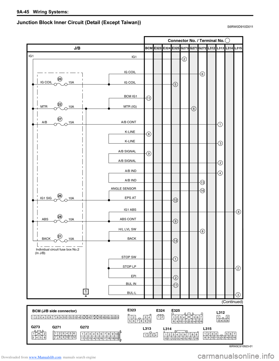
Junction Block Inner Circuit (Detail (Except Taiwan))S6RW0D910D011
BCM (J/B side connector)
3
4
1
25
15 14 12
13 10
11 9 8 67
17
16182122 19
20
23
1234578 116
12 91034 652 1
G271 G273
G272
10
11 12 13 14 15 16 17 18 19123456789
20
345612L312
23414
3
561214 11
10
157 2 11316 9 8 6
5 4 3
2
1
7
11 10
9 8
15
14 13
1216
L313
L315 E325
2 1
123456789
15 16 17 18 11 10 12 13 14 1
234
5
678 910
E323
L314 E324
IG COIL
IG COILIG1
E323 E325E324 BCM G272G271 G273 L312 L313 L314 L315
IG COIL IG1
15A
MTR
10A
A/B
15A
2
6
5
13
J/BConnector No. / Terminal No.
MTR (IG)
A/B CONT
A/B IND
A/B IND
IG1 SIG
10AEPS AT
ABS CONT
STOP SW
STOP LP
EPI
BUL IN
BUL-LBACK H/L LVL SW
BCM IG111
6
1
4
2
A/B SIGNAL
A/B SIGNAL9
3
K-LINE
K-LINE8
12
9
14
2
3
1
2
11
8
ABS
10A
BACK
10A
ANGLE SENSOR
IG1 ABS16
8
1
(Continued)
Individual circuit fuse box No.2
(In J/B)
20
22
27
26
28
21
I6RW0C910923-01
Page 1213 of 1556
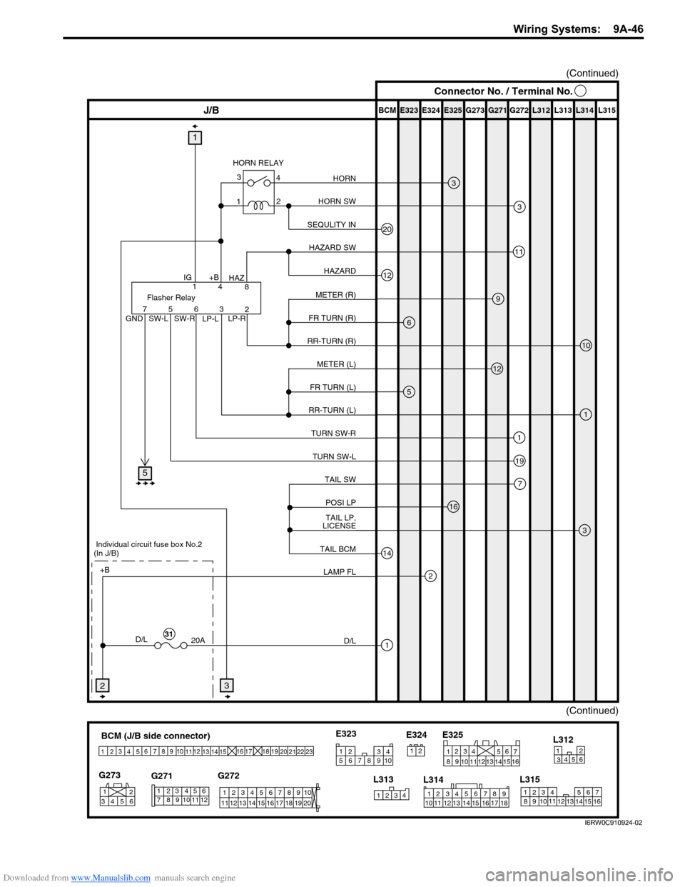
Downloaded from www.Manualslib.com manuals search engine Wiring Systems: 9A-46
BCM (J/B side connector)
3
4
1
25
15 14 12
13 10
11 9 8 67
17
16182122 19
20
23
1234578 116
12 91034 652 1
G271 G273
G272
10
11 12 13 14 15 16 17 18 19123456789
20
345612L312
23414
3
561214 11
10
157 2 11316 9 8 6
5 4 3
2
1
7
11 10
9 8
15
14 13
1216
L313
L315 E325
2 1
123456789
15 16 17 18 11 10 12 13 14 1
234
5
678 910
E323
L314 E324
E323 E325E324 BCM G272G271 G273 L312 L313 L314 L315
11
J/B
Flasher Relay14
8
2 3 6 5 7
3
6
9
3
12
1
5
1
19
3
7
16
2
1
10
1
HORN SW HORN RELAY
GND
SW-L SW-R
LP-LLP-R IG
+B
HAZHORN
HAZARD SW
METER (R)
FR TURN (R)
METER (L) RR-TURN (R)
FR TURN (L)
RR-TURN (L)
TURN SW-R
TAIL SW TURN SW-L
POSI LP
TAIL LP,
LICENSE
LAMP FL +B
D/L
20A
D/L
12HAZARD
20SEQULITY IN
14TAIL BCM
32
(Continued)
Individual circuit fuse box No.2
(In J/B)
31
(Continued)
4 3
2
1
5
Connector No. / Terminal No.
I6RW0C910924-02
Page 1214 of 1556
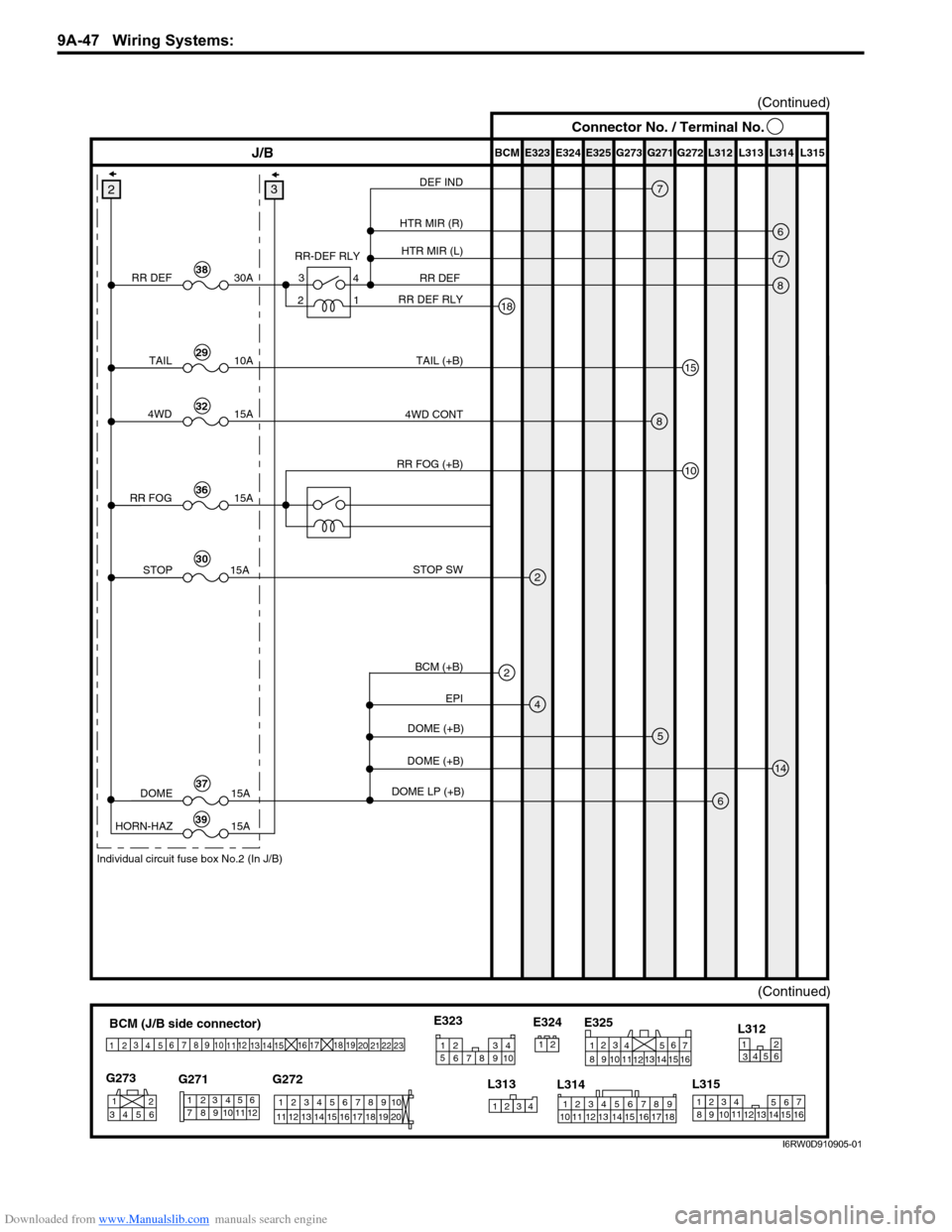
Downloaded from www.Manualslib.com manuals search engine 9A-47 Wiring Systems:
E323 E325E324 BCM G272G271 G273 L312 L313 L314 L315J/B
7
18
8
5
4
14
6
3
(Continued)
DEF IND
RR DEF
6HTR MIR (R)
7HTR MIR (L)
RR DEF RLY RR-DEF RLY
EPI STOP SW
DOME (+B)
DOME (+B)
DOME LP (+B)
15
10
TAIL (+B)
RR DEF
DOME
HORN-HAZ30A
15A
15A
2
38
TAIL10A29
84WD CONT
RR FOG (+B)4WD15A32
2STOP 15A30
37
39
(Continued)
Individual circuit fuse box No.2 (In J/B)
4 3
1
2
RR FOG15A36
Connector No. / Terminal No.
BCM (J/B side connector)
3
4
1
25
15 14 12
13 10
11 9 8 67
17
16182122 19
20
23
1234578 116
12 91034 652 1
G271 G273
G272
10
11 12 13 14 15 16 17 18 19123456789
20
345612L312
23414
3
561214 11
10
157 2 11316 9 8 6
5 4 3
2
1
7
11 10
9 8
15
14 13
1216
L313
L315 E325
2 1
123456789
15 16 17 18 11 10 12 13 14 1
234
5
678 910
E323
L314 E324
2BCM (+B)
I6RW0D910905-01
Page 1215 of 1556
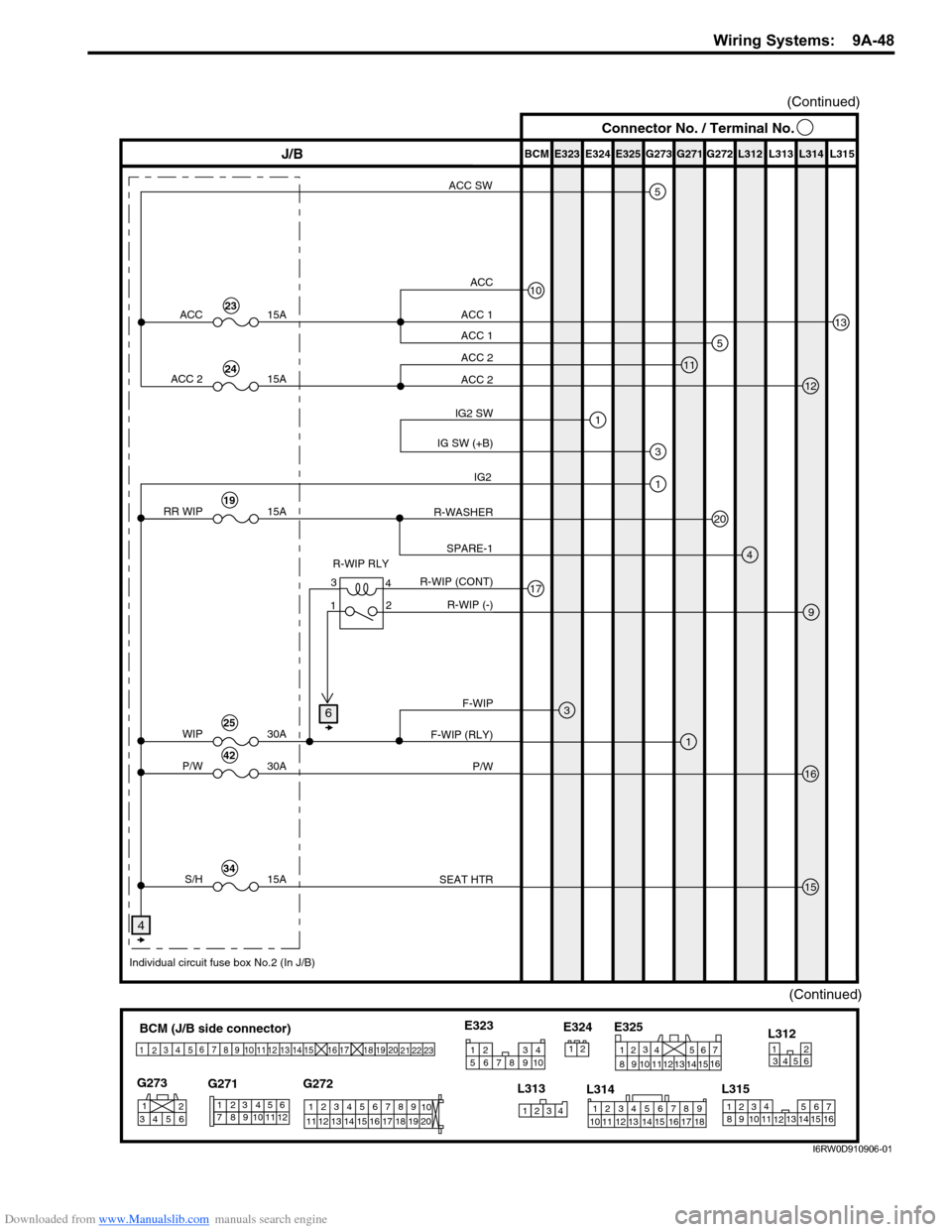
Downloaded from www.Manualslib.com manuals search engine Wiring Systems: 9A-48
(Continued)
BCM (J/B side connector)
3
4
1
25
15 14 12
13 10
11 9 8 67
17
16182122 19
20
23
1234578 116
12 91034 652 1
G271 G273
G272
10
11 12 13 14 15 16 17 18 19123456789
20
345612L312
23414
3
561214 11
10
157 2 11316 9 8 6
5 4 3
2
1
7
11 10
9 8
15
14 13
1216
L313
L315 E325
2 1
123456789
15 16 17 18 11 10 12 13 14 1
234
5
678 910
E323
L314 E324
E323 E325E324 BCM G272G271 G273 L312 L313 L314 L315
9
J/B
11
10
13
12
3
1
17
1
1
3
16
15
ACC 1
ACC
ACC 2
5ACC 1
ACC 2
IG2 SW
R-WIP RLY
F-WIP
F-WIP (RLY)
P/W
IG SW (+B)
R-WIP (CONT)
R-WIP (-)
4SPARE-1
ACC
P/W15A
ACC 2 15A
30A
WIP 30A
(Continued)
23
24
25
20R-WASHERRR WIP 15A19
42
SEAT HTRS/H 15A34
Individual circuit fuse box No.2 (In J/B)
5ACC SW
4
4 3
2
1
Connector No. / Terminal No.
6
IG2
I6RW0D910906-01