2006 SUZUKI SX4 Engine Cooling System
[x] Cancel search: Engine Cooling SystemPage 945 of 1556
![SUZUKI SX4 2006 1.G Service Workshop Manual Downloaded from www.Manualslib.com manuals search engine Air Conditioning System: Manual Type 7B-5
A/C System Wiring DiagramS6RW0D7212002
[A]
7
WHT
GRN5YELBLK
3
G154-3
G154-4
G154-7
G154-8
G154-10
G15 SUZUKI SX4 2006 1.G Service Workshop Manual Downloaded from www.Manualslib.com manuals search engine Air Conditioning System: Manual Type 7B-5
A/C System Wiring DiagramS6RW0D7212002
[A]
7
WHT
GRN5YELBLK
3
G154-3
G154-4
G154-7
G154-8
G154-10
G15](/manual-img/20/7612/w960_7612-944.png)
Downloaded from www.Manualslib.com manuals search engine Air Conditioning System: Manual Type 7B-5
A/C System Wiring DiagramS6RW0D7212002
[A]
7
WHT
GRN5YELBLK
3
G154-3
G154-4
G154-7
G154-8
G154-10
G154-13
G154-5
G154-6
G155-5
G155-2
G155-3
G155-7
G155-6
G155-1
G154-9
G154-14
BLK/WHT
YEL
BLU/WHT
RED
BRN
GRN/WHT
RED/BLK
RED
GRN
GRN/YEL
RED/YEL
RED/BLU
20
21
23 22
BLK/RED
6 2
MBLK/WHTBLK/YEL
M
11
4RED/YEL 1
E01-49
12
E01-16
GRY 13
12V
BLU/WHTE01-3510
E01-48
18
19RED/BLK
BLK/RED
BLK/RED
BRN/WHTE01-60
E01-1
E01-29BLK/WHT
M
BLU/YELBLK/YEL
5V5V 5V
WHT/BLK
9
ORN
14E01-36
C01-12C01-14GRY/REDRED/BLU
E01-41
RED/BLK
RED
WHT
8
BLK
BLK/ORN
BLU IG1
IG2
5V
17
28
29
31
2726 2524
16
16
30
34
33E01-4 E01-19WHTRED
C01-50C01-49WHTRED
32
LT GRN
C01-57
C01-2415
GRY/BLU5V
I6RW0C721002-01
[A]: Illumination control model 9. A/C refrigerant pressure
sensor18. Condenser cooling fan relay 27. Illumination light
1. Ignition switch 10. ECM 19. Condenser cooling fan motor 28. Rear defogger relay
2. Blower motor 11. Air intake control actuator 20. Blower speed selector 29. Rear defogger
3. HVAC control unit 12. Compressor relay 21. A/C switch 30. Main relay
4. Lighting switch 13. Compressor 22. Air intake selector 31. Tail light
5. Blower motor relay 14. Evaporator temperature
sensor23. Rear defogger switch 32. TCM
6. Blower motor resistor 15. ECT sensor 24. “A/C” indicator light 33. To other control module and DLC
7. Junction block assembly 16. To BCM 25. “REC” indicator light 34. ABS control module
8. BCM 17. Main fuse box 26. Rear defogger indicator
Page 946 of 1556

Downloaded from www.Manualslib.com manuals search engine 7B-6 Air Conditioning System: Manual Type
Component Location
A/C System Major Components LocationS6RW0D7213001
7
8
2435
69
9
(a)
(a)
(a)
(b)
(b)
(c)
1
I7RW01721004-03
1. HVAC unit 6. Discharge hose : 25 N⋅m (2.5 kgf-m, 18.0 lb-ft)
2. Compressor 7. Suction hose : 3.5 N⋅m (0.35 kgf-m, 2.51 lb-ft)
3. Condenser assembly 8. Liquid pipe : Apply compressor oil to O-ring.
4. Condenser cooling fan 9. Expansion valve
5. Receiver/dryer : 11 N⋅m (1.1 kgf-m, 8.0 lb-ft)
Page 947 of 1556

Downloaded from www.Manualslib.com manuals search engine Air Conditioning System: Manual Type 7B-7
Electronic Control System Components LocationS6RW0D7213002
NOTE
The figure shows left-hand steering vehicle. For right-hand steering vehicle, parts with (*) are installed
at the opposite side.
[A]
8*
9* 10*
11
1
5
7*
6
7*
12
13
14
1715
1642
3
I6RW0C721003-01
[A]: Junction block assembly viewed from relay side 6. Blower motor relay 12. Air intake selector
1. A/C refrigerant pressure sensor 7. Junction block assembly 13. Rear defogger switch
2. Compressor relay 8. Air intake actuator 14. Temperature selector
3. Condenser cooling fan relay 9. Blower motor 15. Blower speed selector
4. ECT sensor 10. Blower motor resistor 16. Air flow selector
5. Condenser cooling fan 11. HVAC control unit 17. A/C switch
Page 948 of 1556

Downloaded from www.Manualslib.com manuals search engine 7B-8 Air Conditioning System: Manual Type
Diagnostic Information and Procedures
A/C System Performance InspectionS6RW0D7214001
1) Confirm that vehicle and environmental conditions
are as follows.
• Vehicle is put indoors.
• Ambient temperature is within 25 – 35 °C (77 – 95
°F).
• Relative humidity is within 30 – 70%.
• There is no wind indoors.
• HVAC unit is normal.
• Blower motor is normal.
• There is no air leakage from air ducts.
• Condenser fins are clean.
• HVAC air filter is not clogged with dirt and dust (if
equipped).
• Battery voltage is about 12 V.
• Radiator cooling fan operates normally.
2) Make sure that high pressure valve (1) and low
pressure valve (2) of manifold gauge are firmly
closed.
3) Connect high pressure charging hose (3) to high
pressure service valve (5) on vehicle and low
pressure charging hose (4) to low pressure service
valve (6).
4) Bleed the air in charging hoses (3) and (4) by
loosening their nuts respectively utilizing the
refrigerant pressure. When a hissing sound is heard,
immediately tighten nut.
CAUTION!
Do not connect high and low pressure
charging hoses in reverse.
5) Warm up engine to the normal operating
temperature and keep it at the specified idle speed.
6) Turn A/C switch ON, set blower speed selector at
maximum speed position, temperature selector at
maximum cold position, air flow selector at face
position, and air intake selector at recirculation
position. (Confirm that A/C compressor, A/C
condenser cooling fan and radiator cooling fan are
working.)
7) Wait for ten minutes to stabilize the A/C operation.
8) Open all door windows, front doors and engine hood.
9) With about 20 mm (0.8 in.) of dry bulb thermometer
(1) put right in front of center ventilation louver and a
wet and dry bulb thermometer (2) near air inlet of
HVAC unit.
321
4
6
5
I7RW01721006-01
2
1
I5RW0A721008-01
Page 949 of 1556

Downloaded from www.Manualslib.com manuals search engine Air Conditioning System: Manual Type 7B-9
10) Check for each pressure of low side and high side if it is within shaded range of graph. If each gauge reading is out
of specified pressure, correct defective part referring to the following table.
When diagnosing troubles of abnormal pressure on the low side and high side for each pressure more specifically,
refer to “Trouble Diagnosis for Abnormal Pressure”.
NOTE
Pressure registered on gauge varies with ambient temperature. Therefore, use the graphs when
determining if pressures are normal or not.
Low side and high side pressure example, Gauges should read as follows when ambient temperature is 30
°C (86 °F)
Pressure on high pressure gauge (HI): 1130 – 1560 kPa (11.4 – 15.6 kgf/cm2)
Pressure on low pressure gauge (LO): 270 – 390 kPa (2.7 – 3.9 kgf/cm2)
High pressure gauge
[A]: Pressure of high pressure gauge [C]: Ambient temperature [E]: Acceptable range
[B]: Pressure of low pressure gauge [D]: Humidity
Condition Possible cause Correction
Pressure is higher than
acceptable range
(“A” area)Refrigerant overcharged Recharge.
Expansion valve frozen or clogged Check expansion valve.
Clogged refrigerant passage of high pressure side Clean or replace.
Condenser cooling fan malfunction (Insufficient
cooling of condenser)Check condenser cooling fan.
Dirty or bent condenser fins (Insufficient cooling of
condenser)Clean or repair.
Compressor malfunction (Insufficient oil etc.) Check compressor.
Engine overheat Check engine cooling system
referring to “Engine Cooling Symptom
Diagnosis in Section 1F”.
22 312.9 2200
0 1 2 3
30 70 30 70%
4 5 6 7 8 9 10
11 12 13
14
15
16
17
18
19 21 298.7 2100
20
14.2 28.4 42.7 56.9 71.1 85.3 99.5 113.8 128.0
142.2
151.4 170.6 184.9
199.1
213.3
227.5
241.7
256.0
270.2
284.4
100 200 300 400 500 600 700 800 900 1000
1100 1200 1300
1400
1500
1600
1700
1800
1900
2000
25 30 35
77 86 95 psi kPa kgf/cm
2
[C] [B] [A]
C
F
“A”
“B”
“C”
[E]
[E]
“D”[D]
I6RW0D721001-01
Page 950 of 1556

Downloaded from www.Manualslib.com manuals search engine 7B-10 Air Conditioning System: Manual Type
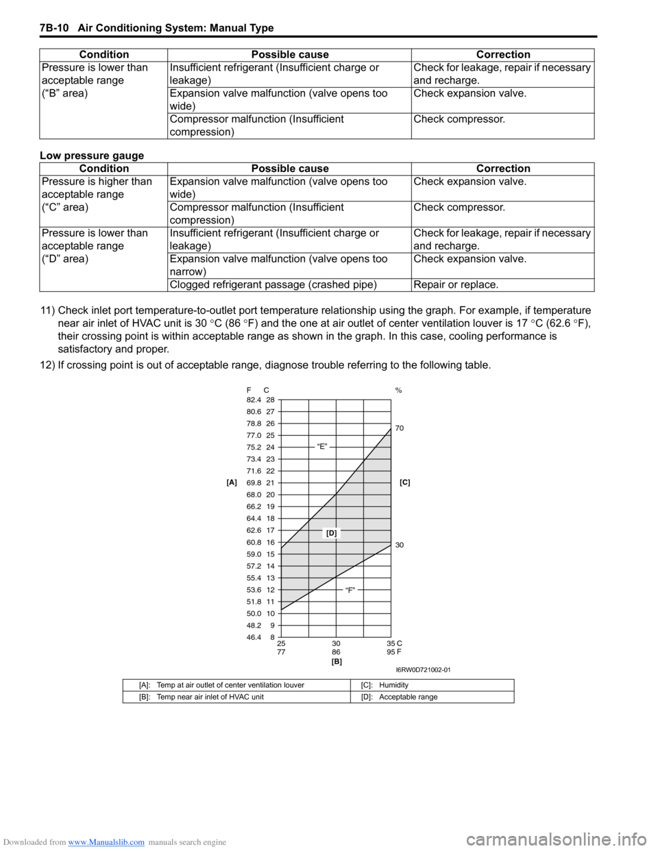
Low pressure gauge
11) Check inlet port temperature-to-outlet port temperature relationship using the graph. For example, if temperature
near air inlet of HVAC unit is 30 °C (86 °F) and the one at air outlet of center ventilation louver is 17 °C (62.6 °F),
their crossing point is within acceptable range as shown in the graph. In this case, cooling performance is
satisfactory and proper.
12) If crossing point is out of acceptable range, diagnose trouble referring to the following table. Pressure is lower than
acceptable range
(“B” area)Insufficient refrigerant (Insufficient charge or
leakage)Check for leakage, repair if necessary
and recharge.
Expansion valve malfunction (valve opens too
wide)Check expansion valve.
Compressor malfunction (Insufficient
compression)Check compressor.
Condition Possible cause Correction
Pressure is higher than
acceptable range
(“C” area)Expansion valve malfunction (valve opens too
wide)Check expansion valve.
Compressor malfunction (Insufficient
compression)Check compressor.
Pressure is lower than
acceptable range
(“D” area)Insufficient refrigerant (Insufficient charge or
leakage)Check for leakage, repair if necessary
and recharge.
Expansion valve malfunction (valve opens too
narrow)Check expansion valve.
Clogged refrigerant passage (crashed pipe) Repair or replace.
[A]: Temp at air outlet of center ventilation louver [C]: Humidity
[B]: Temp near air inlet of HVAC unit [D]: Acceptable range
Condition Possible cause Correction
8 9 10 11 12 13
14 15 16
17 18 19
20 21
22 23
24
25
26
27
28
46.4 48.2 50.0 51.8 53.6 55.4
57.2 59.0 60.8
62.6 64.4 66.2
68.0 69.8
71.6 73.4
75.2
77.0
78.8
80.6
82.4
25 30 35
77 86 95 F C
C
F
“E”
“F”
[D]
[B]
30 70 %
[C] [A]
I6RW0D721002-01
Page 951 of 1556

Downloaded from www.Manualslib.com manuals search engine Air Conditioning System: Manual Type 7B-11
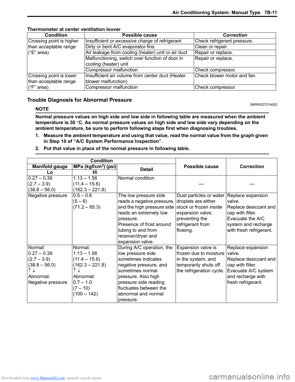
Thermometer at center ventilation louver
Trouble Diagnosis for Abnormal PressureS6RW0D7214002
NOTE
Normal pressure values on high side and low side in following table are measured when the ambient
temperature is 30 °C. As normal pressure values on high side and low side vary depending on the
ambient temperature, be sure to perform following steps first when diagnosing troubles.
1. Measure the ambient temperature and using that value, read the normal value from the graph given
in Step 10 of “A/C System Performance Inspection”.
2. Put that value in place of the normal pressure in following table.
Condition Possible cause Correction
Crossing point is higher
than acceptable range
(“E” area)Insufficient or excessive charge of refrigerant Check refrigerant pressure.
Dirty or bent A/C evaporator fins Clean or repair.
Air leakage from cooling (heater) unit or air duct Repair or replace.
Malfunctioning, switch over function of door in
cooling (heater) unitRepair or replace.
Compressor malfunction Check compressor.
Crossing point is lower
than acceptable range
(“F” area)Insufficient air volume from center duct (Heater
blower malfunction)Check blower motor and fan.
Compressor malfunction Check compressor.
Condition
Possible cause Correction Manifold gauge MPa (kgf/cm2) (psi)
Detail
Lo Hi
0.27 – 0.39
(2.7 – 3.9)
(38.8 – 56.0)1.13 – 1.56
(11.4 – 15.6)
(162.3 – 221.8)Normal condition
——
Negative pressure 0.5 – 0.6
(5 – 6)
(71.2 – 85.3)The low pressure side
reads a negative pressure,
and the high pressure side
reads an extremely low
pressure.
Presence of frost around
tubing to and from
receiver/dryer and
expansion valve.Dust particles or water
droplets are either
stuck or frozen inside
expansion valve,
preventing the
refrigerant from
flowing.Replace expansion
valve.
Replace desiccant and
cap with filter.
Evacuate the A/C
system and recharge
with fresh refrigerant.
Normal:
0.27 – 0.39
(2.7 – 3.9)
(38.8 – 56.0)
↑ ↓
Abnormal:
Negative pressureNormal:
1.13 – 1.56
(11.4 – 15.6)
(162.3 – 221.8)
↑ ↓
Abnormal:
0.7 – 1.0
(7 – 10)
(100 – 142)During A/C operation, the
low pressure side
sometimes indicates
negative pressure, and
sometimes normal
pressure. Also high
pressure side reading
fluctuates between the
abnormal and normal
pressure.Expansion valve is
frozen due to moisture
in the system, and
temporarily shuts off
the refrigeration cycle.Replace expansion
valve.
Replace desiccant and
cap with filter.
Evacuate A/C system
and recharge with
fresh refrigerant.
Page 952 of 1556

Downloaded from www.Manualslib.com manuals search engine 7B-12 Air Conditioning System: Manual Type
A/C System Inspection at ECMS6RW0D7214003
When checking voltage at ECM terminals related to A/C system, refer to “Inspection of ECM and Its Circuits in Section
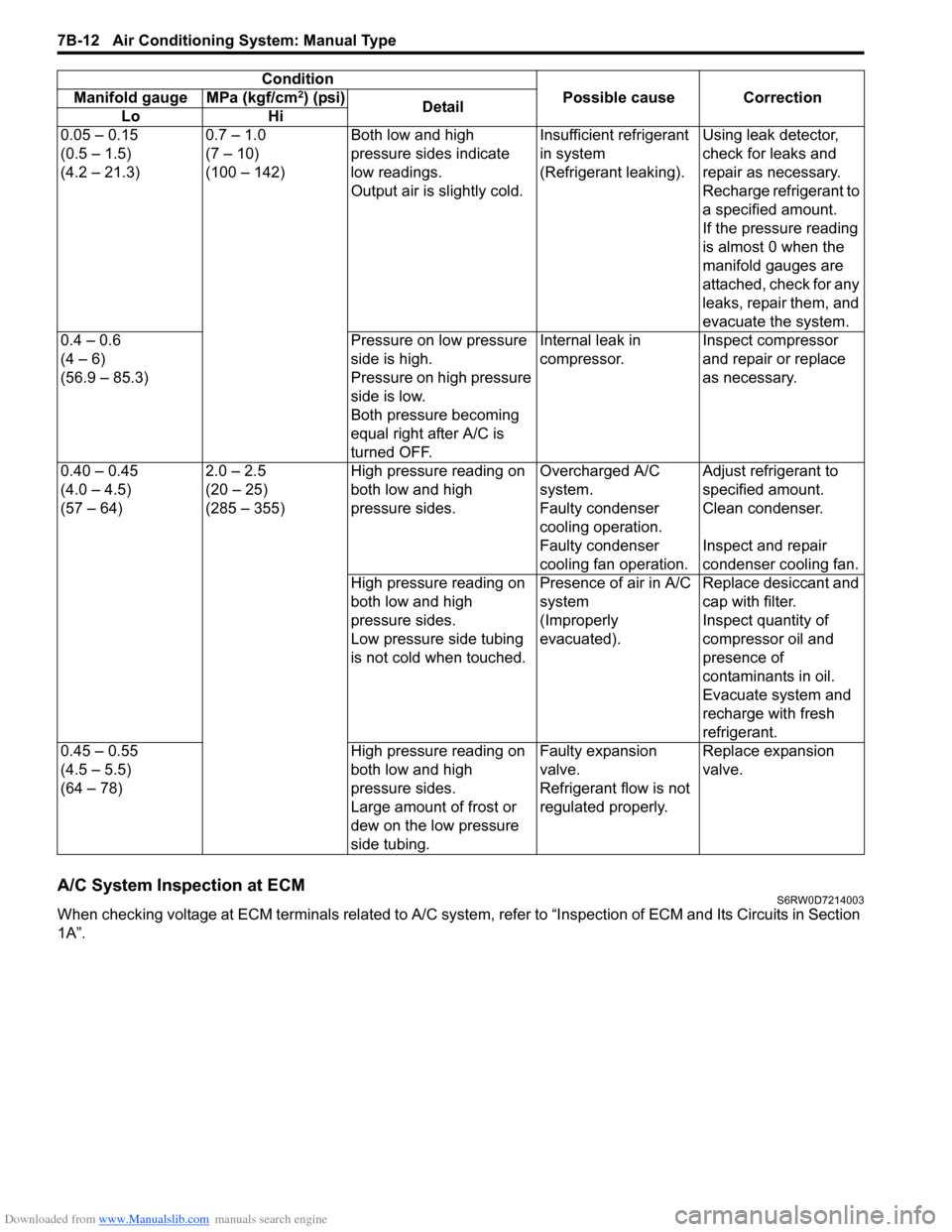
1A”.0.05 – 0.15
(0.5 – 1.5)
(4.2 – 21.3)0.7 – 1.0
(7 – 10)
(100 – 142)Both low and high
pressure sides indicate
low readings.
Output air is slightly cold.Insufficient refrigerant
in system
(Refrigerant leaking).Using leak detector,
check for leaks and
repair as necessary.
Recharge refrigerant to
a specified amount.
If the pressure reading
is almost 0 when the
manifold gauges are
attached, check for any
leaks, repair them, and
evacuate the system.
0.4 – 0.6
(4 – 6)
(56.9 – 85.3)Pressure on low pressure
side is high.
Pressure on high pressure
side is low.
Both pressure becoming
equal right after A/C is
turned OFF.Internal leak in
compressor.Inspect compressor
and repair or replace
as necessary.
0.40 – 0.45
(4.0 – 4.5)
(57 – 64)2.0 – 2.5
(20 – 25)
(285 – 355)High pressure reading on
both low and high
pressure sides.Overcharged A/C
system.Adjust refrigerant to
specified amount.
Faulty condenser
cooling operation.Clean condenser.
Faulty condenser
cooling fan operation.Inspect and repair
condenser cooling fan.
High pressure reading on
both low and high
pressure sides.
Low pressure side tubing
is not cold when touched.Presence of air in A/C
system
(Improperly
evacuated).Replace desiccant and
cap with filter.
Inspect quantity of
compressor oil and
presence of
contaminants in oil.
Evacuate system and
recharge with fresh
refrigerant.
0.45 – 0.55
(4.5 – 5.5)
(64 – 78)High pressure reading on
both low and high
pressure sides.
Large amount of frost or
dew on the low pressure
side tubing.Faulty expansion
valve.
Refrigerant flow is not
regulated properly.Replace expansion
valve. Condition
Possible cause Correction Manifold gauge MPa (kgf/cm
2) (psi)
Detail
Lo Hi