Page 497 of 1556
Downloaded from www.Manualslib.com manuals search engine Drive Shaft / Axle: Rear 3A-18
Specifications
Tightening Torque SpecificationsS6RW0D3127001
NOTE
The specified tightening torque is also described in the following.
“Rear Drive Shaft Components”
Reference:
For the tightening torque of fastener not specified in this section, refer to “Fasteners Information in Section 0A”.
Special Tools and Equipment
Recommended Service MaterialS6RW0D3128001
NOTE
Required service material is also described in the following.
“Rear Drive Shaft Components”
Special ToolS6RW0D3128002
09913–84510 09943–57021
Bearing installer Pliers, Low-Profile Clamp
�)�)
Page 498 of 1556

Downloaded from www.Manualslib.com manuals search engine 3B-1 Differential:
Driveline / Axle
Differential
Precautions
Precaution for Rear Differential Oil LeakageS6RW0D3200001
Whenever vehicle is hoisted for any other service work than oil change, also be sure to check for oil leakage.
Precautions in Diagnosing TroubleS6RW0D3200002
• Do not disconnect the following parts before confirming diagnostic information (DTC, etc.) stored in 4WD control
module memory. These actions will erase memorized information in 4WD control module memory.
– Disconnection of coupler from 4WD control module
– Disconnection of battery cable from battery
– Disconnection of ground wire harness of 4WD control module
– Disconnect main fuse from fuse box
• Diagnostic information stored in 4WD control module memory can be cleared as well as checked by using SUZUKI
scan tool. Before using scan tool, read its Operator’s (Instruction) Manual carefully to have good understanding as
to what functions are available and how to use it.
• Be sure to read “Precautions for Electrical Circuit Service:” before inspection and observe what is written there.
Page 499 of 1556

Downloaded from www.Manualslib.com manuals search engine Differential: 3B-2
General Description
Rear Differential DescriptionS6RW0D3201001
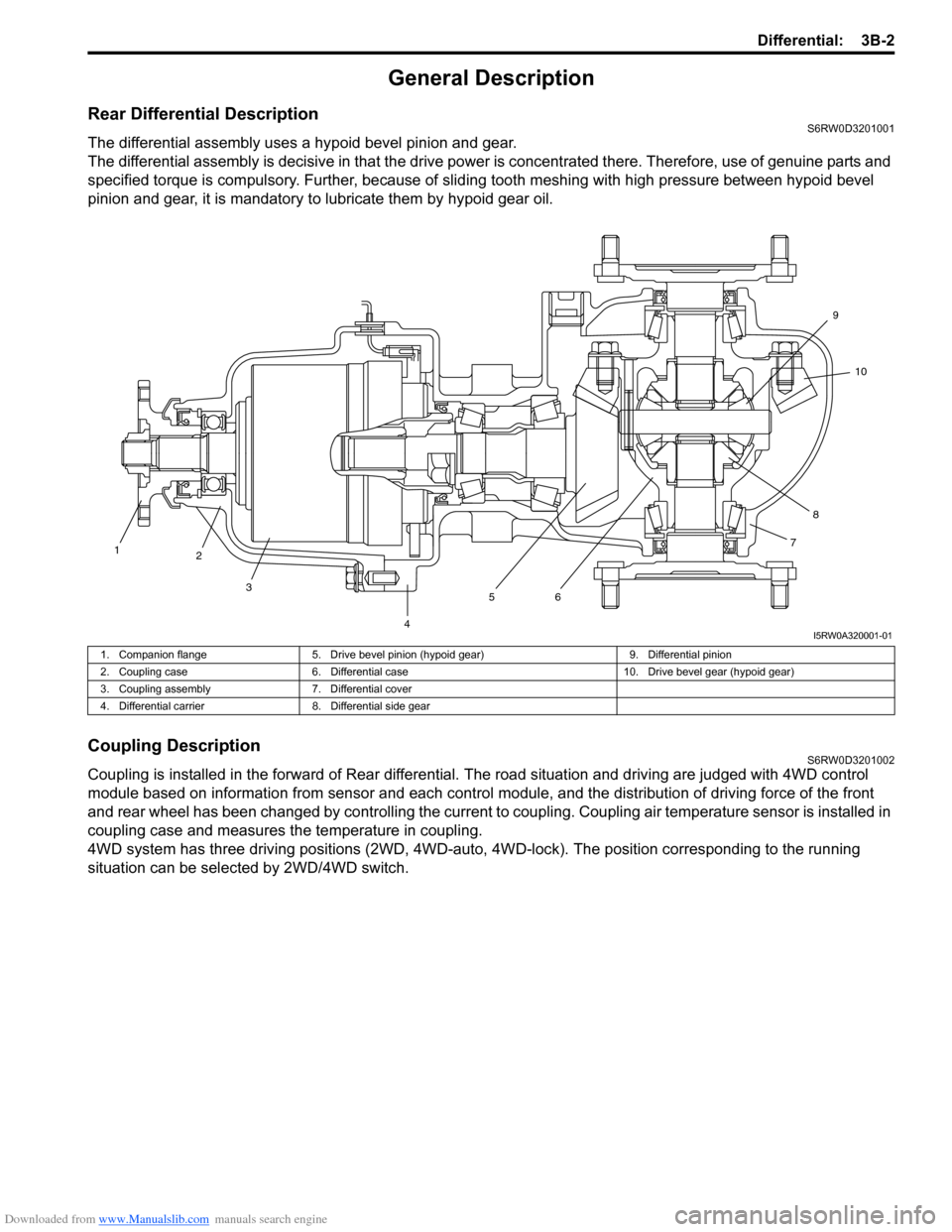
The differential assembly uses a hypoid bevel pinion and gear.
The differential assembly is decisive in that the drive power is concentrated there. Therefore, use of genuine parts and
specified torque is compulsory. Further, because of sliding tooth meshing with high pressure between hypoid bevel
pinion and gear, it is mandatory to lubricate them by hypoid gear oil.
Coupling DescriptionS6RW0D3201002
Coupling is installed in the forward of Rear differential. The road situation and driving are judged with 4WD control
module based on information from sensor and each control module, and the distribution of driving force of the front
and rear wheel has been changed by controlling the current to coupling. Coupling air temperature sensor is installed in
coupling case and measures the temperature in coupling.
4WD system has three driving positions (2WD, 4WD-auto, 4WD-lock). The position corresponding to the running
situation can be selected by 2WD/4WD switch.
1
2
3
4567810 9
I5RW0A320001-01
1. Companion flange 5. Drive bevel pinion (hypoid gear) 9. Differential pinion
2. Coupling case 6. Differential case 10. Drive bevel gear (hypoid gear)
3. Coupling assembly 7. Differential cover
4. Differential carrier 8. Differential side gear
Page 500 of 1556
Downloaded from www.Manualslib.com manuals search engine 3B-3 Differential:
4WD Control System ComponentsS6RW0D3201003
2
1
3
6
5 4
I5RW0A320002-04
1. 4WD control module 3. 4WD LOCK indicator 5. Coupling assembly
2. 4WD AUTO indicator 4. 2WD/4WD switch 6. Coupling air temperature sensor
Page 501 of 1556

Downloaded from www.Manualslib.com manuals search engine Differential: 3B-4
4WD Control System DescriptionS6RW0D3201004
4WD Shift Control
The 4WD control module operates the coupling assembly according to the 2WD/4WD switch operation to the selected
position (2WD, 4WD-auto or 4WD-lock). Also, the 4WD control system has 4WD AUTO indicator and 4WD LOCK
indicator in order to inform the 4WD control system condition.
Indicator Operation
The 4WD control module output operation signal of the 4WD AUTO indicator and the 4WD LOCK indicator. Indicators
as follows in order to inform what state the 4WD control system is.
Function of 4WD Control System ComponentS6RW0D3201005
Operation
Condition
Indicator
4WD AUTO
indicatorOFF• Ignition switch is OFF.
• Vehicle is at “2WD” position or “4WD-lock” position.
ON• Within 2 seconds after ignition switch is turn ON (checking indicator
operation).
• Vehicle is at “4WD-auto” position.
• 4WD control module detects DTC of 4WD control system.
Blinking at intervals of 2
seconds continuously• 4WD control module detects the rotation difference of front wheel and
rear wheel and/or temperature of transfer more than specified
temperature.
4WD LOCK
indicatorOFF• Ignition switch is OFF.
• Vehicle is at “2WD” position or “4WD-auto” position.
ON• Within 2 seconds after ignition switch is turn ON (checking indicator
operation).
• Vehicle is at “4WD-lock” position.
• 4WD control module detects DTC of 4WD control system.
Part Name Function
2WD/4WD switch Output ON and OFF signal of 2WD/4WD switch to 4WD control module.
4WD AUTO indicator Indicates vehicle is at 4WD-auto position or not.
4WD LOCK indicator Indicates vehicle is at 4WD-lock position or not.
4WD control module • Controlled of current to coupling assembly and vehicle switching to each position.
• Diagnosis 4WD control system components.
• Output operation signal of indicator to BCM.
Coupling assembly The driving force of corresponding to the signal from 4WD control module transmitted
to the rear wheel.
Page 502 of 1556

Downloaded from www.Manualslib.com manuals search engine 3B-5 Differential:
4WD Control System Wiring Circuit DiagramS6RW0D3201006
Terminal Arrangement of 4WD Control ModuleS6RW0D3201007
5V
5V
12V
G26-3
YEL
GRY
G26-2
G26-22G26-23REDWHT
G26-13
G26-14
G26-12
G26-11
G26-10BLK
WHT/RED
RED/BLK
GRY/YEL
RED/WHT
12V
L102-1
L102-4
1
37
9
10
12
13
14
12V
G26-21BLU
G26-25
G26-24ORN
BRN
5V
28
11
WHT
WHT
WHTWHTWHTWHT
WHT
RED
RED
RED
REDRED
RED
RED
46
5
L174-4BLK/ORNL174-5L174-1
I7RW01320001-01
1. Coupling assembly 6. ECM 11. Data link connector (DLC)
2. Coupling air temperature sensor 7. 4WD control module 12. “IG COIL” fuse
3. Combination meter 8. 2WD/4WD switch 13. “4WD” fuse
4. BCM 9. “4WD” switch 14. Main fuse box
5. ABS / ESP® control module 10. “4WD lock” switch
1 2 3 4 5 6 7 8 9 10 11 12
13 14 15 16 17 18 19 20 21 22 23 24 25 26
[A]
I4JA01332038-01
[A]: Connector “G26” viewed from harness side
Te r m i n a l C i r c u i t Te r m i n a l C i r c u i t
G26-2 Coupling assembly (power) G26-14 “4WD lock” switch
G26-3 Coupling assembly (ground) G26-21 Data link connector (DLC)
G26-10 Ground G26-22 CAN communication line (high)
G26-11 Power source for internal memory G26-23 CAN communication line (low)
G26-12 Power source G26-24 Coupling air temperature sensor (ground)
G26-13 “4WD” switch G26-25 Coupling air temperature sensor (power)
Page 503 of 1556

Downloaded from www.Manualslib.com manuals search engine Differential: 3B-6
Input / Output Signal Table of 4WD Control ModuleS6RW0D3201008
4WD control module outputs the following signals to coupling assembly, indicators, according to the 2WD/4WD switch
operation.
On-Board Diagnostic System DescriptionS6RW0D3201009
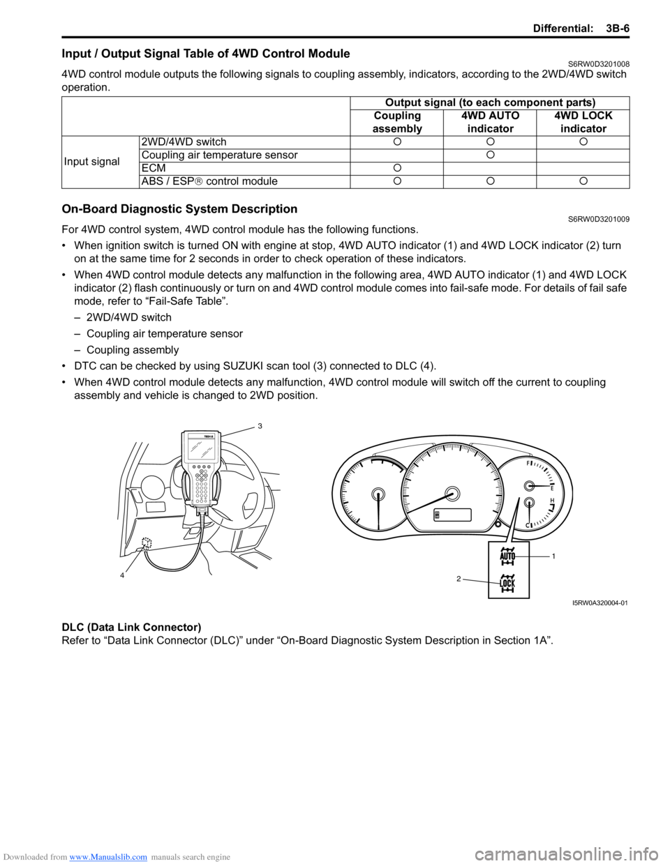
For 4WD control system, 4WD control module has the following functions.
• When ignition switch is turned ON with engine at stop, 4WD AUTO indicator (1) and 4WD LOCK indicator (2) turn
on at the same time for 2 seconds in order to check operation of these indicators.
• When 4WD control module detects any malfunction in the following area, 4WD AUTO indicator (1) and 4WD LOCK
indicator (2) flash continuously or turn on and 4WD control module comes into fail-safe mode. For details of fail safe
mode, refer to “Fail-Safe Table”.
– 2WD/4WD switch
– Coupling air temperature sensor
– Coupling assembly
• DTC can be checked by using SUZUKI scan tool (3) connected to DLC (4).
• When 4WD control module detects any malfunction, 4WD control module will switch off the current to coupling
assembly and vehicle is changed to 2WD position.
DLC (Data Link Connector)
Refer to “Data Link Connector (DLC)” under “On-Board Diagnostic System Description in Section 1A”.Output signal (to each component parts)
Coupling
assembly4WD AUTO
indicator4WD LOCK
indicator
Input signal2WD/4WD switch�{�{�{
Coupling air temperature sensor�{
ECM�{
ABS / ESP® control module�{�{�{
1
2 3
4
I5RW0A320004-01
Page 504 of 1556

Downloaded from www.Manualslib.com manuals search engine 3B-7 Differential:
CAN Communication System DescriptionS6RW0D3201010
Refer to “CAN Communication System Description in Section 1A” for CAN communication system description.
When 4WD control module receive the signal of abnormal as following information, vehicle is not changed to 4WD-
auto and 4WD-lock position.
4WD Control Module Transmission Data
4WD Control Module Reception Data
ECMCombination
Meter
TransmitDATA 4WD
4WD mode status
4WD auto mode
indication status
4WD lock mode
indication status
4WD diagnostic
trouble codes control
module
4WD clutch
engagement percent
ESP® hydraulic unit /
control module
(if equipped)
4WD clutch control
request impossibility
I7RW01320013-01
Accelerator position
Engine speedECM
DATA
Brake pedal switch signal
4WD
control
moduleWheel speed signal
(front right)
Wheel speed signal
(front left)
Wheel speed signal
(rear right)
Wheel speed signal
(rear left)
ABS hydraulic
unit /control
module
(if equipped)
ESP® hydraulic
unit /control
module
(if equipped)
ABS active
ESP® status signal
Clutch control request for
4WD active
Clutch control request
percent
Engine type signal
Engine torque signal
Receive
I7RW01320002-03