Page 511 of 1556

Downloaded from www.Manualslib.com manuals search engine Differential: 3B-14
Rear Differential Symptom DiagnosisS6RW0D3204011
4WD Control Symptom DiagnosisS6RW0D3204012
Diagnose 4WD system after performing the following inspections.
• Perform 4WD control system check referring to “4WD Control System Check”. Condition Possible cause Correction / Reference Item
Gear noiseDeteriorated or water mixed lubricantRepair and replenish referring to “Rear
Differential Oil Change”.
Inadequate or insufficient lubricantRepair and replenish referring to “Rear
Differential Oil Change”.
Maladjusted backlash between drive
bevel pinion and gearAdjust as prescribed referring to “Rear
Differential Disassembly and Reassembly”.
Improper tooth contact in the mesh
between drive bevel pinion and gearAdjust or replace referring to “Rear Differential
Disassembly and Reassembly”.
Loose drive bevel gear securing boltsReplace or retighten referring to “Rear
Differential Disassembly and Reassembly”.
Damaged differential gear(s) or
differential pinion(s)Replace referring to “Rear Differential
Inspection”.
Bearing noise(Constant noise) Deteriorated or water
mixed lubricantRepair and replenish referring to “Rear
Differential Oil Change”.
(Constant noise) Inadequate or
insufficient lubricantRepair and replenish referring to “Rear
Differential Oil Change”.
(Noise while coasting) Damaged
bearing(s) of drive bevel pinionReplace referring to “Rear Differential
Inspection”.
(Noise while turning) Damaged
differential side bearing(s) or axle
bearing(s)Replace referring to “Rear Differential
Inspection”.
Oil leakageClogged breather plugClean.
Worn or damaged oil sealReplace.
Excessive oilAdjust oil level referring to “Rear Differential Oil
Change”.
Loose differential carrier boltsReplace or retighten.
Condition Possible cause Correction / Reference Item
4WD system does not
operate2WD/4WD switch faultyCheck switch referring to “2WD/4WD Switch
Inspection”.
Coupling air temperature sensor faultyCheck coupling air temperature sensor
referring to “Coupling Air Temperature Sensor
Inspection”.
Coupling assembly faultyCheck coupling assembly referring to
“Coupling Assembly Inspection”.
Wiring or grounding faultyRepair as necessary.
4WD control module faultyCheck 4WD control module referring to
“Inspection of 4WD Control Module and Its
Circuits”.
MAF sensor faultyCheck MAF sensor and its circuit.
Accelerator pedal position (APP) sensor
faultyCheck accelerator pedal position (APP) sensor
and its circuit.
CKP sensor faultyCheck CKP sensor and its circuit.
Front and/or rear wheel speed sensor
faultyCheck front and/or rear wheel speed sensor
and its circuit.
Steering angle sensor faultyCheck steering angle sensor and its circuit.
ABS / ESP® control module faultyCheck ABS / ESP
® control module and its
circuit.
ECM faultyCheck ECM and its circuit.
NoiseDamaged or worn bearing(s)Refer to “Rear Differential Inspection”.
Page 1179 of 1556
Downloaded from www.Manualslib.com manuals search engine Wiring Systems: 9A-12
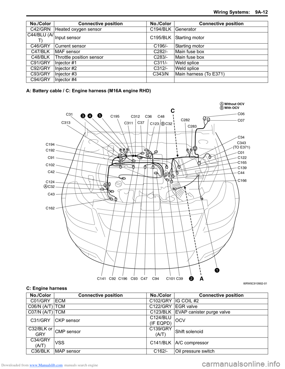
A: Battery cable / C: Engine harness (M16A engine RHD)
C: Engine harnessC42/GRN Heated oxygen sensor C194/BLK Generator
C44/BLU (A/
T)Input sensor C195/BLK Starting motor
C46/GRY Current sensor C196/- Starting motor
C47/BLK MAF sensor C282/- Main fuse box
C48/BLK Throttle position sensor C283/- Main fuse box
C91/GRY Injector #1 C311/- Weld splice
C92/GRY Injector #2 C312/- Weld splice
C93/GRY Injector #3 C343/N Main harness (To E371)
C94/GRY Injector #4 No./Color Connective position No./Color Connective position
C124
C32
C42
C102
C91
C192
C194
C43
C162
C141C196
C195
C93C94C101C39C92
C31
C311C313C312
C36C48
C37C123
C47C32C282
C283
C343
(TO E371)
C01
C34
C07
C06
C122
C165
C139
C44
C166
43
2
1
5C
A
Without OCV
With OCV A
A
B
B
I6RW0C910902-01
No./Color Connective position No./Color Connective position
C01/GRY ECM C102/GRY IG COIL #2
C06/N (A/T) TCM C122/GRY EGR valve
C07/N (A/T) TCM C123/BLK EVAP canister purge valve
C31/GRY CKP sensorC124/BLU
(IF EQPD)OCV
C32/BLK or
GRYCMP sensorC139/GRY
(A/T)Shift solenoid
C34/GRY
(A/T)VSS C141/BLK A/C compressor
C36/BLK MAP sensor C162/- Oil pressure switch
Page 1180 of 1556
Downloaded from www.Manualslib.com manuals search engine 9A-13 Wiring Systems:
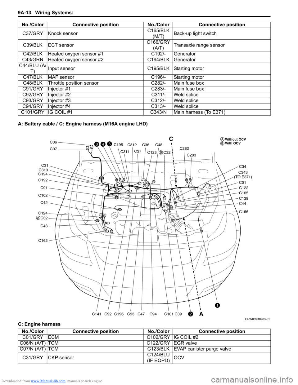
A: Battery cable / C: Engine harness (M16A engine LHD)
C: Engine harnessC37/GRY Knock sensorC165/BLK
(M/T)Back-up light switch
C39/BLK ECT sensorC166/GRY
(A/T)Transaxle range sensor
C42/BLK Heated oxygen sensor #1 C192/- Generator
C43/GRN Heated oxygen sensor #2 C194/BLK Generator
C44/BLU (A/
T)Input sensor C195/BLK Starting motor
C47/BLK MAF sensor C196/- Starting motor
C48/BLK Throttle position sensor C282/- Main fuse box
C91/GRY Injector #1 C283/- Main fuse box
C92/GRY Injector #2 C311/- Weld splice
C93/GRY Injector #3 C312/- Weld splice
C94/GRY Injector #4 C313/- Weld splice
C101/GRY IG COIL #1 C343/N Main harness (To E371)No./Color Connective position No./Color Connective position
C124
C32
C42
C102
C91
C192
C194
C43
C162
C141C196
C195
C93C94C101C39C92
C31
C311
C313C312
C36C48
C37C123
C47C32C282
C283
C343
(TO E371)
C01
C34
C07
C06
C122
C165
C139
C44
C166
43
2
1
5C
AWithout OCV
With OCV A
A
B
B
I6RW0C910903-01
No./Color Connective position No./Color Connective position
C01/GRY ECM C102/GRY IG COIL #2
C06/N (A/T) TCM C122/GRY EGR valve
C07/N (A/T) TCM C123/BLK EVAP canister purge valve
C31/GRY CKP sensorC124/BLU
(IF EQPD)OCV
Page 1181 of 1556
Downloaded from www.Manualslib.com manuals search engine Wiring Systems: 9A-14
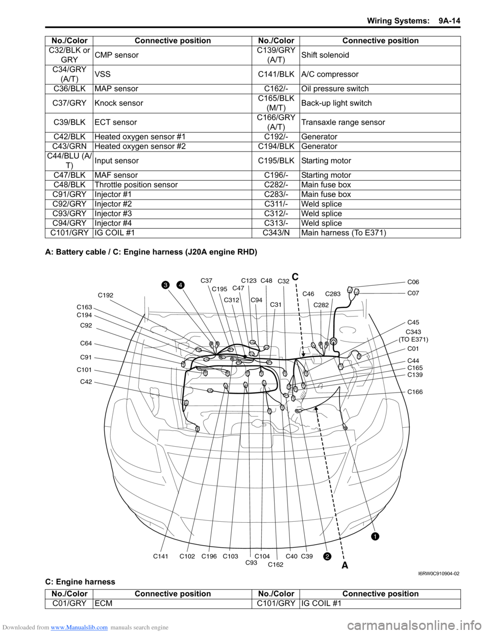
A: Battery cable / C: Engine harness (J20A engine RHD)
C: Engine harnessC32/BLK or
GRYCMP sensorC139/GRY
(A/T)Shift solenoid
C34/GRY
(A/T)VSS C141/BLK A/C compressor
C36/BLK MAP sensor C162/- Oil pressure switch
C37/GRY Knock sensorC165/BLK
(M/T)Back-up light switch
C39/BLK ECT sensorC166/GRY
(A/T)Transaxle range sensor
C42/BLK Heated oxygen sensor #1 C192/- Generator
C43/GRN Heated oxygen sensor #2 C194/BLK Generator
C44/BLU (A/
T)Input sensor C195/BLK Starting motor
C47/BLK MAF sensor C196/- Starting motor
C48/BLK Throttle position sensor C282/- Main fuse box
C91/GRY Injector #1 C283/- Main fuse box
C92/GRY Injector #2 C311/- Weld splice
C93/GRY Injector #3 C312/- Weld splice
C94/GRY Injector #4 C313/- Weld splice
C101/GRY IG COIL #1 C343/N Main harness (To E371)No./Color Connective position No./Color Connective position
C42
C101
C91
C64 C92
C194 C163
C141C102C196 C192
C195
C312
C93C104C103
C94C31C32
C40
C162
C39
C123C48C37
C47
C282
C283C46
C343
(TO E371)
C01
C45
C07
C06
C139 C44
C165
C166
3
2
1
4
A
C
I6RW0C910904-02
No./Color Connective position No./Color Connective position
C01/GRY ECM C101/GRY IG COIL #1
Page 1182 of 1556
Downloaded from www.Manualslib.com manuals search engine 9A-15 Wiring Systems:
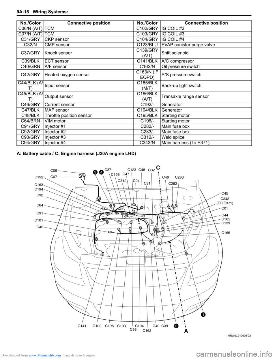
A: Battery cable / C: Engine harness (J20A engine LHD)C06/N (A/T) TCM C102/GRY IG COIL #2
C07/N (A/T) TCM C103/GRY IG COIL #3
C31/GRY CKP sensor C104/GRY IG COIL #4
C32/N CMP sensor C123/BLU EVAP canister purge valve
C37/GRY Knock sensorC139/GRY
(A/T)Shift solenoid
C39/BLK ECT sensor C141/BLK A/C compressor
C40/GRN A/F sensor C162/N Oil pressure switch
C42/GRY Heated oxygen sensorC163/N (IF
EQPD)P/S pressure switch
C44/BLK (A/
T)Input sensorC165/BLK
(M/T)Back-up light switch
C45/BLK (A/
T)Output sensorC166/BLK
(A/T)Transaxle range sensor
C46/GRY Current sensor C192/- Generator
C47/BLK MAF sensor C194/BLK Generator
C48/BLK Throttle position sensor C195/BLK Starting motor
C64/BRN VIM motor C196/- Starting motor
C91/GRY Injector #1 C282/- Main fuse box
C92/GRY Injector #2 C283/- Main fuse box
C93/GRY Injector #3 C312/- Weld splice
C94/GRY Injector #4 C343/N Main harness (To E371) No./Color Connective position No./Color Connective position
C42
C101
C91
C64 C92
C194 C163
C141C102C196 C192
C195
C312
C93C104C103
C94C31C32
C40
C162
C39
C123C48C37
C47
C282
C283C46
C343
(TO E371)
C01
C45
C07
C06
C139 C44
C165
C166
3
2
1
4C
A
I6RW0C910905-02
Page 1183 of 1556
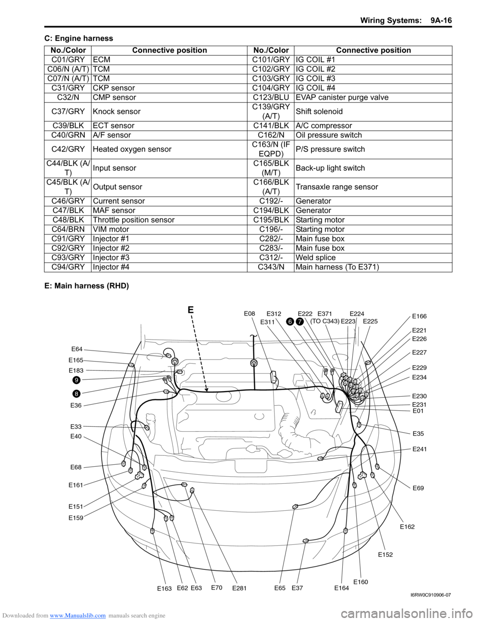
Downloaded from www.Manualslib.com manuals search engine Wiring Systems: 9A-16
C: Engine harness
E: Main harness (RHD)No./Color Connective position No./Color Connective position
C01/GRY ECM C101/GRY IG COIL #1
C06/N (A/T) TCM C102/GRY IG COIL #2
C07/N (A/T) TCM C103/GRY IG COIL #3
C31/GRY CKP sensor C104/GRY IG COIL #4
C32/N CMP sensor C123/BLU EVAP canister purge valve
C37/GRY Knock sensorC139/GRY
(A/T)Shift solenoid
C39/BLK ECT sensor C141/BLK A/C compressor
C40/GRN A/F sensor C162/N Oil pressure switch
C42/GRY Heated oxygen sensorC163/N (IF
EQPD)P/S pressure switch
C44/BLK (A/
T)Input sensorC165/BLK
(M/T)Back-up light switch
C45/BLK (A/
T)Output sensorC166/BLK
(A/T)Transaxle range sensor
C46/GRY Current sensor C192/- Generator
C47/BLK MAF sensor C194/BLK Generator
C48/BLK Throttle position sensor C195/BLK Starting motor
C64/BRN VIM motor C196/- Starting motor
C91/GRY Injector #1 C282/- Main fuse box
C92/GRY Injector #2 C283/- Main fuse box
C93/GRY Injector #3 C312/- Weld splice
C94/GRY Injector #4 C343/N Main harness (To E371)
E68
E40
E33
E165
E36
E161
E151
E159
E70E281E163E62E63E65E37E164
E64
E183
E08
E311
E312E222E224E225E223
E221
E371
(TO C343)E166
E227
E229
E234
E230
E01
E35
E241
E69
E162
E152
E160
E231
E226
8
9
76
E
I6RW0C910906-07
Page 1232 of 1556
Downloaded from www.Manualslib.com manuals search engine 9A-65 Wiring Systems:
2C39
LT GRN
1
C47C01
C01
GRN/ORNGRN/REDBRN/YEL
WHT/RED
C122
3
BLK/REDBLK/REDBLK/REDBLK/RED
55
RED/BLKGRY/RED
GRY/BLU
Weld spliceC311
EGR
valve
4
6312
5
3
4 5 6
MAP
sensor
C363
1
2
C124
ECM
C912
1C922
1C932
1C942
1
#2 #1#3
#4
BLU/REDBLU/WHTBLU/YELBLU/ORN
BLK/RED
BLK/RED
BLU/BLK
EVAP
canister
purge
valve
C123
ECT
sensor
GRY/BLU
GRY/BLUBLK/REDGRYBLU/YELBRN/WHT
"A-4"
Lg
30ARDTR
10
Relay
motor
"A-1"
Generator
BLU/REDLT GRNBRNGRN
BR
BY
46E015017
1
1
2
13 17
16 2
1
242528
26
27
21 4
3
5
LT GRN/BLK
2
57
E371 C343
18
19
OCV
1
2
6059
BLK/REDBLK/REDGRYGRY
BLK/RED
BLK/RED
BLK/RED
4
32
1E226
PNK/BLK
BW
8
GRY/BLU
YEL
Individual circuit
fuse box (No.1)
15ATHR
MOR
3
YEL/BLK
MAF sensor
4
53
1E222
Throttle
motor
relay
M
I6RW0C910936-04
Page 1236 of 1556
Downloaded from www.Manualslib.com manuals search engine 9A-69 Wiring Systems:
2C39
LT GRN
1
C47 C01
C01
C124
ECM
C912
1C922
1C932
1C942
1
#2 #1#3
#4
BLU/REDBLU/WHTBLU/YELBLU/ORN
BLK/RED
BLU/BLKGRN/ORNGRN/REDBRN/YEL
WHT/RED
EVAP
canister
purge
valve
C123 C122
ECT
sensor
GRY/BLU
GRY/BLU
"A-4"
Lg
30ARDTR
10
Relay
motor
"A-1"
Generator
BLU/REDLT GRNBRNGRN
BR
BY
46E014532
1
1
2
29 17
16 2
1
242528
26
27
21 4
3
5
BLK/YEL
2
3
55
E371 C343
18
19
OCV
1
2
6059
BLK/REDBLK/REDGRYGRYBLK/REDBLK/REDBLK/REDBLK/RED
BLK/RED
BLK/RED
BLK/RED
4
32
1E226
GRN/BLK
GRYBLK/REDBLU/YEL
53
RED/BLKGRY/RED
GRY/BLUGRY/BLU
GRN/RED
Individual circuit
fuse box (No.1)
15ATHR
MOR
3
GRN/WHT
MAF sensor
IF EQPD
4
53
1E222
Throttle
motor
relay
M
Weld spliceC311
EGR
valve IF EQPD
IF EQPD
4
6312
5
19
18 4 3
MAP
sensor
C363
1
2
I6RW0D910928-01