Page 1308 of 1556
Downloaded from www.Manualslib.com manuals search engine 9A-141 Wiring Systems:
G-4 Navigation System Circuit DiagramS6RW0D910E059
G2715
5
4
11
2
12
1 5
156
16
"D-4"RY
WHT/RED
WHT/RED
G248
G2481
G307
J/B
15ADOME
37
J/C
BLU/WHT
BLU/WHTRED/YEL
15AACC2
24
Rear (R)
J/C
Rear (L)
GRY/REDGRYLT GRN/BLKLT GRN
GRY/REDGRYLT GRN/BLKLT GRN
GRY/REDGRYLT GRN/BLKLT GRN
1
Navigation
RED/YEL
92
J146
C
CG308
J/C
B
BG306
J/C
D
D
PPLPPL
18G243183
L381
J2175
4L382
J218
J145
G341
L374
G343
L376
1
2
Rear tweeter (R)
GRY/REDGRY
J1511
2
Rear tweeter (L)
LT GRNLT GRN/BLK
J152
A
B
G343
L376
G341
L374A
B
9
6AB8
5AB6
9AB5
8AB
M/T
RED/BLU
RED/BLU
Parking brake
switchBack-up
light switch
"C-3"
RB
"A-8"P
BCM
RED
RED
"D-8"R
E381
G33317
G343
L3763
A/T
Transaxle
range sensor
"D-8"
R
RHD
LHD AB
I6RW0C910A10-02
Page 1324 of 1556
Downloaded from www.Manualslib.com manuals search engine 9B-5 Lighting Systems:
Schematic and Routing Diagram
Headlight Auto Leveling System Wiring Circuit DiagramS6RW0D9202001
G14-12G14-19G14-21
G14-10
G14-23
+B
5V
5V
GRN/YEL
GRY/RED
BLK
G14-112V
BRNLT BLUGRY
RED/BLK
3
G14-13G14-20G14-22
5V
PNKBLUYEL/GRN2
45
9
10 11 1
5V
5V
12V
G14-16
G14-3
PPL
GRN/ORN
5V
G14-5YEL
G14-17GRN
G14-11
G14-24
ORN
WHT6 12VG14-18LT GRN
7
8
G14-6
G14-9
RED/WHT
G14
10 11 12 13 16 17 18 19 205 6 9
21 22 23 24
[A]
I6RW0C920007-01
[A]: Headlight leveling control module connector
(viewed from harness side)4. BCM 8. Headlight leveling warning light
1. Headlight leveling control module 5. Right headlight leveling actuator 9. Ignition switch
2. Front height sensor 6. Left headlight leveling actuator 10. Lighting switch
3. Rear height sensor 7. Combination meter 11. Diagnosis connector
Page 1356 of 1556
Downloaded from www.Manualslib.com manuals search engine 9C-4 Instrumentation / Driver Info. / Horn:
Schematic and Routing Diagram
Combination Meter Circuit DiagramS6RW0D9302001
7
6
5
4G241-99
G241-5
1
2
11
G241-1323
G241-31
G241-263
G241-16
G241-2212
G241-2513
G241-13
8 17
1514
20
G241-32
G241-69
16
18
19
G241-2121
G241-7 G241-10 10
10
G241-1922
I6RW0D930002-01
1. DOME fuse 9. 4WD control module (if equipped) 17. CAN driver
2. METER fuse 10. CAN junction connector 18. Stepper motor and LED output driver
3. Combination switch 11. SDM 19. A/T shift position indicator (“P”, “R”, “N”, “D”, “3”, “2” and “L”)
4. Tachometer 12. Combination switch (high beam) 20. Combination meter
5. Speedometer 13. P/S control module 21. Combination switch (rear fog light)
6. Fuel meter 14. CPU 22. Headlight leveling control module (if equipped)
7. ECT meter 15. Power supply 23. Illumination cancel switch (if equipped)
8. ODO-TRIP 16. Interface circuit
Page 1476 of 1556

Downloaded from www.Manualslib.com manuals search engine 10B-3 Body Electrical Control System:
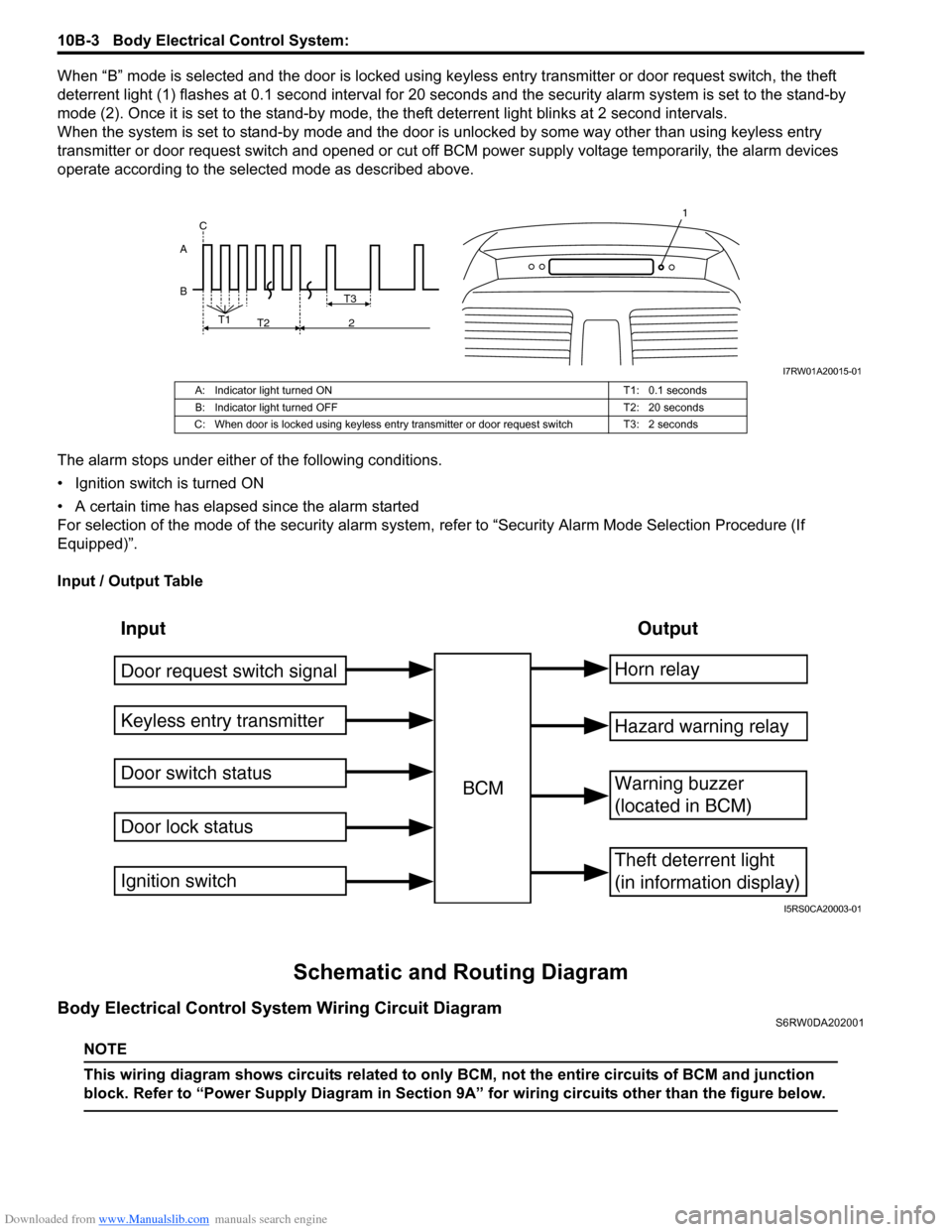
When “B” mode is selected and the door is locked using keyless entry transmitter or door request switch, the theft
deterrent light (1) flashes at 0.1 second interval for 20 seconds and the security alarm system is set to the stand-by
mode (2). Once it is set to the stand-by mode, the theft deterrent light blinks at 2 second intervals.
When the system is set to stand-by mode and the door is unlocked by some way other than using keyless entry
transmitter or door request switch and opened or cut off BCM power supply voltage temporarily, the alarm devices
operate according to the selected mode as described above.
The alarm stops under either of the following conditions.
• Ignition switch is turned ON
• A certain time has elapsed since the alarm started
For selection of the mode of the security alarm system, refer to “Security Alarm Mode Selection Procedure (If
Equipped)”.
Input / Output Table
Schematic and Routing Diagram
Body Electrical Control System Wiring Circuit DiagramS6RW0DA202001
NOTE
This wiring diagram shows circuits related to only BCM, not the entire circuits of BCM and junction
block. Refer to “Power Supply Diagram in Section 9A” for wiring circuits other than the figure below.
B AT3
T1
T2 2 C
1
I7RW01A20015-01
A: Indicator light turned ON T1: 0.1 seconds
B: Indicator light turned OFF T2: 20 seconds
C: When door is locked using keyless entry transmitter or door request switch T3: 2 seconds
Input Output
Keyless entry transmitter
Door switch status
Door lock statusBCMHorn relay
Theft deterrent light
(in information display)
Warning buzzer
(located in BCM)
Hazard warning relay
Door request switch signal
Ignition switch
I5RS0CA20003-01
Page 1505 of 1556
Downloaded from www.Manualslib.com manuals search engine Immobilizer Control System: 10C-3
Schematic and Routing Diagram
Immobilizer Control System Wiring Circuit DiagramS6RW0DA302001
NOTE
For more details about power supply circuit, ground wire circuit, and each circuit for ECM, BCM, ABS
control module, keyless start control module and combination meter, refer to “System Circuit Diagram
in Section 9A”.
BLK/WHT
BLK/ORN12V
G17-1
G17-2
12V
5V
12V
12VYEL/RED
YEL/BLK
G17-4
G17-3
5V
BRN
BRN/YEL
BLK/YEL
1 2
22
2 34
251014
15
1 2 3
4 G17
[A]
5
6
G16-20 G16-29 G16-30 G146-3 G146-7 G146-8
WHT/RED
5V
5V
9
G16-18G16-19 E01-13
E01-28
BLU
BLU
RED
WHTE08-12
E08-1E01-18
E01-3
RED
WHTE08-13
E08-2E04-1
E04-2
WHT
RED
G04-1
G04-3
12V
E04-9
G04-5
PPL/WHTL313-3 8
11
12
13
G17-5WHT 76
G17-6WHT/RED
17
REDWHT
REDWHT
G241-10 G241-7
IG1
18
WHT
REDG04-4
G04-2
16 [B]
I6RW0DA30001-02
Page 1529 of 1556

Downloaded from www.Manualslib.com manuals search engine Keyless Start System: 10E-7
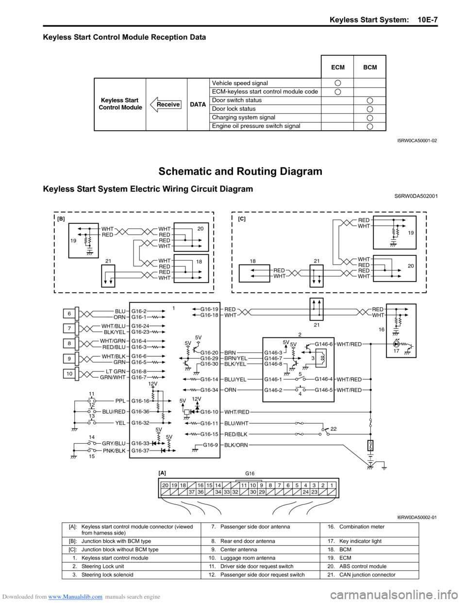
Keyless Start Control Module Reception Data
Schematic and Routing Diagram
Keyless Start System Electric Wiring Circuit DiagramS6RW0DA502001
Vehicle speed signal
ECM-keyless start control module code
Door switch status
Door lock status
Charging system signal
Engine oil pressure switch signalECM BCM
DATA
ReceiveKeyless Start
Control Module
I5RW0CA50001-02
BLK/ORNG16-9
G16-15
G16-14
G16-37G16-33
G16-16
G16-20G16-29G16-30
G16-36
G16-32
G16-10
G16-34
G16-11BLU/WHT
WHT/RED
WHT/RED
PNK/BLKGRY/BLU
BLU/RED
YEL
PPL
RED/BLK
5V5V 5V5V
5V5V
5V12V 12V
G16-2G16-1BLU
ORNWHTREDWHTREDG16-18G16-19
BLU/YEL
ORN
G16-24G16-23
BLK/YEL WHT/BLU
G16-7
GRN/WHTLT GRNG16-8
G16-5G16-6
GRN WHT/BLK
G16-4G16-3 WHT/GRN
RED/BLU
BLK/YELBRN/YELBRNG146-3
G146-1
G146-2G146-5
G146-4
G146-6
G146-7G146-8
WHT/RED
WHT/RED
G16[A]
1 2 3 4 5 6 7 8 9 10 11 14 15 16
36 34 33 32 30 29 24 23 37 18 19 20
WHTRED
WHT
WHT
RED
RED
WHTRED
6
7
8
9
10
11
12
13
14
15118
21
21
2
3
5
419
20
16
17
22
WHTRED
WHTREDWHTRED
18 1920WHTRED
WHTRED
21
[B][C]
I6RW0DA50002-01
[A]: Keyless start control module connector (viewed
from harness side)7. Passenger side door antenna 16. Combination meter
[B]: Junction block with BCM type 8. Rear end door antenna 17. Key indicator light
[C]: Junction block without BCM type 9. Center antenna 18. BCM
1. Keyless start control module 10. Luggage room antenna 19. ECM
2. Steering Lock unit 11. Driver side door request switch 20. ABS control module
3. Steering lock solenoid 12. Passenger side door request switch 21. CAN junction connector