2006 SUZUKI SX4 fog light
[x] Cancel search: fog lightPage 1351 of 1556
Downloaded from www.Manualslib.com manuals search engine Lighting Systems: 9B-32
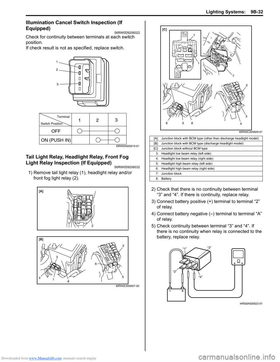
Illumination Cancel Switch Inspection (If
Equipped)
S6RW0D9206022
Check for continuity between terminals at each switch
position.
If check result is not as specified, replace switch.
Tail Light Relay, Headlight Relay, Front Fog
Light Relay Inspection (If Equipped)
S6RW0D9206032
1) Remove tail light relay (1), headlight relay and/or
front fog light relay (2).
2) Check that there is no continuity between terminal
“3” and “4”. If there is continuity, replace relay.
3) Connect battery positive (+) terminal to terminal “2”
of relay.
4) Connect battery negative (–) terminal to terminal “A”
of relay.
5) Check continuity between terminal “3” and “4”. If
there is no continuity when relay is connected to the
battery, replace relay.
1
2
3
Switch PositionTerminal
ON (PUSH IN)123
OFF
I5RW0A920015-01
8
[B] [A]
3
4
1
5 62
2
I6RW0C920027-02
[A]: Junction block with BCM type (other than discharge headlight model)
[B]: Junction block with BCM type (discharge headlight model)
[C]: Junction block without BCM type
3. Headlight low beam relay (left side)
4. Headlight low beam relay (right side)
5. Headlight high beam relay (left side)
6. Headlight high beam relay (right side)
7. Junction block
8. Battery
7
7
5 6
1
8
3
42 [C]
I6RW0C920028-01
“4” “2”“1”“3”
I4RS0A920022-01
Page 1353 of 1556
Downloaded from www.Manualslib.com manuals search engine Instrumentation / Driver Info. / Horn: 9C-1
Body, Cab and Accessories
Instrumentation / Driver Info. / Horn
Precautions
Precautions in Diagnosing Troubles for Combination MeterS6RW0D9300001
Combination meter uses signals (information) from each control module by CAN communication to control
speedometer, tachometer, fuel meter, engine coolant temp meter, warning light and indicator light (other than air bag
warning light, EPS warning light, headlight leveling warning light (if equipped), rear fog light indicator light (if
equipped), high beam indicator light and turn signal indicator light). Therefor, check that no DTC is detected in each
module before performing combination meter symptom diagnosis. If any DTC is detected, correct trouble indicated by
that DTC troubleshooting first.
General Description
CAN Communication System DescriptionS6RW0D9301001
Refer to “CAN Communication System Description in Section 1A” for CAN communication system description.
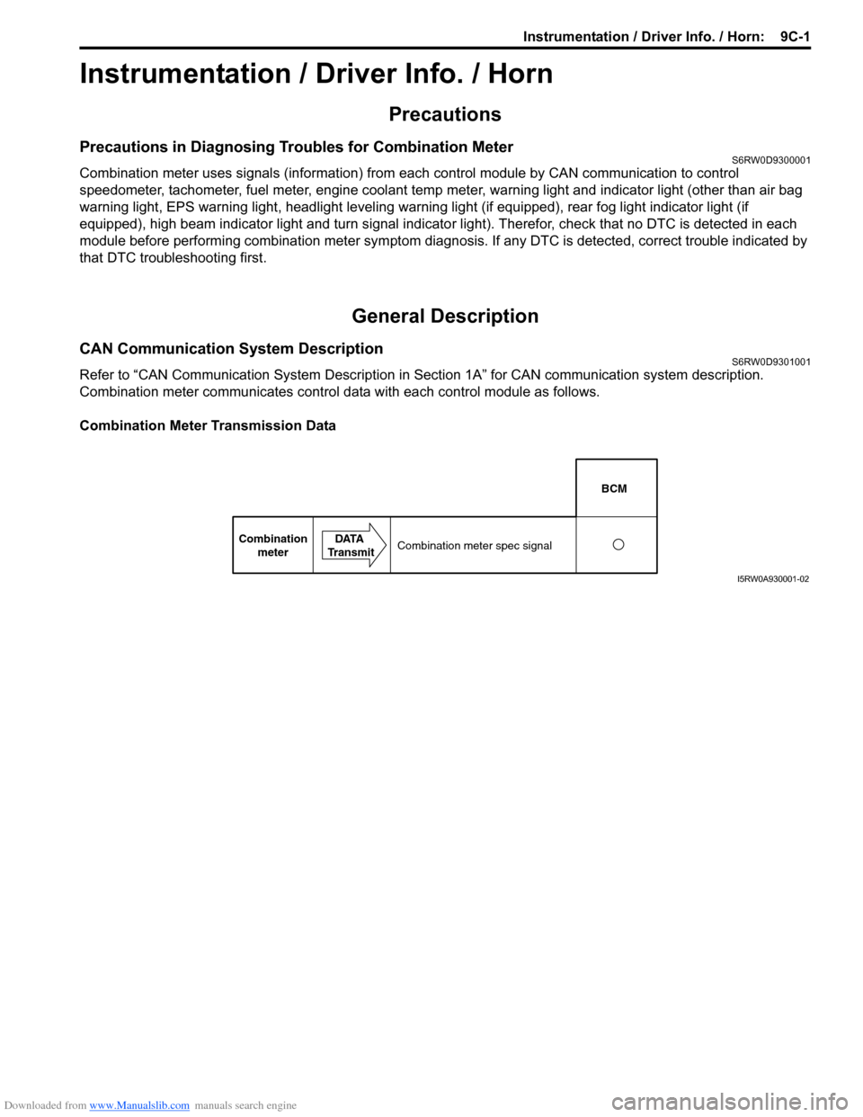
Combination meter communicates control data with each control module as follows.
Combination Meter Transmission Data
BCM
Combination
meterDATA
TransmitCombination meter spec signal
I5RW0A930001-02
Page 1356 of 1556
Downloaded from www.Manualslib.com manuals search engine 9C-4 Instrumentation / Driver Info. / Horn:
Schematic and Routing Diagram
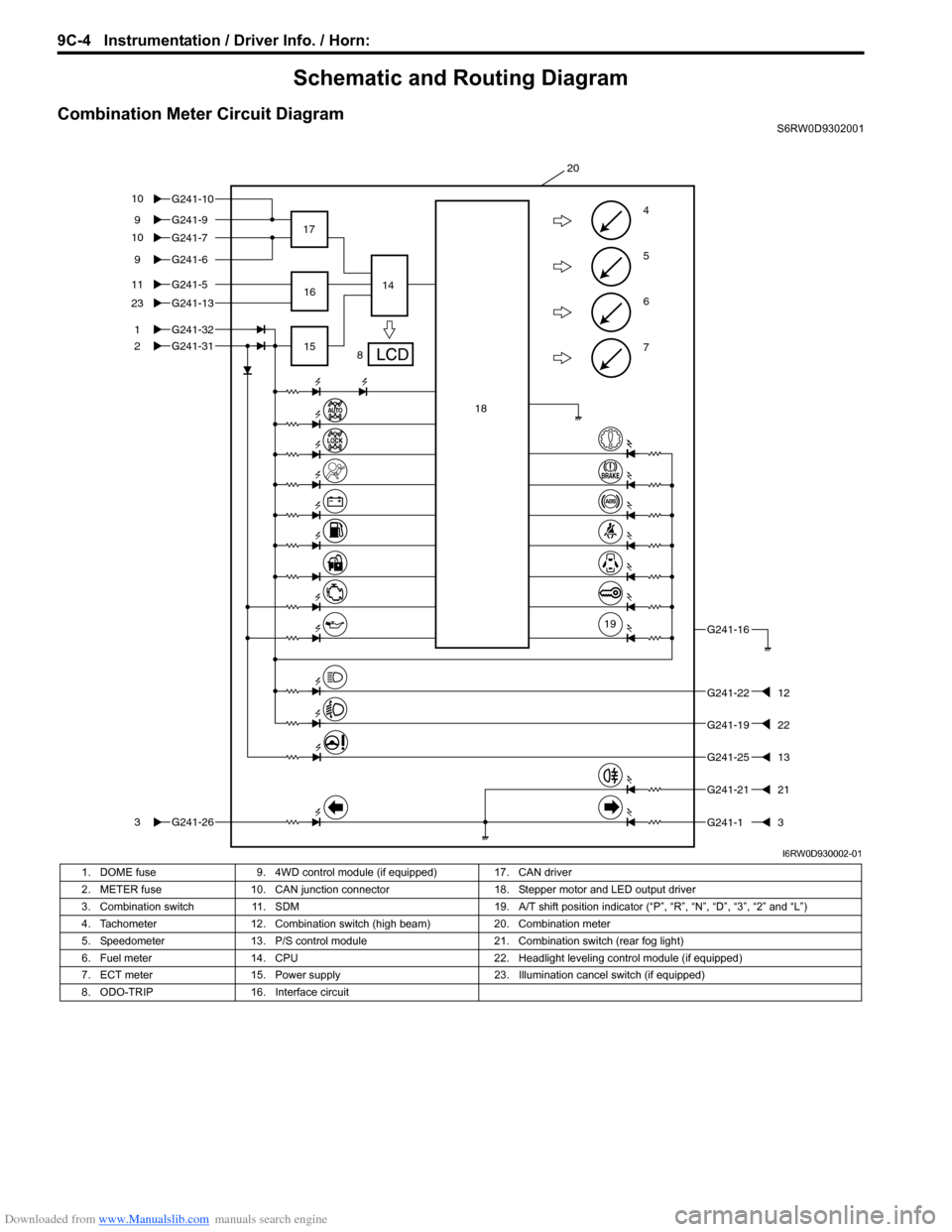
Combination Meter Circuit DiagramS6RW0D9302001
7
6
5
4G241-99
G241-5
1
2
11
G241-1323
G241-31
G241-263
G241-16
G241-2212
G241-2513
G241-13
8 17
1514
20
G241-32
G241-69
16
18
19
G241-2121
G241-7 G241-10 10
10
G241-1922
I6RW0D930002-01
1. DOME fuse 9. 4WD control module (if equipped) 17. CAN driver
2. METER fuse 10. CAN junction connector 18. Stepper motor and LED output driver
3. Combination switch 11. SDM 19. A/T shift position indicator (“P”, “R”, “N”, “D”, “3”, “2” and “L”)
4. Tachometer 12. Combination switch (high beam) 20. Combination meter
5. Speedometer 13. P/S control module 21. Combination switch (rear fog light)
6. Fuel meter 14. CPU 22. Headlight leveling control module (if equipped)
7. ECT meter 15. Power supply 23. Illumination cancel switch (if equipped)
8. ODO-TRIP 16. Interface circuit
Page 1357 of 1556
Downloaded from www.Manualslib.com manuals search engine Instrumentation / Driver Info. / Horn: 9C-5
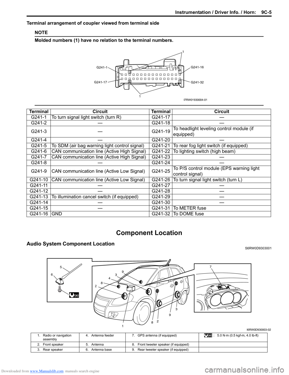
Terminal arrangement of coupler viewed from terminal side
NOTE
Molded numbers (1) have no relation to the terminal numbers.
Component Location
Audio System Component LocationS6RW0D9303001
Terminal Circuit Terminal Circuit
G241-1 To turn signal light switch (turn R) G241-17 —
G241-2 — G241-18 —
G241-3 — G241-19To headlight leveling control module (if
equipped)
G241-4 — G241-20 —
G241-5 To SDM (air bag warning light control signal) G241-21 To rear fog light switch (if equipped)
G241-6 CAN communication line (Active High Signal) G241-22 To lighting switch (high beam)
G241-7 CAN communication line (Active High Signal) G241-23 —
G241-8 — G241-24 —
G241-9 CAN communication line (Active Low Signal) G241-25To P/S control module (EPS warning light
control signal)
G241-10 CAN communication line (Active Low Signal) G241-26 To turn signal light switch (turn L)
G241-11 — G241-27 —
G241-12 — G241-28 —
G241-13 To illumination cancel switch (if equipped) G241-29 —
G241-14 — G241-30 —
G241-15 — G241-31 To METER fuse
G241-16 GND G241-32 To DOME fuse
G241-1G241-16
G241-32 G241-17
11I7RW01930004-01
3
2
3
2
1
4
8
8
9
96
5
(a)
7
I6RW0D930003-02
1. Radio or navigation
assembly4. Antenna feeder 7. GPS antenna (if equipped) : 5.0 N⋅m (0.5 kgf-m, 4.0 lb-ft)
2. Front speaker 5. Antenna 8. Front tweeter speaker (if equipped)
3. Rear speaker 6. Antenna base 9. Rear tweeter speaker (if equipped)
Page 1382 of 1556
Downloaded from www.Manualslib.com manuals search engine 9D-8 Wipers / Washers:
Windshield Wiper and Washer Switch Removal
and Installation
S6RW0D9406008
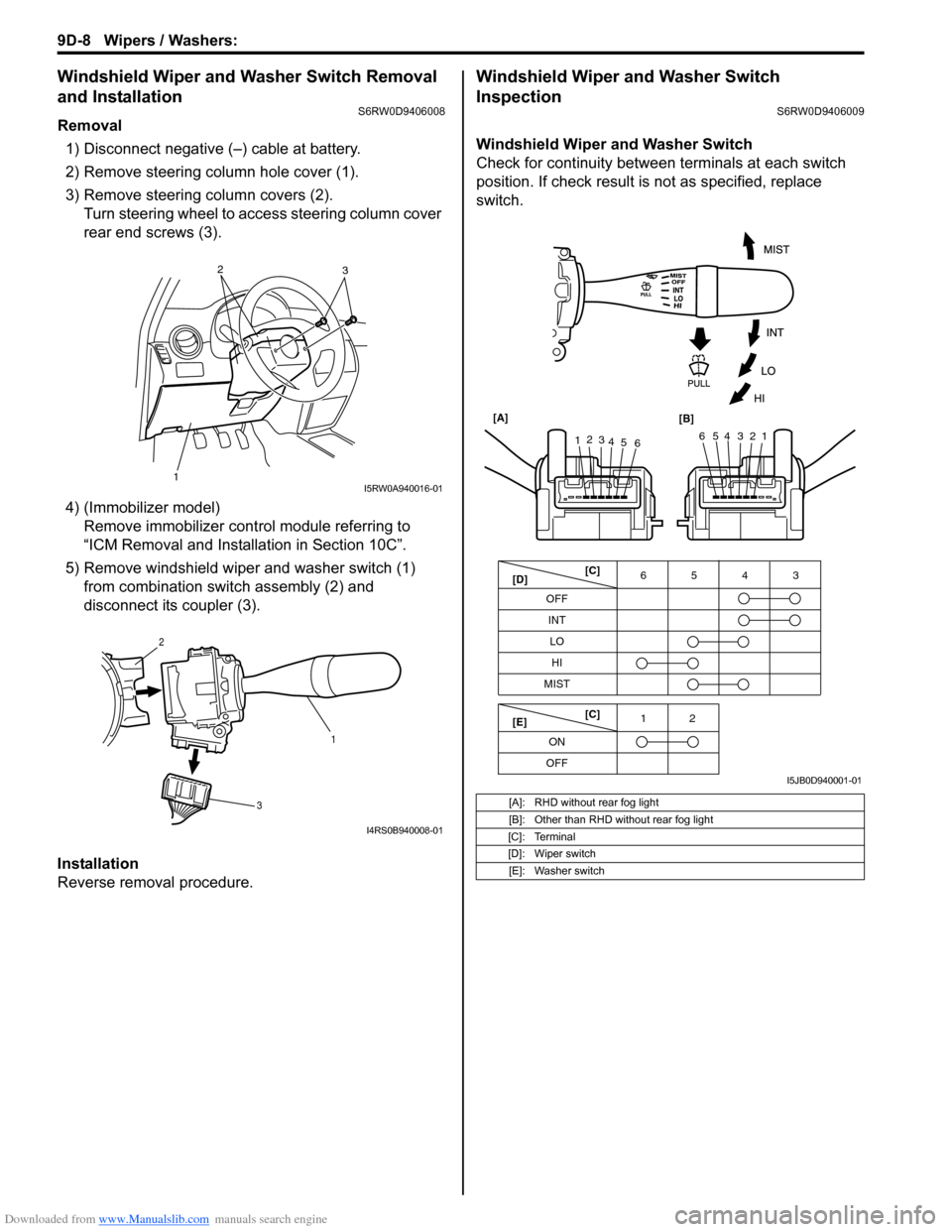
Removal
1) Disconnect negative (–) cable at battery.
2) Remove steering column hole cover (1).
3) Remove steering column covers (2).
Turn steering wheel to access steering column cover
rear end screws (3).
4) (Immobilizer model)
Remove immobilizer control module referring to
“ICM Removal and Installation in Section 10C”.
5) Remove windshield wiper and washer switch (1)
from combination switch assembly (2) and
disconnect its coupler (3).
Installation
Reverse removal procedure.
Windshield Wiper and Washer Switch
Inspection
S6RW0D9406009
Windshield Wiper and Washer Switch
Check for continuity between terminals at each switch
position. If check result is not as specified, replace
switch.
12
3I5RW0A940016-01
1 2
3
I4RS0B940008-01
[A]: RHD without rear fog light
[B]: Other than RHD without rear fog light
[C]: Terminal
[D]: Wiper switch
[E]: Washer switch
OFF
INT6543
MIST
OFF12
ONLO
HI
65432112
3
4
5
6 [A]
[B]
[C]
[D]
[E][C]
I5JB0D940001-01
Page 1383 of 1556
Downloaded from www.Manualslib.com manuals search engine Wipers / Washers: 9D-9
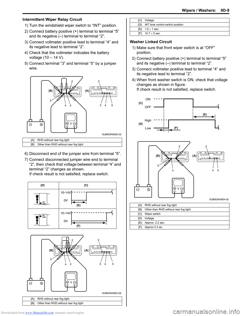
Intermittent Wiper Relay Circuit
1) Turn the windshield wiper switch to “INT” position.
2) Connect battery positive (+) terminal to terminal “5”
and its negative (–) terminal to terminal “2”.
3) Connect voltmeter positive lead to terminal “4” and
its negative lead to terminal “2”.
4) Check that the voltmeter indicates the battery
voltage (10 – 14 V).
5) Connect terminal “3” and terminal “5” by a jumper
wire.
6) Disconnect end of the jumper wire from terminal “5”.
7) Connect disconnected jumper wire end to terminal
“2”, then check that voltage between terminal “4” and
terminal “2” changes as shown.
If check result is not satisfied, replace switch.Washer Linked Circuit
1) Make sure that front wiper switch is at “OFF”
position.
2) Connect battery positive (+) terminal to terminal “5”
and its negative (–) terminal to terminal “2”.
3) Connect voltmeter positive lead to terminal “4” and
its negative lead to terminal “2”.
4) When front washer switch is ON, check that voltage
changes as shown in figure.
If check result is not satisfied, replace switch.
[A]: RHD without rear fog light
[B]: Other than RHD without rear fog light
[A]: RHD without rear fog light
[B]: Other than RHD without rear fog light
V
2
3 4 52
34 5 [B] [A]
I5JB0D940002-02
V
INT
TIME
INT
TIME
10-14V
0V
10-14V
0V
2
3 4 52
34 5 [B] [A][C] [D]
[E]
[F]
I5JB0D940003-02
[C]: Voltage
[D]: INT time control switch position
[E]: 1.6 ± 1 sec.
[F]: 10.7 ± 5 sec.
[A]: RHD without rear fog light
[B]: Other than RHD without rear fog light
[C]: Wiper switch
[D]: Voltage
[E]: Approx. 2.2 sec.
[F]: Approx 0.3 se.
V
2
4 52
45 [B] [A]
ON
OFF
High
Low
[E]
[F] [C]
[D]
I5JB0D940004-02
Page 1384 of 1556
Downloaded from www.Manualslib.com manuals search engine 9D-10 Wipers / Washers:
Rear Wiper and Washer Switch Removal and
Installation
S6RW0D9406010
For removal and installation, refer to “Windshield Wiper
and Washer Switch Removal and Installation”.
Rear Wiper and Washer Switch InspectionS6RW0D9406011
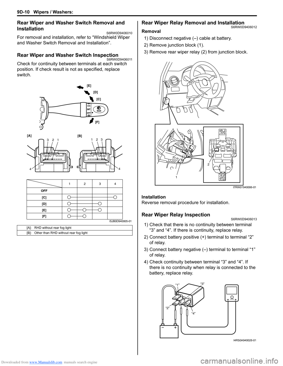
Check for continuity between terminals at each switch
position. If check result is not as specified, replace
switch.
Rear Wiper Relay Removal and InstallationS6RW0D9406012
Removal
1) Disconnect negative (–) cable at battery.
2) Remove junction block (1).
3) Remove rear wiper relay (2) from junction block.
Installation
Reverse removal procedure for installation.
Rear Wiper Relay InspectionS6RW0D9406013
1) Check that there is no continuity between terminal
“3” and “4”. If there is continuity, replace relay.
2) Connect battery positive (+) terminal to terminal “2”
of relay.
3) Connect battery negative (–) terminal to terminal “1”
of relay.
4) Check continuity between terminal “3” and “4”. If
there is no continuity when relay is connected to the
battery, replace relay.[A]: RHD without rear fog light
[B]: Other than RHD without rear fog light
OFF
[C]
[D]4 3 12
1 2 3
4 [A]
[B]123
4 [C] [D] [E]
[F]
[E]
[F]
I5JB0D940005-01
2
1
I7RW01940006-01
“4” “2”“1”“3”
I4RS0A940028-01
Page 1474 of 1556
Downloaded from www.Manualslib.com manuals search engine 10B-1 Body Electrical Control System:
Control Systems
Body Electrical Control System
Precautions
Precautions in Diagnosing TroubleS6RW0DA200001
• Diagnostic information stored in BCM memory can be cleared as well as checked by using SUZUKI scan tool.
Before using scan tool, read its Operator’s (Instruction) Manual carefully to have good understanding as to what
functions are available and how to use it.
• Be sure to read “Precautions for Electrical Circuit Service in Section 00” before inspection and observe what is
written there.
• Communication of ECM, TCM (A/T model), ABS control module, 4WD control module (if equipped), keyless start
control module (if equipped), combination meter and BCM is established by CAN (Controller Area Network). For
detail of CAN communication for BCM, refer to “CAN Communication System Description”. Therefore, handle CAN
communication line with care referring to “Precaution for CAN Communication System in Section 00”.
General Description
BCM General DescriptionS6RW0DA201001
The Body electrical Control Module (BCM) is
incorporated in junction block. Do not attempt removal of
BCM from junction block as it may cause contact failure.
The BCM incorporates relays and controllers which are
used for the following systems and controls them.
• Power door lock (if equipped)
• Keyless entry (if equipped)
• Door lock function of keyless start system (if
equipped)
• Rear wiper
• Combination meter
• Interior light• Warning buzzer
• Rear end door window defogger and door mirror
heater (if equipped)
• Rear end door opener (if equipped)
• Theft deterrent light
Also, the BCM has a function to cause the interior light
and open door warning light in the combination meter to
turn off when any door is left open for longer than 15
minutes to reduce wasteful battery consumption.
In addition, it is possible to check operation of actuator
which is controlled by BCM by using the output test
function of SUZUKI scan tool to operate actuator
simulatively.
CAN Communication System DescriptionS6RW0DA201002
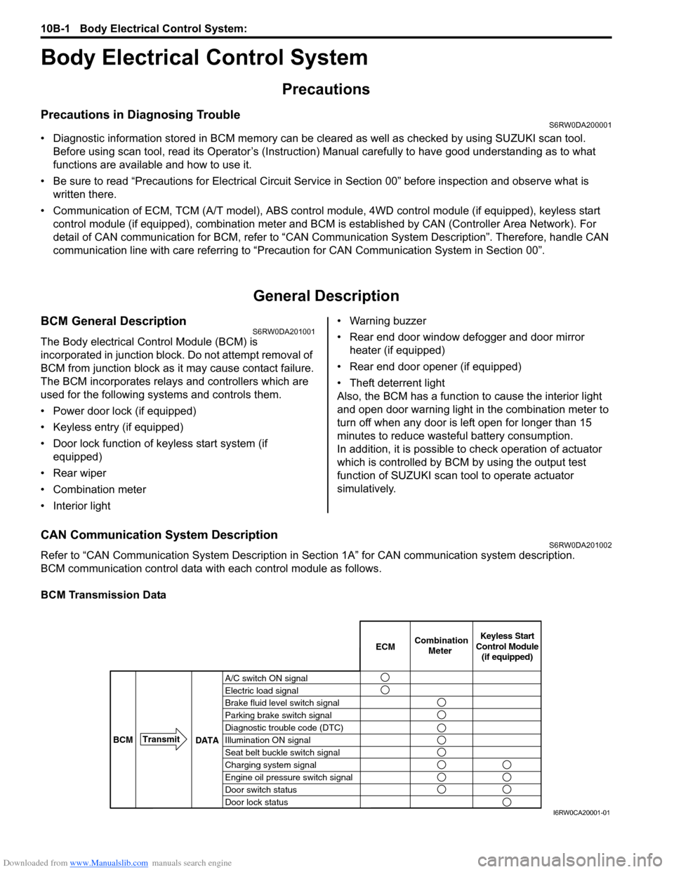
Refer to “CAN Communication System Description in Section 1A” for CAN communication system description.
BCM communication control data with each control module as follows.
BCM Transmission Data
A/C switch ON signal
Electric load signal
Brake fluid level switch signal
Parking brake switch signal
Diagnostic trouble code (DTC)
Illumination ON signal
Seat belt buckle switch signal
Charging system signal
Engine oil pressure switch signal
Door switch status
Door lock statusECMKeyless Start
Control Module
(if equipped) Combination
Meter
BCMTransmit
DATA
I6RW0CA20001-01