Page 1204 of 1556

Downloaded from www.Manualslib.com manuals search engine 9A-37 Wiring Systems:
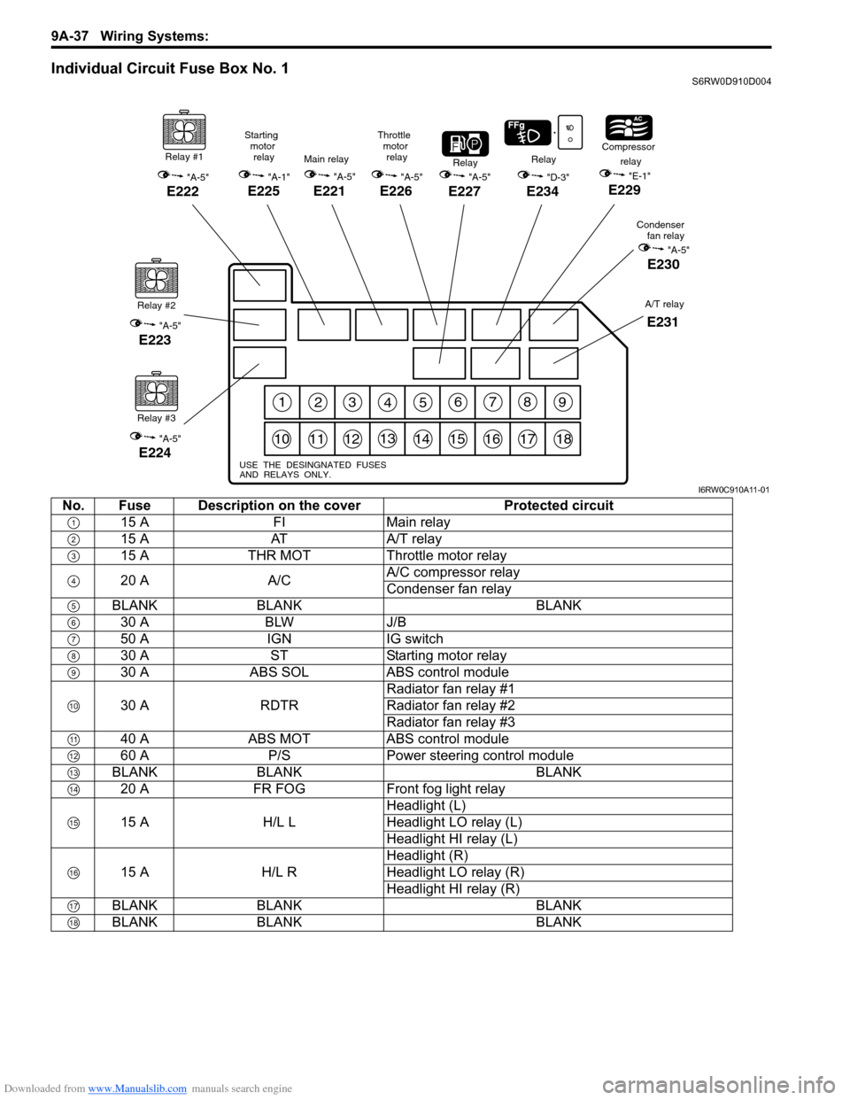
Individual Circuit Fuse Box No. 1S6RW0D910D004
123456789
101112131415161718
USE THE DESINGNATED FUSES
AND RELAYS ONLY.
Relay #1
"A-5"
E222
Relay #2
"A-5"
E223
Relay #3
"A-5"
E224
"A-5"
E227
RelayRelay
"D-3"
E234
Compressor
relay
"E-1"
E229
Condenser
fan relay
"A-5"
E230
Main relay
"A-5"
E221
Starting
motor
relay
"A-1"
E225
Throttle
motor
relay
"A-5"
E226
A/T relay
E231
I6RW0C910A11-01
No. Fuse Description on the cover Protected circuit
15 A FI Main relay
15 A AT A/T relay
15 A THR MOT Throttle motor relay
20 A A/CA/C compressor relay
Condenser fan relay
BLANK BLANK BLANK
30 A BLW J/B
50 A IGN IG switch
30 A ST Starting motor relay
30 A ABS SOL ABS control module
30 A RDTRRadiator fan relay #1
Radiator fan relay #2
Radiator fan relay #3
40 A ABS MOT ABS control module
60 A P/S Power steering control module
BLANK BLANK BLANK
20 A FR FOG Front fog light relay
15 A H/L LHeadlight (L)
Headlight LO relay (L)
Headlight HI relay (L)
15 A H/L RHeadlight (R)
Headlight LO relay (R)
Headlight HI relay (R)
BLANK BLANK BLANK
BLANK BLANK BLANK
Page 1206 of 1556

Downloaded from www.Manualslib.com manuals search engine 9A-39 Wiring Systems:
30 A WIPCOMB switch
Windshield washer motor
Windshield wiper motor
Rear wiper relay
DRL controller
10 A IG1 SIGPower steering control module
A/T relay
Brake light switch
15 A A/B A/B SDM
10 A ABSABS control module
G sensor
10 A TAILCOMB switch
DRL controller
15 A STOP Brake light switch
20 A D/L BCM
15 A 4WD 4WD control module
10 A ST SIG Starting motor relay
15 A S/HSeat heater switch (Driver side)
Seat heater switch (Passenger side)
10 A IG2 SIG Blower fan relay
15 A RR FOG COMB switch
15 A DOMEAudio
BCM
COMB meter
DLC
ECM
Interior light
ICM
TCM
Rear interior light
Luggage compartment light
Main switch (Key switch)
Multi information display
KLS ECM
30 A RR DEFRear defogger relay
Mirror motor (R)
Mirror motor (L)
15 A HORN-HAZHorn relay
Flasher relay
BLANK BLANK BLANK
BLANK BLANK BLANK
30 A P/WPower window main switch
Front power window sub switch
Rear power window sub switch (R)
Rear power window sub switch (L) No. Fuse Description on the cover Protected circuit
Page 1208 of 1556
Downloaded from www.Manualslib.com manuals search engine 9A-41 Wiring Systems:
10 A ABSABS control module
G sensor
BLANK BLANK BLANK
15 A STOP Brake light switch
20 A D/L BCM
BLANK BLANK BLANK
10 A ST SIG Starting motor relay
BLANK BLANK BLANK
10 A IG2 SIG Blower fan relay
10 A TAIL Tail light relay
15 A DOMEAudio
BCM
COMB meter
DLC
ECM
Interior light
ICM
TCM
Rear interior light
Luggage compartment light
Main switch (Key switch)
Multi information display
KLS ECM
30 A RR DEFRear defogger relay
Mirror motor (R)
Mirror motor (L)
15 A HORN-HAZHorn relay
Flasher relay
BLANK BLANK BLANK
BLANK BLANK BLANK
30 A P/WPower window main switch
Front power window sub switch
Rear power window sub switch (R)
Rear power window sub switch (L) No. Fuse Description on the cover Protected circuit
Page 1224 of 1556

Downloaded from www.Manualslib.com manuals search engine 9A-57 Wiring Systems:
System Circuit Diagram
System Circuit DiagramS6RW0D910E001
Refer to “A-1 Cranking System Circuit Diagram”.
Refer to “A-2 Charging System Circuit Diagram”.
Refer to “A-3 Ignition System Circuit Diagram (M15A engine, M16A engine)”.
Refer to “A-3 Ignition System Circuit Diagram (J20A engine)”.
Refer to “A-4 Cooling System Circuit Diagram (M15A engine, M16A engine)”.
Refer to “A-4 Cooling System Circuit Diagram (J20A engine)”.
Refer to “A-5 Engine and A/C Control System Circuit Diagram (M15A engine)”.
Refer to “A-5 Engine and A/C Control System Circuit Diagram (M16A engine)”.
Refer to “A-5 Engine and A/C Control System Circuit Diagram (J20A engine)”.
Refer to “A-6 A/T Control System Circuit Diagram”.
Refer to “A-7 Immobilizer System Circuit Diagram”.
Refer to “A-8 Body Control System Circuit Diagram (Except Taiwan)”.
Refer to “A-8 Body Control System Circuit Diagram (Taiwan)”.
Refer to “A-10 4WD Control System (Except Taiwan)”
Refer to “B-1 Windshield Wiper and Washer Circuit Diagram”.
Refer to “B-2 Rear Wiper and Washer Circuit Diagram (Except Taiwan)”.
Refer to “B-2 Rear Wiper and Washer Circuit Diagram (Taiwan)”.
Refer to “B-3 Rear Defogger Circuit Diagram (Except Taiwan)”.
Refer to “B-3 Rear Defogger Circuit Diagram (Taiwan)”.
Refer to “B-4 Power Window Circuit Diagram”.
Refer to “B-5 Power Door Lock Circuit Diagram (Except Taiwan)”.
Refer to “B-5 Power Door Lock Circuit Diagram (Taiwan)”.
Refer to “B-6 Power Mirror Circuit Diagram (Except Taiwan)”.
Refer to “B-6 Power Mirror Circuit Diagram (Taiwan)”.
Refer to “B-7 Horn Circuit Diagram”.
Refer to “B-8 Seat Heater Circuit Diagram”.
Refer to “B-9 Keyless Start System Circuit Diagram”
Refer to “C-1 Combination Meter Circuit Diagram (Meter)”.
Refer to “C-2 Combination Meter Circuit Diagram (Indicator)”.
Refer to “C-3 Combination Meter Circuit Diagram (Warning Light)”.
Refer to “D-1 Headlight System Circuit Diagram (Except Taiwan)”.
Refer to “D-1 Headlight System Circuit Diagram (Taiwan)”.
Refer to “D-2 Position, Tail and Licence Plate Light System Circuit Diagram (Except Taiwan)”.
Refer to “D-2 Position, Tail and Licence Plate Light System Circuit Diagram (Taiwan)”.
Refer to “D-3 Front Fog Light System Circuit Diagram (Except Taiwan)”.
Refer to “D-3 Front Fog Light System Circuit Diagram (Taiwan)”.
Refer to “D-4 Illumination Light System Circuit Diagram (Except Taiwan)”.
Refer to “D-4 Illumination Light System Circuit Diagram (Taiwan)”.
Refer to “D-5 Interior Light System Circuit Diagram (Except Taiwan)”.
Refer to “D-5 Interior Light System Circuit Diagram (Taiwan)”.
Refer to “D-6 Turn Signal and Hazard Warning Light System Circuit Diagram (Except Taiwan)”.
Refer to “D-6 Turn Signal and Hazard Warning Light System Circuit Diagram (Taiwan)”.
Refer to “D-7 Brake Light System Circuit Diagram”.
Refer to “D-8 Back-Up Light System Circuit Diagram”.
Refer to “D-9 Headlight Beam Leveling System Circuit Diagram (Manual Leveling)”.
Refer to “D-10 Rear Fog Light Circuit Diagram”.
Refer to “E-1 Heater System Circuit Diagram”.
Refer to “E-2 Auto A/C System Circuit Diagram”.
Refer to “F-1 Air-Bag System Circuit Diagram (4ch)”.
Refer to “F-1 Air-Bag System Circuit Diagram (8ch)”.
Refer to “F-2 Anti-Lock Brake System Circuit Diagram”.
Refer to “F-4 Power Steering System Circuit Diagram”.
Refer to “G-1 Audio System Circuit Diagram”.
Refer to “G-2 Multi Information Display / Accessory Socket System Circuit Diagram”.
Refer to “G-4 Navigation System Circuit Diagram”.
Page 1280 of 1556
Downloaded from www.Manualslib.com manuals search engine 9A-113 Wiring Systems:
D-3 Front Fog Light System Circuit Diagram (Except Taiwan)S6RW0D910E052
FR
FOG
(R) (L)
2
E1641
2
E1631
20A
14
Relay
Switch
3
E2342
14
WHT/GRNGRY/RED
LT GRN
BLK
BLKBLK
LT GRNLT GRN
1
D
DG334
E382
FREEIG LOAD E Il Ile
TERMINAL
POSITION
PUSH
6 7
4
8
G306
G151
RED/YEL
RED/YELGRY/REDRED/YEL
RED/YEL
11
BLK
BLK
RED/BLU
RED/BLU
5
J/C
B
BG309
J/C
A
A
C
CG306
J/C
BLK
BLK
RY"D-4"
BLKBLK
BLK
14
Individual circuit
fuse box (No.1)
9
BLK
7I6RW0C910983-01
Page 1281 of 1556
Downloaded from www.Manualslib.com manuals search engine Wiring Systems: 9A-114
D-3 Front Fog Light System Circuit Diagram (Taiwan)S6RW0D910E024
FR
FOG
(R) (L)
2
E1641
2
E1631
20A
14
Relay
Switch
3
E2342
14
WHT/GRNRED/YEL
RED/YEL
LT GRN
BLK
BLKBLK
LT GRNLT GRN
14
D
DG333
E381
13E381
G333
FREEIG LOAD E Il Ile
TERMINAL
POSITION
PUSH
7 6
4
8
G306
G151
RED/YEL
RED/YELGRY/REDRED/YEL
RED/YEL
11
BLK/YEL
BLK/YEL
5
J/C
B
BG309
J/C
A
AG306
J/C J/B
BLK
BLK
BLK
BLK
RY"D-4"GR
B
"A-8"
BLKBLK
BLK
14
Individual circuit
fuse box (No.1)
9
BLK
7
BCM
"A-8"
BCM
I6RW0C910982-01
Page 1293 of 1556
Downloaded from www.Manualslib.com manuals search engine Wiring Systems: 9A-126
D-10 Rear Fog Light Circuit DiagramS6RW0D910E061
202123
BLKBLK
BLK
L390
O2312
15ARR
FOG
BLK
YEL/GRN
YEL/GRN
YEL/BLK
OFF
ON
54
"C-1"
YG
YG
G1443
G27210
4
J/B
G343
L3764
36
L133
L134B
A
A
B
Switch
(COMB switch)RHD
LHD A
B
I6RW0D910922-03
Page 1326 of 1556

Downloaded from www.Manualslib.com manuals search engine 9B-7 Lighting Systems:
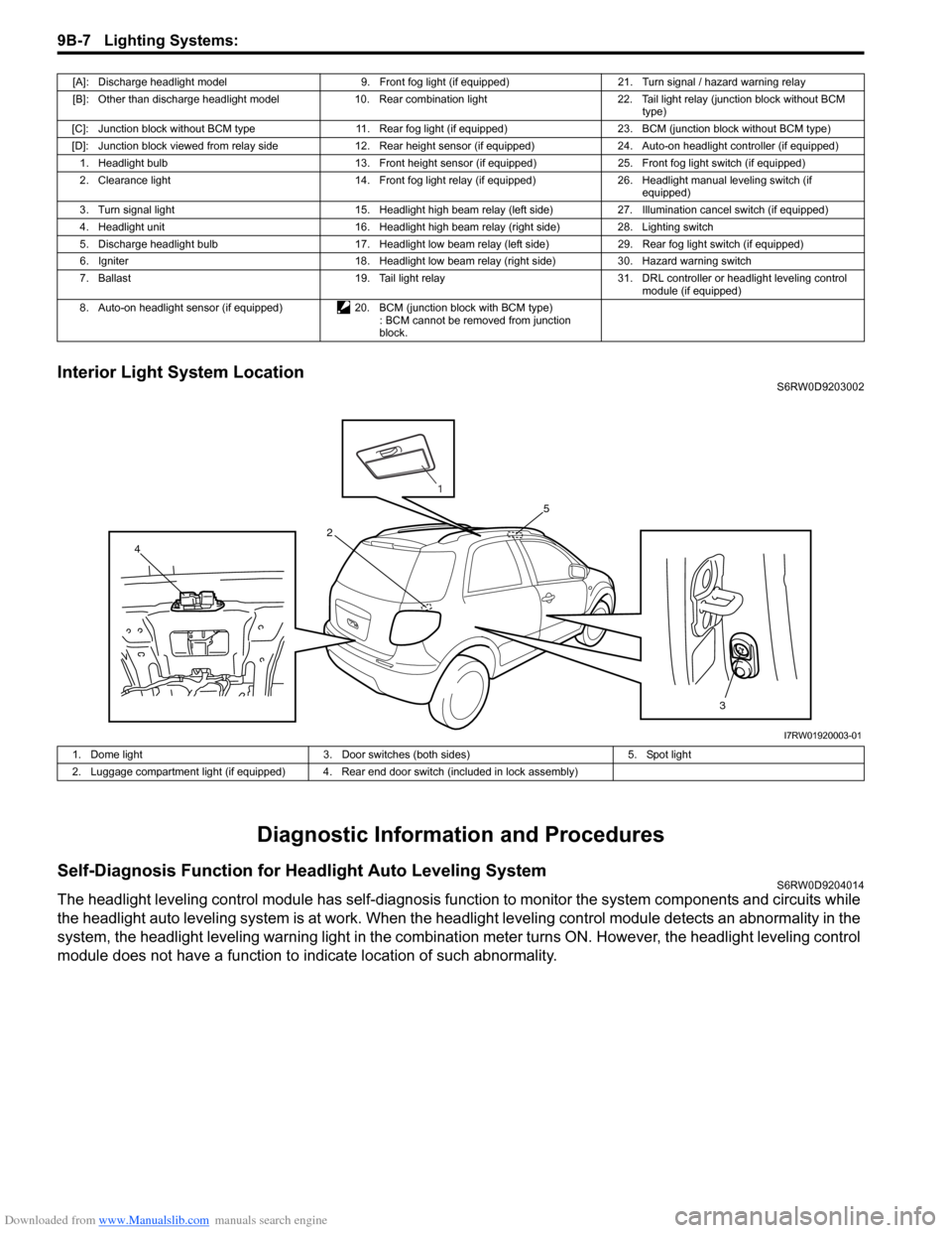
Interior Light System LocationS6RW0D9203002
Diagnostic Information and Procedures
Self-Diagnosis Function for Headlight Auto Leveling SystemS6RW0D9204014
The headlight leveling control module has self-diagnosis function to monitor the system components and circuits while
the headlight auto leveling system is at work. When the headlight leveling control module detects an abnormality in the
system, the headlight leveling warning light in the combination meter turns ON. However, the headlight leveling control
module does not have a function to indicate location of such abnormality.
[A]: Discharge headlight model 9. Front fog light (if equipped) 21. Turn signal / hazard warning relay
[B]: Other than discharge headlight model 10. Rear combination light 22. Tail light relay (junction block without BCM
type)
[C]: Junction block without BCM type 11. Rear fog light (if equipped) 23. BCM (junction block without BCM type)
[D]: Junction block viewed from relay side 12. Rear height sensor (if equipped) 24. Auto-on headlight controller (if equipped)
1. Headlight bulb 13. Front height sensor (if equipped) 25. Front fog light switch (if equipped)
2. Clearance light 14. Front fog light relay (if equipped) 26. Headlight manual leveling switch (if
equipped)
3. Turn signal light 15. Headlight high beam relay (left side) 27. Illumination cancel switch (if equipped)
4. Headlight unit 16. Headlight high beam relay (right side) 28. Lighting switch
5. Discharge headlight bulb 17. Headlight low beam relay (left side) 29. Rear fog light switch (if equipped)
6. Igniter 18. Headlight low beam relay (right side) 30. Hazard warning switch
7. Ballast 19. Tail light relay 31. DRL controller or headlight leveling control
module (if equipped)
8. Auto-on headlight sensor (if equipped) 20. BCM (junction block with BCM type)
: BCM cannot be removed from junction
block.
3 4
5
2
1
I7RW01920003-01
1. Dome light 3. Door switches (both sides) 5. Spot light
2. Luggage compartment light (if equipped) 4. Rear end door switch (included in lock assembly)