2006 SUZUKI SX4 cylinder block
[x] Cancel search: cylinder blockPage 376 of 1556

Downloaded from www.Manualslib.com manuals search engine 1F-11 Engine Cooling System:
Installation
1) Install belt (1) to water pump pulley (2), crankshaft
pulley (3) and generator pulley (4).
2) Adjust belt tension referring to “Water Pump /
Generator Drive Belt Tension Inspection and
Adjustment”.
3) If vehicle equipped with A/C, install compressor drive
belt referring to “Compressor Drive Belt Removal
and Installation in Section 7B” or “Compressor Drive
Belt Removal and Installation in Section 7B”.
4) Connect negative cable at battery.
Water Pump Removal and InstallationS6RW0D1606016
Removal
1) Disconnect negative cable at battery.
2) Drain coolant.
3) Remove water pump / generator drive belt referring
to “Water Pump / Generator Drive Belt Removal and
Installation”.
4) Remove water pump pulley.
5) Remove water pump assembly (1).Installation
1) Apply sealant to mating surface of water pump (1) as
shown in figure.
“A”: Water tight sealant 99000–31250 (SUZUKI
Bond No.1207F)
Sealant quantity (to mating surface of water
pump)
Width “a”: 3 mm (0.12 in.)
Height “b”: 2 mm (0.08 in.)
2) Install water pump assembly (1) to cylinder block
and tighten bolts and nut to specified torque.
Tightening torque
Water pump bolt and nut (a): 25 N·m (2.5 kgf-m,
18.0 lb-ft)
3) Install water pump pulley.
4) Install water pump / generator drive belt referring to
“Water Pump / Generator Drive Belt Removal and
Installation”.
5) Install A/C compressor belt referring to “Compressor
Drive Belt Removal and Installation in Section 7B” or
“Compressor Drive Belt Removal and Installation in
Section 7B”.
6) Refill cooling system referring to Step 7) to 17) of
“Cooling System Flush and Refill”.
7) Connect negative cable at battery.
8) Check each part for leakage.
2
1
34I5RW0C160009-01
I5RW0C160011-01
I3RM0A160016-01
I5RW0C160010-01
Page 856 of 1556

Downloaded from www.Manualslib.com manuals search engine 5C-3 Clutch:
Repair Instructions
Clutch Pedal InspectionS6RW0D5306001
Cylinder Push Rod Play “a”
1) Press clutch pedal (1) gradually with finger, stop
when slight increase of resistance is felt and
measure how much pedal has moved (push rod
play) as represented by “a” as shown.
Push rod play
“a”: Max. 3 mm (0.12 in.)
2) If “a” is not within specification, replace master
cylinder (3) or pedal arm (2).
Clutch Pedal Free Travel “b”
1) Depress clutch pedal (1), stop the moment clutch
resistance is felt, and measure how much pedal has
moved (clutch pedal free travel) as represented by
“b” in the figure.
Clutch pedal free travel
“b”
: 2 – 8 mm (0.08 – 0.31 in.)
2) If “b” is not within specification, check pedal arm (2)
and master cylinder (3) and replace defective part.
Clutch Release Margin “c”
1) Pull up parking brake fully and block wheels.
2) Start engine and keep engine at idle with neutral
gear position.
3) Without clutch pedal (1) depressed, slightly push the
shift lever to reverse position until transaxle emits
gear contact noise. Do not shift the lever to reverse
position.
4) With emitting gear contact noise, be slow to depress
clutch pedal (1), and at gear contact noise died
position (release point) stop depressing.
5) Measure distance between release point (4) and full
stroke point (5) on clutch pedal (1) which is shown by
“c” in the figure.
Clutch release margin
“c”: 25 – 55 mm (0.98 – 2.17 in.)6) If “c” is not within specification, it is possible that air
is trapped in this system. If suspected so, bleed air
referring to “Air Bleeding of Clutch System”.Upon
completion of above inspection, start engine and
check clutch for proper operation.
Clutch Fluid Level InspectionS6RW0D5306002
Refer to “Brake Fluid Level Inspection in Section 4A”.
Clutch fluid specification
: Refer to the reservoir cap of the brake master
cylinder.
Air Bleeding of Clutch SystemS6RW0D5306003
CAUTION!
When operating the pedal stroke for air
bleeding of clutch system, after releasing the
clutch pedal, be sure to wait 1 second or
more before depressing it again. Otherwise,
the oil seal of operating cylinder will be
damaged, resulting in oil leakage.
Bleed air from clutch system.
Refer to “Air Bleeding of Brake System in Section 4A”.
I5RW0A530002-01
Page 1367 of 1556
Downloaded from www.Manualslib.com manuals search engine Instrumentation / Driver Info. / Horn: 9C-15
3) Remove center ventilation louver referring to Step 1)
and 2) of “Information Display (Clock) Removal and
Installation”.
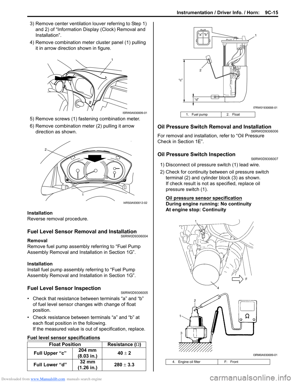
4) Remove combination meter cluster panel (1) pulling
it in arrow direction shown in figure.
5) Remove screws (1) fastening combination meter.
6) Remove combination meter (2) pulling it arrow
direction as shown.
Installation
Reverse removal procedure.
Fuel Level Sensor Removal and InstallationS6RW0D9306004
Removal
Remove fuel pump assembly referring to “Fuel Pump
Assembly Removal and Installation in Section 1G”.
Installation
Install fuel pump assembly referring to “Fuel Pump
Assembly Removal and Installation in Section 1G”.
Fuel Level Sensor InspectionS6RW0D9306005
• Check that resistance between terminals “a” and “b”
of fuel level sensor changes with change of float
position.
• Check resistance between terminals “a” and “b” at
each float position in the following.
If the measured value is out of specification, replace.
Fuel level sensor specifications
Oil Pressure Switch Removal and InstallationS6RW0D9306006
For removal and installation, refer to “Oil Pressure
Check in Section 1E”.
Oil Pressure Switch InspectionS6RW0D9306007
1) Disconnect oil pressure switch (1) lead wire.
2) Check for continuity between oil pressure switch
terminal (2) and cylinder block (3) as shown.
If check result is not as specified, replace oil
pressure switch (1).
Oil pressure sensor specification
During engine running: No continuity
At engine stop: Continuity
Float Position Resistance (Ω)
Full Upper “c”204 mm
(8.03 in.)40 ± 2
Full Lower “d”32 mm
(1.26 in.)280 ± 3.3
1
I5RW0A930009-01
1
2
I4RS0A930012-02
1. Fuel pump 2. Float
4. Engine oil filter F: Front
“c”
“d”
“b” “a”1
2
I7RW01930008-01
I3RM0A930009-01
Page 1412 of 1556
Downloaded from www.Manualslib.com manuals search engine 9F-1 Security and Locks:
Body, Cab and Accessories
Security and Locks
General Description
Key Coding ConstructionS6RW0D9601001
Key Usage and Identification
Key is used for ignition and door lock cylinders. Key is cut on both edges to make them reversible.
Key identification is obtained from five character key code stamped on key code tag. Using this key code, key code
cutting combination can be determined from a code list (available to owners of key cutting equipment from suppliers).
Rear End Door Opener System DescriptionS6RW0D9601002
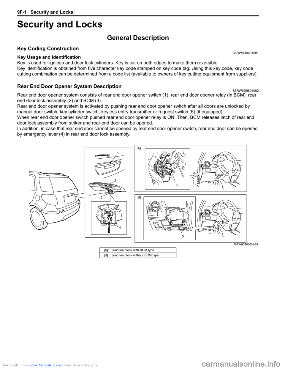
Rear end door opener system consists of rear end door opener switch (1), rear end door opener relay (in BCM), rear
end door lock assembly (2) and BCM (3).
Rear end door opener system is activated by pushing rear end door opener switch after all doors are unlocked by
manual door switch, key cylinder switch, keyless entry transmitter or request switch (5) (if equipped).
When rear end door opener switch pushed rear end door opener relay is ON. Then, BCM releases latch of rear end
door lock assembly from striker and rear end door can be opened.
In addition, in case that rear end door cannot be opened by rear end door opener switch, rear end door can be opened
by emergency lever (4) in rear end door lock assembly.
4
2
1
5
3
[A]
[B]
3
I6RW0C960001-01
[A]: Junction block with BCM type
[B]: Junction block without BCM type
Page 1424 of 1556
Downloaded from www.Manualslib.com manuals search engine 9F-13 Security and Locks:
If check result is not as specified, replace switch.
Replacement of Transmitter Battery (Other than
Keyless Start Model)
S6RW0D9606014
NOTE
For keyless start model, perform
“Replacement of Remote Controller Battery
in Section 10E” instead of “Replacement of
Transmitter Battery (Other than Keyless Start
Model)”.
If transmitter becomes unreliable, replace transmitter
battery as follows.
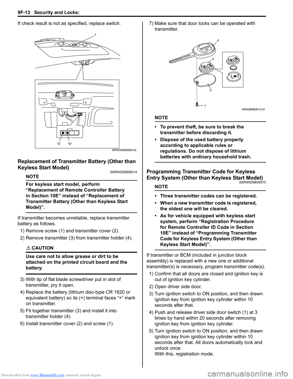
1) Remove screw (1) and transmitter cover (2).
2) Remove transmitter (3) from transmitter holder (4).
CAUTION!
Use care not to allow grease or dirt to be
attached on the printed circuit board and the
battery.
3) With tip of flat blade screwdriver put in slot of
transmitter, pry it open.
4) Replace the battery (lithium disc-type CR 1620 or
equivalent battery) so its (+) terminal faces “+” mark
on transmitter.
5) Fit together transmitter (3) and install it into
transmitter holder (4).
6) Install transmitter cover (2) and screw (1).7) Make sure that door locks can be operated with
transmitter.
NOTE
• To prevent theft, be sure to break the
transmitter before discarding it.
• Dispose of the used battery properly
according to applicable rules or
regulations. Do not dispose of lithium
batteries with ordinary household trash.
Programming Transmitter Code for Keyless
Entry System (Other than Keyless Start Model)
S6RW0D9606015
NOTE
• Three transmitter codes can be registered.
• When a new transmitter code is registered,
the oldest one will be cleared.
• As for vehicle equipped with keyless start
system, perform “Registration Procedure
for Remote Controller ID Code in Section
10E” instead of “Programming Transmitter
Code for Keyless Entry System (Other than
Keyless Start Model)”.
If transmitter or BCM (included in junction block
assembly) is replaced with a new one or additional
transmitter(s) is necessary, program transmitter code(s).
1) Confirm that all doors are closed and ignition key is
out of ignition key cylinder.
2) Open driver side door.
3) Turn ignition switch to ON position, and then drawn
ignition key from ignition key cylinder within 10
seconds after that.
4) Push and release driver side door switch (1) at 3
times by hand within 20 seconds after removing
ignition key from ignition key cylinder.
5) Turn ignition switch to ON position, and then drawn
ignition key from ignition key cylinder within 10
seconds after that. All doors automatically lock and
unlock once.
With this, registration mode.
1
“a”
“b”
I5RW0A960009-02
234
1I4RS0B960014-01
Page 1480 of 1556
Downloaded from www.Manualslib.com manuals search engine 10B-7 Body Electrical Control System:
Component Location
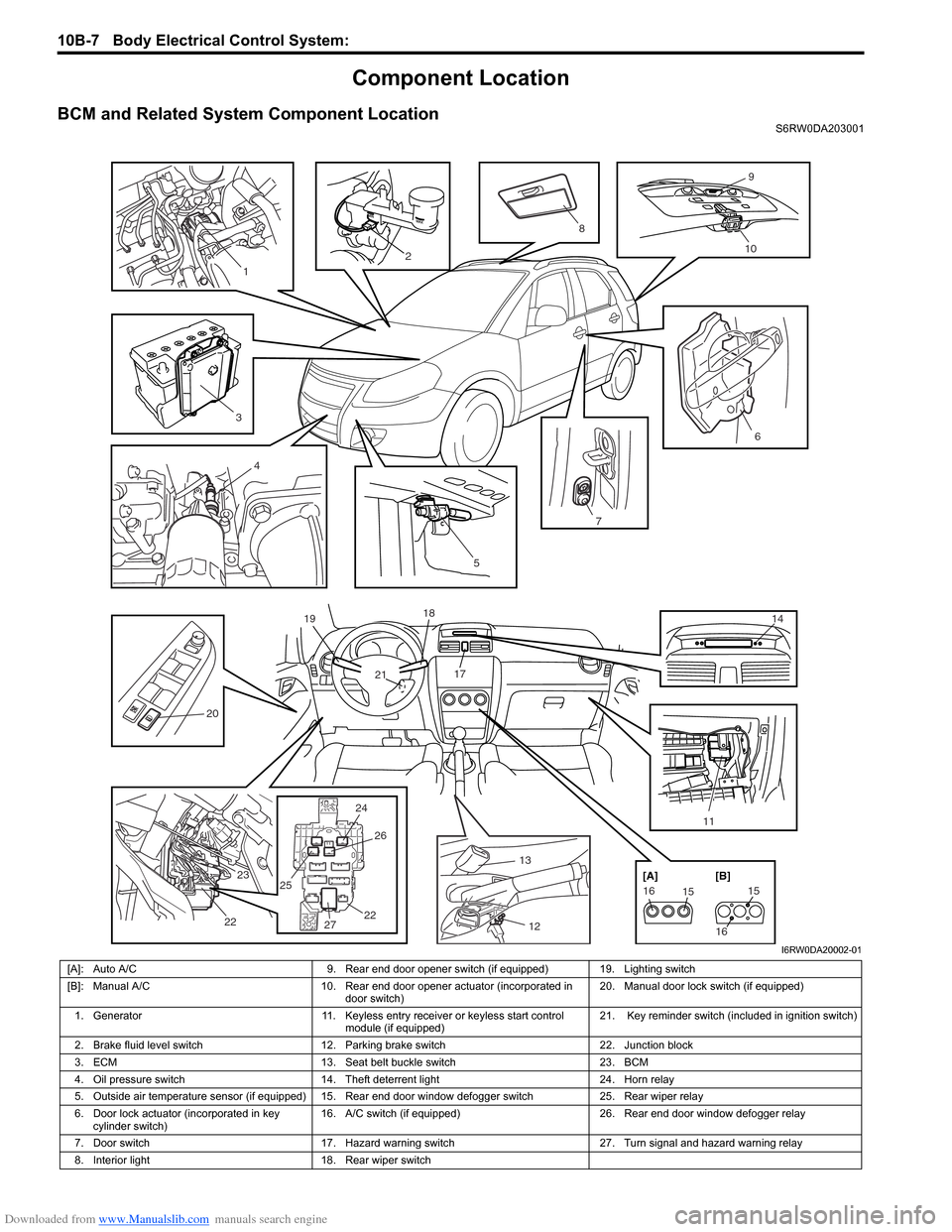
BCM and Related System Component LocationS6RW0DA203001
13
12 17 18
21 19
14
24 25
2526
2722 23
22
2476
20
11
5
151615
16 [A] [B]
2
9
10
3
8
4
1
I6RW0DA20002-01
[A]: Auto A/C 9. Rear end door opener switch (if equipped) 19. Lighting switch
[B]: Manual A/C 10. Rear end door opener actuator (incorporated in
door switch)20. Manual door lock switch (if equipped)
1. Generator 11. Keyless entry receiver or keyless start control
module (if equipped)21. Key reminder switch (included in ignition switch)
2. Brake fluid level switch 12. Parking brake switch 22. Junction block
3. ECM 13. Seat belt buckle switch 23. BCM
4. Oil pressure switch 14. Theft deterrent light 24. Horn relay
5. Outside air temperature sensor (if equipped) 15. Rear end door window defogger switch 25. Rear wiper relay
6. Door lock actuator (incorporated in key
cylinder switch)16. A/C switch (if equipped) 26. Rear end door window defogger relay
7. Door switch 17. Hazard warning switch 27. Turn signal and hazard warning relay
8. Interior light 18. Rear wiper switch
Page 1485 of 1556
Downloaded from www.Manualslib.com manuals search engine Body Electrical Control System: 10B-12
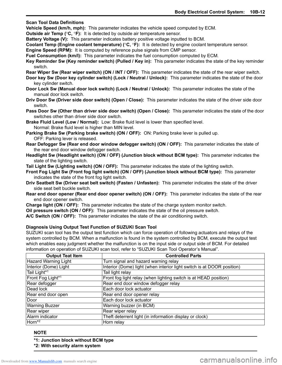
Scan Tool Data Definitions
Vehicle Speed (km/h, mph): This parameter indicates the vehicle speed computed by ECM.
Outside air Temp (°C, °F): It is detected by outside air temperature sensor.
Battery Voltage (V): This parameter indicates battery positive voltage inputted to BCM.
Coolant Temp (Engine coolant temperature) (°C, °F): It is detected by engine coolant temperature sensor.
Engine Speed (RPM): It is computed by reference pulse signals from CMP sensor.
Fuel Consumption (km/l): This parameter indicates the fuel consumption computed by ECM.
Key Reminder Sw (Key reminder switch) (Pulled / Key in): This parameter indicates the state of the key reminder
switch.
Rear Wiper Sw (Rear wiper switch) (ON / INT / OFF): This parameter indicates the state of the rear wiper switch.
Door key Sw (Door key cylinder switch) (Lock / Neutral / Unlock): This parameter indicates the state of the door
key cylinder switch.
Door Lock Sw (Manual door lock switch) (Lock / Neutral / Unlock): This parameter indicates the state of the
manual door lock switch.
Driv Door Sw (Driver side door switch) (Open / Close): This parameter indicates the state of the driver side door
switch.
Pass Door Sw (Other than driver side door switch) (Open / Close): This parameter indicates the state of the door
switches other than driver side door switch.
Brake Fluid Level (Low / Normal): Low: Brake fluid level is lower than specified level.
Normal: Brake fluid level is higher than MIN level.
Parking Brake Sw (Parking brake switch) (ON / OFF): ON: Parking brake lever is pulled up.
OFF: Parking lever is released.
Rear Defogger Sw (Rear end door window defogger switch) (ON / OFF): This parameter indicates the state of
the rear end door window defogger switch.
Headlight Sw (Headlight switch) (ON / OFF) (Junction block without BCM type): This parameter indicates the
state of the lighting switch.
Tail Light Sw (Lighting switch) (ON / OFF): This parameter indicates the state of the lighting switch.
Front Fog Light Sw (Front fog light switch) (ON / OFF) (Junction block without BCM type): This parameter
indicates the state of the front fog light switch.
Driv Seatbelt Sw (Driver seat belt switch) (Fasten / Unfasten): This parameter indicates the state of the driver
side seat belt buckle switch.
Rear end door opener (Rear end door opener switch) (ON / OFF): This parameter indicates the state of the rear
end door opener switch.
Charge light (ON / OFF): This parameter indicates the state of the charge system monitor switch.
Oil pressure switch (ON / OFF): This parameter indicates the state of the oil pressure switch.
A/C Switch (ON / OFF): This parameter indicates the state of the air conditioning switch.
Diagnosis Using Output Test Function of SUZUKI Scan Tool
SUZUKI scan tool has the output test function which can force operation of following actuators and relays of the
system controlled by BCM. When a malfunction is found in the system controlled by BCM, execute the output test
which enables easy judgment whether the malfunction is on the input side or output side of BCM. For detailed
information on operation of SUZUKI scan tool, refer to “SUZUKI Scan Tool Operator’s Manual”.
NOTE
*1: Junction block without BCM type
*2: With security alarm system
Output Teat Item Controlled Parts
Hazard Warning Light Turn signal and hazard warning relay
Interior (Dome) Light Interior (Dome) light (when interior light switch is at DOOR position)
Tail Light*
1Tail light relay
Front Fog Light*1Front fog light relay (when lighting switch is at HEAD position)
Rear defogger Rear end door window defogger relay
Dead lock Each door lock actuator
Rear end door open Rear end door opener relay
Door Each door lock actuator
Warning Buzzer Warning buzzer (in BCM)
Rear wiper Rear wiper relay
Alarm indicator Theft deterrent light (in information display or clock)
Horn*
2Horn relay
Page 1498 of 1556
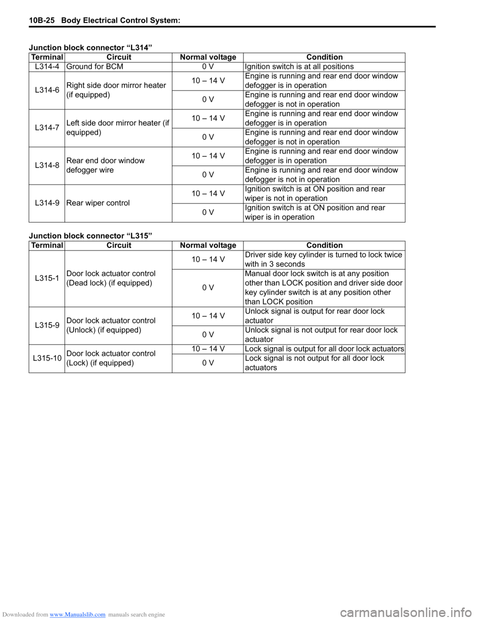
Downloaded from www.Manualslib.com manuals search engine 10B-25 Body Electrical Control System:
Junction block connector “L314”
Junction block connector “L315”Terminal Circuit Normal voltage Condition
L314-4 Ground for BCM 0 V Ignition switch is at all positions
L314-6Right side door mirror heater
(if equipped)10 – 14 VEngine is running and rear end door window
defogger is in operation
0 VEngine is running and rear end door window
defogger is not in operation
L314-7Left side door mirror heater (if
equipped)10 – 14 VEngine is running and rear end door window
defogger is in operation
0 VEngine is running and rear end door window
defogger is not in operation
L314-8Rear end door window
defogger wire10 – 14 VEngine is running and rear end door window
defogger is in operation
0 VEngine is running and rear end door window
defogger is not in operation
L314-9 Rear wiper control10 – 14 VIgnition switch is at ON position and rear
wiper is not in operation
0 VIgnition switch is at ON position and rear
wiper is in operation
Terminal Circuit Normal voltage Condition
L315-1Door lock actuator control
(Dead lock) (if equipped)10 – 14 VDriver side key cylinder is turned to lock twice
with in 3 seconds
0 VManual door lock switch is at any position
other than LOCK position and driver side door
key cylinder switch is at any position other
than LOCK position
L315-9Door lock actuator control
(Unlock) (if equipped)10 – 14 VUnlock signal is output for rear door lock
actuator
0 VUnlock signal is not output for rear door lock
actuator
L315-10Door lock actuator control
(Lock) (if equipped)10 – 14 V Lock signal is output for all door lock actuators
0 VLock signal is not output for all door lock
actuators