2006 SUZUKI SX4 Hub
[x] Cancel search: HubPage 799 of 1556

Downloaded from www.Manualslib.com manuals search engine Automatic Transmission/Transaxle: 5A-151
39) After applying A/T fluid to intermediate shaft thrust
bearing rear race (3), thrust bearing (2) and front
race (1), install them to forward and reverse clutch
assembly (4).
Bearing race dimension
40) Apply A/T fluid to forward and reverse clutch
assembly (1).
Install forward and reverse clutch assembly while
rotating clockwise and counterclockwise frequently
to fit clutch discs to mating hubs.
NOTE
Before installation, align teeth of forward and
reverse clutch discs to facilitate installation.
41) Check for correct installation of forward and reverse
clutch assembly as follows.
Measure distance “a” by using micrometer caliper (1)
and straightedge (2). If out of specification, remove
forward and reverse clutch assembly, forward clutch
hub, rear planetary sun gear subassembly and one-
way clutch No.1 assembly, and reinstall them
properly.
Distance between forward and reverse clutch
assembly and mating surface of transaxle case
“a”: 27.1 – 29.4 mm (1.067 – 1.157 in.)
42) After applying A/T fluid to O/D and 2nd coast brake
retaining plate (4), separator plate (3), discs (2) and
rear plate (1), install them to transaxle case (5). Front race Rear race
Outside
diameter30.6 mm (1.20 in.) 28.2 mm (1.11 in.)
Thickness 2.0 mm (0.08 in.) 2.0 mm (0.08 in.)
I2RH0B510294-01
I2RH0B510295-01
“a”
“a”
1
2
I2RH0B510296-01
I2RH0B510297-01
Page 801 of 1556

Downloaded from www.Manualslib.com manuals search engine Automatic Transmission/Transaxle: 5A-153
48) Install transaxle rear cover assembly on transaxle
case.
49) Install hook (2) to location shown in figure.
50) Tighten rear cover bolts (1).
Tightening torque
Rear cover bolt (a): 25 N·m (2.5 kgf-m, 18.0 lb-ft)
51) Install fluid reservoir LH plate (1).
Tightening torque
Fluid reservoir LH plate bolt (a): 10 N·m (1.0 kgf-
m, 7.5 lb-ft)
52) After applying A/T fluid to new governor apply No.2
gasket (1), install it to transaxle case.53) After applying A/T fluid to differential assembly (1)
and countershaft assembly (2), install them to
transaxle case.
54) After applying A/T fluid to direct clutch hub (1), install
it to planetary gear assembly.
55) After applying A/T fluid to input shaft rear thrust
bearing (1) and thrust bearing race (2), install them
into direct clutch hub (3).
56) After applying A/T fluid to input shaft front thrust
bearing (1), install it to direct clutch assembly (2).
I3RM0B510068-01
I2RH0B510303-01
I2RH0B510304-01
1
2
I4RS0A510036-01
I2RH0B510306-01
I2RH0B510307-01
I2RH0B510308-01
Page 802 of 1556

Downloaded from www.Manualslib.com manuals search engine 5A-154 Automatic Transmission/Transaxle:
57) Apply A/T fluid to direct clutch assembly (1).
Install direct clutch assembly while rotating
clockwise and counterclockwise frequently to fit
clutch discs to mating hub.
NOTE
Before installation, align teeth of direct clutch
discs to facilitate installation.
58) Check for correct installation of direct clutch
assembly as follows.
Measure distance “a” by using micrometer caliper (1)
and straightedge (2). If out of specification, remove
direct clutch assembly, direct clutch hub and reinstall
them properly.
Distance between direct clutch assembly and
mating surface of transaxle case
“a”: 10.5 – 11.3 mm (0.413 – 0.445 in.)59) Install oil pump assembly (1) to transaxle case.
Tightening torque
Oil pump assembly bolt (a): 25 N·m (2.5 kgf-m,
18.0 lb-ft)
60) Make sure that input shaft (1) turns smoothly.
I2RH0B510309-01
“a”
“a”
1
2
I2RH0B510310-01
I2RH0B510311-01
I2RH0B510312-01
Page 808 of 1556

Downloaded from www.Manualslib.com manuals search engine 5A-160 Automatic Transmission/Transaxle:
94) Install manual select lever (1).
Tightening torque
Manual select lever nut (a): 13 N·m (1.3 kgf-m,
9.5 lb-ft)
95) Install engine mounting LH bracket (1). Tighten
engine mounting LH bracket bolts and nut to
specified torque referring to “Engine Mountings
Components in Section 1D”.
96) Install torque converter (3) noting the following
points.
CAUTION!
• Before installing converter, make sure that
its pump hub portion is free from nicks,
burrs or damage which may cause oil seal
to leak.
• Be very careful not to drop converter on oil
pump gear. Damage in gear, should it
occur, may cause a critical trouble.
• Install torque converter aligning grooves (1) of
torque converter and projection (2) of oil pump
drive gear.
• Install torque converter, using care not to damage
oil seal of oil pump.
• After installing torque converter, check that
distance “a” is within specification.
Torque converter installing position
“a”: More than 19.9 mm (0.783 in.)
• Check torque converter for smooth rotation.
• Apply grease around cup (6) at the center of
torque converter.
“C”: Grease 99000–25011 (SUZUKI Super
Grease A)
1(a)I2RH0B510335-01
1
I5RW0C510058-01
4. Flange nut
5. Torque converter housing
I2RH0B510337-01
Page 813 of 1556

Downloaded from www.Manualslib.com manuals search engine Manual Transmission/Transaxle: 5B-1
Transmission / Transaxle
Manual Transmission/Transaxle
General Description
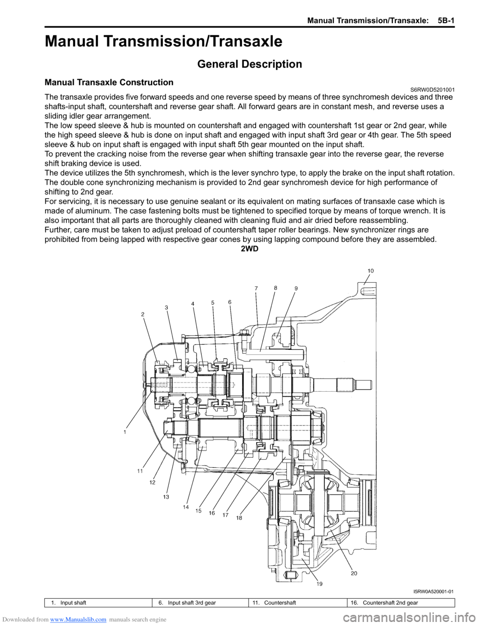
Manual Transaxle ConstructionS6RW0D5201001
The transaxle provides five forward speeds and one reverse speed by means of three synchromesh devices and three
shafts-input shaft, countershaft and reverse gear shaft. All forward gears are in constant mesh, and reverse uses a
sliding idler gear arrangement.
The low speed sleeve & hub is mounted on countershaft and engaged with countershaft 1st gear or 2nd gear, while
the high speed sleeve & hub is done on input shaft and engaged with input shaft 3rd gear or 4th gear. The 5th speed
sleeve & hub on input shaft is engaged with input shaft 5th gear mounted on the input shaft.
To prevent the cracking noise from the reverse gear when shifting transaxle gear into the reverse gear, the reverse
shift braking device is used.
The device utilizes the 5th synchromesh, which is the lever synchro type, to apply the brake on the input shaft rotation.
The double cone synchronizing mechanism is provided to 2nd gear synchromesh device for high performance of
shifting to 2nd gear.
For servicing, it is necessary to use genuine sealant or its equivalent on mating surfaces of transaxle case which is
made of aluminum. The case fastening bolts must be tightened to specified torque by means of torque wrench. It is
also important that all parts are thoroughly cleaned with cleaning fluid and air dried before reassembling.
Further, care must be taken to adjust preload of countershaft taper roller bearings. New synchronizer rings are
prohibited from being lapped with respective gear cones by using lapping compound before they are assembled.
2WD
I5RW0A520001-01
1. Input shaft 6. Input shaft 3rd gear 11. Countershaft 16. Countershaft 2nd gear
Page 814 of 1556

Downloaded from www.Manualslib.com manuals search engine 5B-2 Manual Transmission/Transaxle:
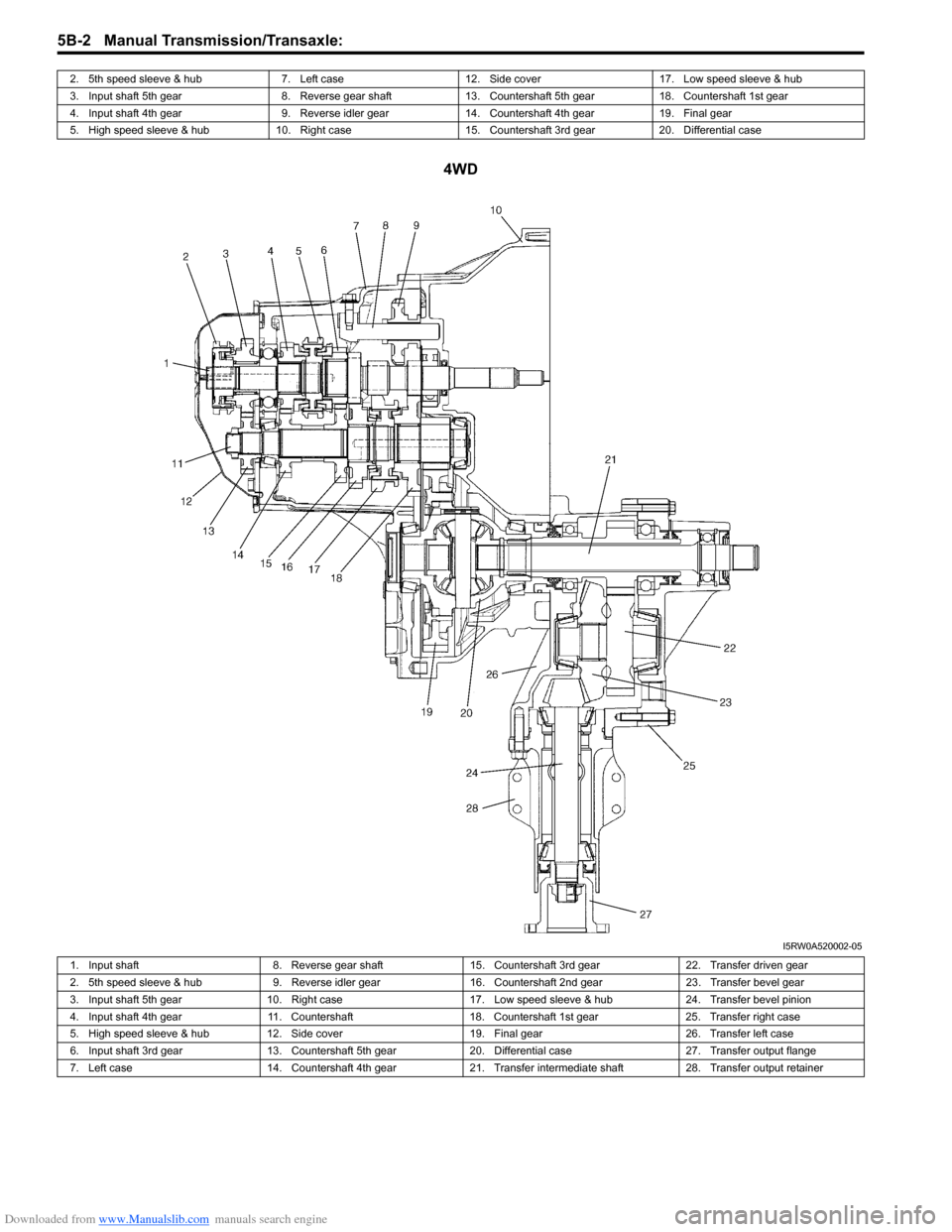
4WD
2. 5th speed sleeve & hub 7. Left case 12. Side cover 17. Low speed sleeve & hub
3. Input shaft 5th gear 8. Reverse gear shaft 13. Countershaft 5th gear 18. Countershaft 1st gear
4. Input shaft 4th gear 9. Reverse idler gear 14. Countershaft 4th gear 19. Final gear
5. High speed sleeve & hub 10. Right case 15. Countershaft 3rd gear 20. Differential case
I5RW0A520002-05
1. Input shaft 8. Reverse gear shaft 15. Countershaft 3rd gear 22. Transfer driven gear
2. 5th speed sleeve & hub 9. Reverse idler gear 16. Countershaft 2nd gear 23. Transfer bevel gear
3. Input shaft 5th gear 10. Right case 17. Low speed sleeve & hub 24. Transfer bevel pinion
4. Input shaft 4th gear 11. Countershaft 18. Countershaft 1st gear 25. Transfer right case
5. High speed sleeve & hub 12. Side cover 19. Final gear 26. Transfer left case
6. Input shaft 3rd gear 13. Countershaft 5th gear 20. Differential case 27. Transfer output flange
7. Left case 14. Countershaft 4th gear 21. Transfer intermediate shaft 28. Transfer output retainer
Page 829 of 1556

Downloaded from www.Manualslib.com manuals search engine Manual Transmission/Transaxle: 5B-17
Fifth Gear Disassembly and ReassemblyS6RW0D5206015
Disassembly
1) Remove cover bolts and take off transaxle side
cover.
CAUTION!
Care should be taken not to distort side cover
when it is removed from left case.
2) Using special tool, remove circlip (1).
Special tool
: 09900–06107
3) Remove shift fork shaft bolt (2).
4) Remove gear shift fork (3) and 5th gear all together.
Use gear puller for removal if spline fitting of hub is
tight.5) Unfasten caulking of countershaft nut (2), install
input shaft 5th gear (1) and special tool to stop
rotation of shafts, and then remove countershaft nut
(2).
Special tool
(A): 09927–76060
6) Remove input shaft 5th gear, needle bearing and
then countershaft 5th gear (1). Gear puller (2) would
be necessary if spline fitting of countershaft 5th gear
is tight.
10. Oil drain plug
: Apply sealant 99000-31260 to all around thread part of plug.31. Reverse shaft bolt
: Apply sealant 99000-31260 to thread part of bolt.
11. Oil gutter bolt
: Apply thread lock 99000-32110 to all around thread part of bolt.32. Washer
12. Left case plate bolt
: Apply thread lock 99000-32110 to all around thread part of bolt.33. Oil seal
: Apply SUZUKI SUPER GREASE A
99000-25010 to Oil seal lip.
13. Side cover bolts 34. Outer race
14. Transaxle case bolts 35. Shim
15. 5th speed synchronizer ring 36. Oil gutter
16. 5th speed synchronizer lever : 21 N⋅m (2.1 kgf-m, 15.5 lb-ft)
17. 5th speed sleeve & hub : 23 N⋅m (2.3 kgf-m, 17.0 lb-ft)
18. Circlip: 10 N⋅m (1.0 kgf-m, 7.5 lb-ft)
19. Bearing set shim : 100 N⋅m (10.0 kgf-m, 72.5 lb-ft)
20. Countershaft 5th gear : Do not reuse.
21. Countershaft nut
: After tightening nut to specified torque, caulk nut securely.: Apply transaxle oil.
32
1
I4RH01520015-01
(A)
2
1
I4RH01520016-01
I4RH01520017-01
Page 830 of 1556

Downloaded from www.Manualslib.com manuals search engine 5B-18 Manual Transmission/Transaxle:
Reassembly
1) Install countershaft 5th gear (1) to countershaft
facing machined boss “A” inward.
2) Apply transaxle oil to needle bearing, and install it to
input shaft.
3) Install input shaft 5th gear (1) to input shaft.
4) Install special tool in order to stop shaft rotation.
Special tool
(A): 09927–76060
5) Tighten new countershaft nut (2) to specified torque,
and caulk nut securely.
Tightening torque
Countershaft nut (a): 100 N·m (10.0 kgf-m, 75.0
lb-ft)
6) Assemble 5th speed synchronizer sleeve (1), hub
(2), 5th speed synchronizer levers (3) and
synchronizer ring (4) as follows.a) Install hub (1) to 5th speed synchronizer sleeve
(2) in specified direction as shown in figure.
b) Fit 5th speed synchronizer levers (1) to hub (2) in
specified position as shown in figure.
NOTE
Align protrusion “A” of 5th speed
synchronizer levers (1) with groove of hub
(2).
c) Install synchronizer ring (1) to hub (2) in
specified direction as shown in figure.
A: Machined boss (Inside)
B: No machining (Outside)
I2RH01520088-01
(A)
2, (a)
1
I4RH01520047-01
I4RH01520054-01
A: Chamfered side
B: Long boss
1
2 B
A
I4RH01520048-01
1A
2 A
I4RH01520049-01
1
2
I4RH01520055-01