2006 SUZUKI SX4 DTC
[x] Cancel search: DTCPage 1482 of 1556
Downloaded from www.Manualslib.com manuals search engine 10B-9 Body Electrical Control System:
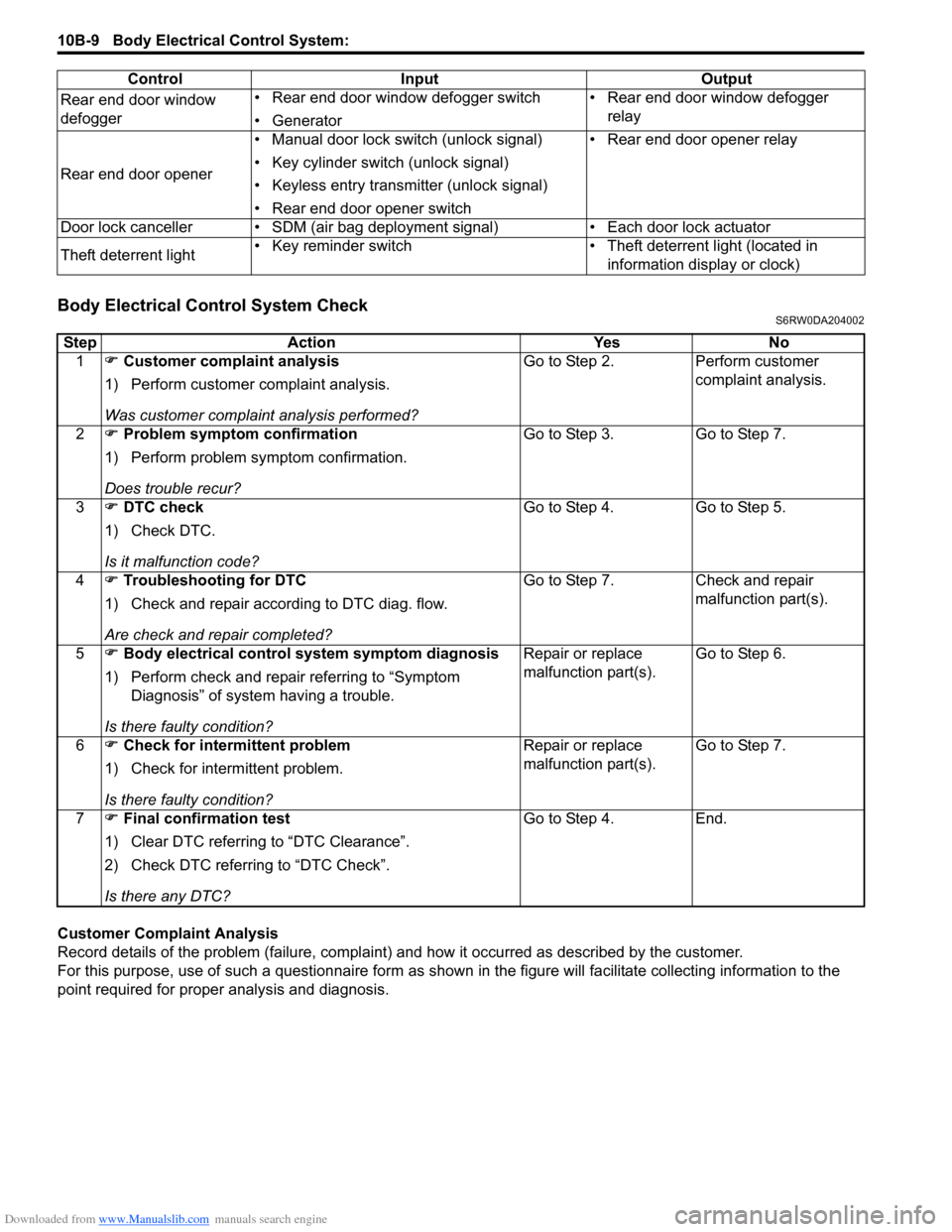
Body Electrical Control System CheckS6RW0DA204002
Customer Complaint Analysis
Record details of the problem (failure, complaint) and how it occurred as described by the customer.
For this purpose, use of such a questionnaire form as shown in the figure will facilitate collecting information to the
point required for proper analysis and diagnosis.Rear end door window
defogger• Rear end door window defogger switch
• Generator• Rear end door window defogger
relay
Rear end door opener• Manual door lock switch (unlock signal)
• Key cylinder switch (unlock signal)
• Keyless entry transmitter (unlock signal)
• Rear end door opener switch• Rear end door opener relay
Door lock canceller • SDM (air bag deployment signal) • Each door lock actuator
Theft deterrent light• Key reminder switch • Theft deterrent light (located in
information display or clock) Control Input Output
Step Action Yes No
1�) Customer complaint analysis
1) Perform customer complaint analysis.
Was customer complaint analysis performed?Go to Step 2. Perform customer
complaint analysis.
2�) Problem symptom confirmation
1) Perform problem symptom confirmation.
Does trouble recur?Go to Step 3. Go to Step 7.
3�) DTC check
1) Check DTC.
Is it malfunction code?Go to Step 4. Go to Step 5.
4�) Troubleshooting for DTC
1) Check and repair according to DTC diag. flow.
Are check and repair completed?Go to Step 7. Check and repair
malfunction part(s).
5�) Body electrical control system symptom diagnosis
1) Perform check and repair referring to “Symptom
Diagnosis” of system having a trouble.
Is there faulty condition?Repair or replace
malfunction part(s).Go to Step 6.
6�) Check for intermittent problem
1) Check for intermittent problem.
Is there faulty condition?Repair or replace
malfunction part(s).Go to Step 7.
7�) Final confirmation test
1) Clear DTC referring to “DTC Clearance”.
2) Check DTC referring to “DTC Check”.
Is there any DTC?Go to Step 4. End.
Page 1483 of 1556
Downloaded from www.Manualslib.com manuals search engine Body Electrical Control System: 10B-10
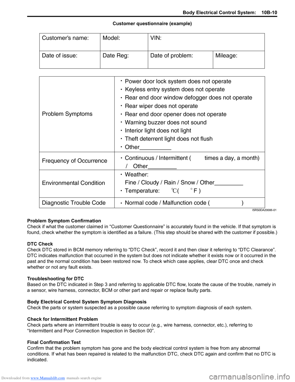
Customer questionnaire (example)
Problem Symptom Confirmation
Check if what the customer claimed in “Customer Questionnaire” is accurately found in the vehicle. If that symptom is
found, check whether the symptom is identified as a failure. (This step should be shared with the customer if possible.)
DTC Check
Check DTC stored in BCM memory referring to “DTC Check”, record it and then clear it referring to “DTC Clearance”.
DTC indicates malfunction that occurred in the system but does not indicate whether it exists now or it occurred in the
past and the normal condition has been restored now. To check which case applies, clear DTC once and check
whether or not any fault exists.
Troubleshooting for DTC
Based on the DTC indicated in Step 3 and referring to applicable DTC flow, locate the cause of the trouble, namely in
a sensor, wire harness, connector, BCM or other part and repair or replace faulty parts.
Body Electrical Control System Symptom Diagnosis
Check the parts or system suspected as a possible cause referring to symptom diagnosis of each system.
Check for Intermittent Problem
Check parts where an intermittent trouble is easy to occur (e.g., wire harness, connector, etc.), referring to
“Intermittent and Poor Connection Inspection in Section 00”.
Final Confirmation Test
Confirm that the problem symptom has gone and the body electrical control system is free from any abnormal
conditions. If what has been repaired is related to the malfunction DTC, check DTC again and confirm that no DTC is
indicated.
Customers name:
Model:
VIN:
Date of issue:
Date Reg:
Date of problem:
Mileage:
Problem Symptoms
Power door lock system does not operate
Keyless entry system does not operate
Rear end door window defogger does not operate
Rear wiper does not operate
Rear end door opener does not operate
Other
Frequency of Occurrence
Continuous / Intermittent ( times a day, a month)
/ Other
Environmental Condition
Weather:
Fine / Cloudy / Rain / Snow / Other
Temperature: (F )
Diagnostic Trouble Code
Normal code / Malfunction code ( )
Warning buzzer does not sound
Interior light does not light
Theft deterrent light does not flush
I5RS0DA20006-01
Page 1486 of 1556
Downloaded from www.Manualslib.com manuals search engine 10B-13 Body Electrical Control System:
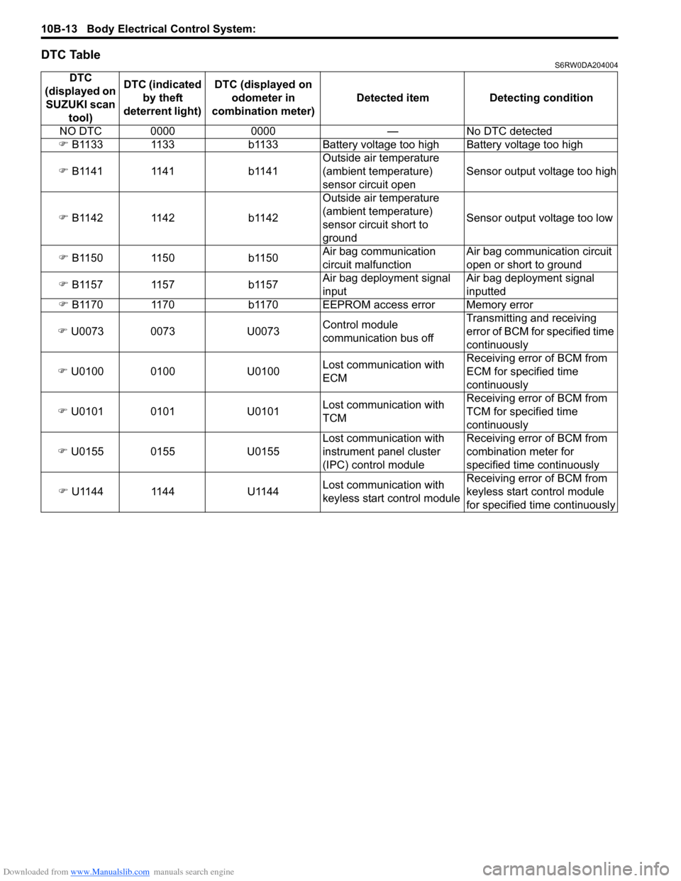
DTC TableS6RW0DA204004
DTC
(displayed on
SUZUKI scan
tool)DTC (indicated
by theft
deterrent light) DTC (displayed on
odometer in
combination meter) Detected item Detecting condition
NO DTC 0000 0000 — No DTC detected
�) B1133 1133 b1133 Battery voltage too high Battery voltage too high
�) B1141 1141 b1141Outside air temperature
(ambient temperature)
sensor circuit openSensor output voltage too high
�) B1142 1142 b1142Outside air temperature
(ambient temperature)
sensor circuit short to
groundSensor output voltage too low
�) B1150 1150 b1150Air bag communication
circuit malfunctionAir bag communication circuit
open or short to ground
�) B1157 1157 b1157Air bag deployment signal
inputAir bag deployment signal
inputted
�) B1170 1170 b1170 EEPROM access error Memory error
�) U0073 0073 U0073Control module
communication bus offTransmitting and receiving
error of BCM for specified time
continuously
�) U0100 0100 U0100Lost communication with
ECMReceiving error of BCM from
ECM for specified time
continuously
�) U0101 0101 U0101Lost communication with
TCMReceiving error of BCM from
TCM for specified time
continuously
�) U0155 0155 U0155Lost communication with
instrument panel cluster
(IPC) control moduleReceiving error of BCM from
combination meter for
specified time continuously
�) U1144 1144 U1144Lost communication with
keyless start control moduleReceiving error of BCM from
keyless start control module
for specified time continuously
Page 1487 of 1556
Downloaded from www.Manualslib.com manuals search engine Body Electrical Control System: 10B-14
DTC CheckS6RW0DA204005
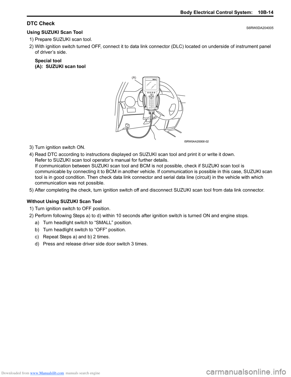
Using SUZUKI Scan Tool
1) Prepare SUZUKI scan tool.
2) With ignition switch turned OFF, connect it to data link connector (DLC) located on underside of instrument panel
of driver’s side.
Special tool
(A): SUZUKI scan tool
3) Turn ignition switch ON.
4) Read DTC according to instructions displayed on SUZUKI scan tool and print it or write it down.
Refer to SUZUKI scan tool operator’s manual for further details.
If communication between SUZUKI scan tool and BCM is not possible, check if SUZUKI scan tool is
communicable by connecting it to BCM in another vehicle. If communication is possible in this case, SUZUKI scan
tool is in good condition. Then check data link connector and serial data line (circuit) in the vehicle with which
communication was not possible.
5) After completing the check, turn ignition switch off and disconnect SUZUKI scan tool from data link connector.
Without Using SUZUKI Scan Tool
1) Turn ignition switch to OFF position.
2) Perform following Steps a) to d) within 10 seconds after ignition switch is turned ON and engine stops.
a) Turn headlight switch to “SMALL” position.
b) Turn headlight switch to “OFF” position.
c) Repeat Steps a) and b) 2 times.
d) Press and release driver side door switch 3 times.
(A)
I5RW0AA20008-02
Page 1488 of 1556
Downloaded from www.Manualslib.com manuals search engine 10B-15 Body Electrical Control System:
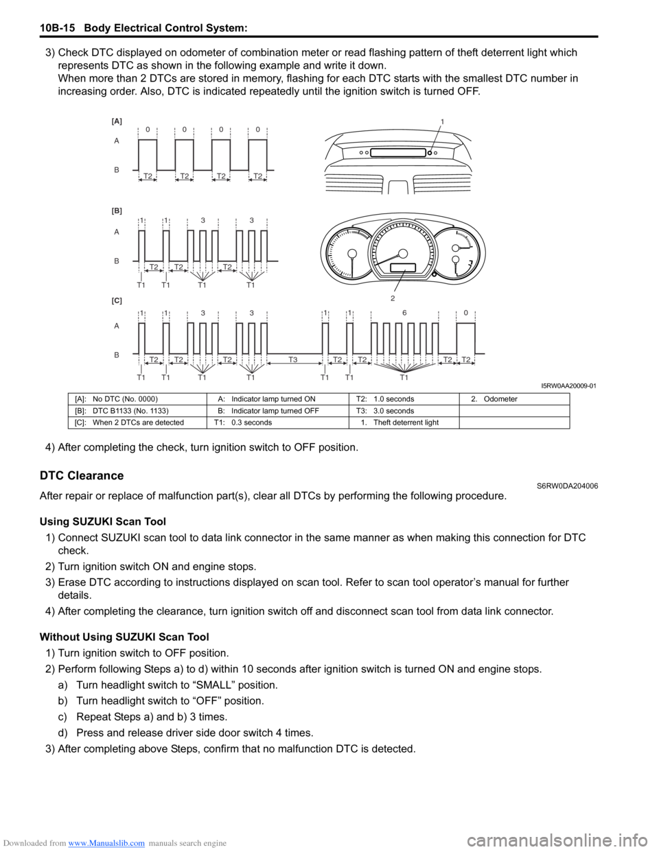
3) Check DTC displayed on odometer of combination meter or read flashing pattern of theft deterrent light which
represents DTC as shown in the following example and write it down.
When more than 2 DTCs are stored in memory, flashing for each DTC starts with the smallest DTC number in
increasing order. Also, DTC is indicated repeatedly until the ignition switch is turned OFF.
4) After completing the check, turn ignition switch to OFF position.
DTC ClearanceS6RW0DA204006
After repair or replace of malfunction part(s), clear all DTCs by performing the following procedure.
Using SUZUKI Scan Tool
1) Connect SUZUKI scan tool to data link connector in the same manner as when making this connection for DTC
check.
2) Turn ignition switch ON and engine stops.
3) Erase DTC according to instructions displayed on scan tool. Refer to scan tool operator’s manual for further
details.
4) After completing the clearance, turn ignition switch off and disconnect scan tool from data link connector.
Without Using SUZUKI Scan Tool
1) Turn ignition switch to OFF position.
2) Perform following Steps a) to d) within 10 seconds after ignition switch is turned ON and engine stops.
a) Turn headlight switch to “SMALL” position.
b) Turn headlight switch to “OFF” position.
c) Repeat Steps a) and b) 3 times.
d) Press and release driver side door switch 4 times.
3) After completing above Steps, confirm that no malfunction DTC is detected.
B A [B] [A]
[C]
B A B A
3 113
3 113 T2
T1 T1 T1T1
1
2
T2T2
T2
T1 T1 T1T1T2T2
0
T2
0
T2
0
T2
0
T2
11 6 0
T1 T1 T1
T2 T3T2T2T2
I5RW0AA20009-01
[A]: No DTC (No. 0000) A: Indicator lamp turned ON T2: 1.0 seconds 2. Odometer
[B]: DTC B1133 (No. 1133) B: Indicator lamp turned OFF T3: 3.0 seconds
[C]: When 2 DTCs are detected T1: 0.3 seconds 1. Theft deterrent light
Page 1490 of 1556
Downloaded from www.Manualslib.com manuals search engine 10B-17 Body Electrical Control System:
DTC B1133 (DTC No. 1133): Battery Voltage Too HighS6RW0DA204008
Wiring Diagram
Refer to “BCM Power Circuit and Ground Circuit Check”.
DTC Detecting Condition and Possible Cause
Flow Test Description
Step 1: Check charging system
DTC Troubleshooting4Ground circuit check
1) Turn ignition switch to OFF position.
2) Check for proper connection to junction block connector
at terminals “G271-3”, “G272-9” and “L314-4”.
3) If OK, then measure resistance between following
terminals.
• Between “G271-3” terminal of junction block
connector and vehicle body ground
• Between “G272-9” terminal of junction block
connector and vehicle body ground
• Between “L314-4” terminal of junction block connector
and vehicle body ground
Is each resistance 2
Ω or less?BCM power supply
circuit and ground circuit
are in good condition.Repair ground circuit. Step Action Yes No
DTC detecting condition Possible cause
Power voltage supplied from battery to BCM is
higher than 16V.• Charging system malfunction
• BCM malfunction
Step Action Yes No
1Charging system operation check
1) Check generator for operation referring to “Generator
Test (Overcharged Battery Check) in Section 1J”.
Is it in good condition?Substitute a known
good BCM (included in
junction block) and
recheck.Repair charging system.
Page 1491 of 1556
Downloaded from www.Manualslib.com manuals search engine Body Electrical Control System: 10B-18
DTC B1141 / DTC B1142 (No. 1141 / No. 1142) Outside Air Temperature (Ambient Temp.) Sensor
Circuit Malfunction
S6RW0DA204009
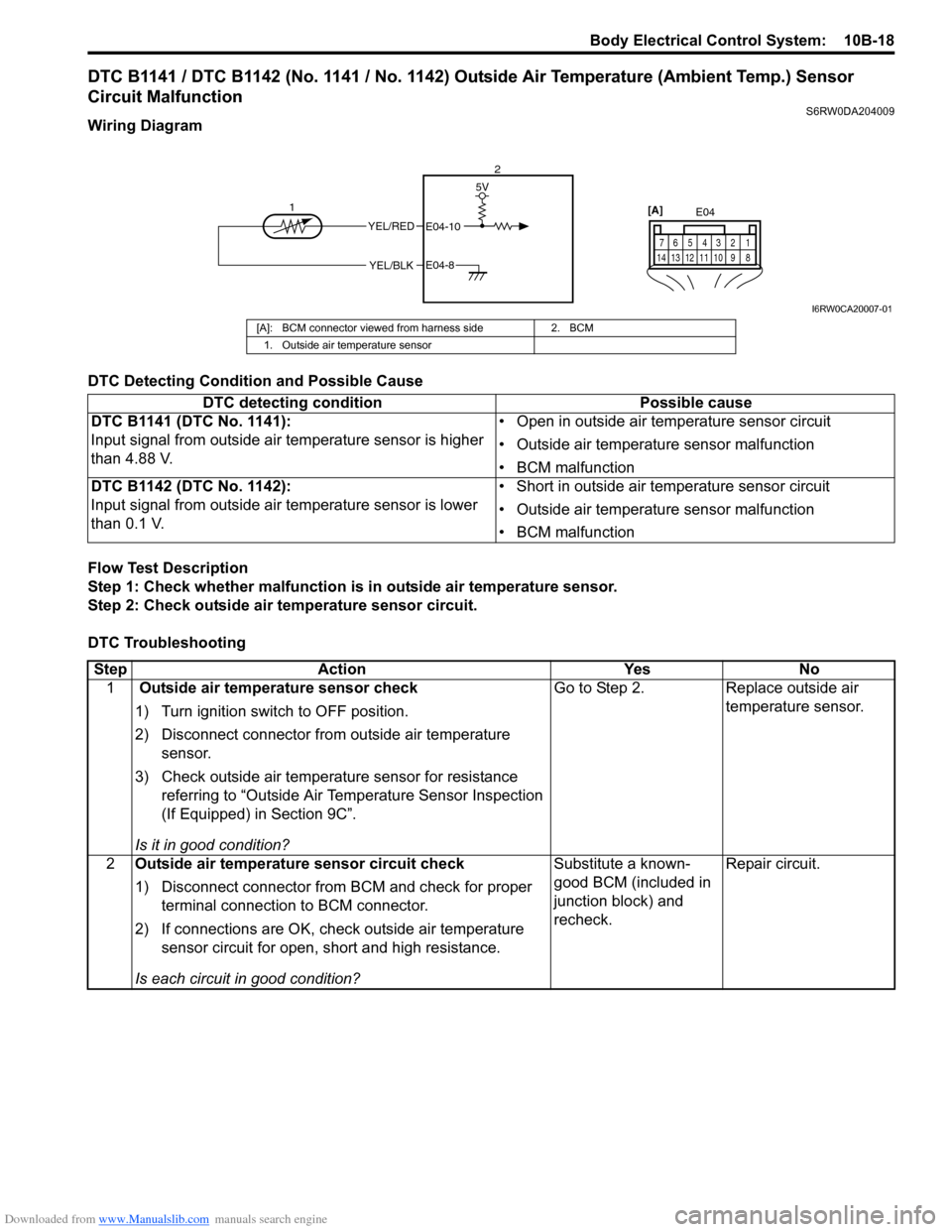
Wiring Diagram
DTC Detecting Condition and Possible Cause
Flow Test Description
Step 1: Check whether malfunction is in outside air temperature sensor.
Step 2: Check outside air temperature sensor circuit.
DTC Troubleshooting
YEL/RED
YEL/BLK
5V
E04-10
E04-8
12E04
1 2 4 53 6 7
8 9 10 11 12 13 14
[A]
I6RW0CA20007-01
[A]: BCM connector viewed from harness side 2. BCM
1. Outside air temperature sensor
DTC detecting condition Possible cause
DTC B1141 (DTC No. 1141):
Input signal from outside air temperature sensor is higher
than 4.88 V.• Open in outside air temperature sensor circuit
• Outside air temperature sensor malfunction
• BCM malfunction
DTC B1142 (DTC No. 1142):
Input signal from outside air temperature sensor is lower
than 0.1 V.• Short in outside air temperature sensor circuit
• Outside air temperature sensor malfunction
• BCM malfunction
Step Action Yes No
1 Outside air temperature sensor check
1) Turn ignition switch to OFF position.
2) Disconnect connector from outside air temperature
sensor.
3) Check outside air temperature sensor for resistance
referring to “Outside Air Temperature Sensor Inspection
(If Equipped) in Section 9C”.
Is it in good condition?Go to Step 2. Replace outside air
temperature sensor.
2Outside air temperature sensor circuit check
1) Disconnect connector from BCM and check for proper
terminal connection to BCM connector.
2) If connections are OK, check outside air temperature
sensor circuit for open, short and high resistance.
Is each circuit in good condition?Substitute a known-
good BCM (included in
junction block) and
recheck.Repair circuit.
Page 1492 of 1556
Downloaded from www.Manualslib.com manuals search engine 10B-19 Body Electrical Control System:
DTC B1150 (No. 1150): Air Bag Communication Circuit MalfunctionS6RW0DA204010
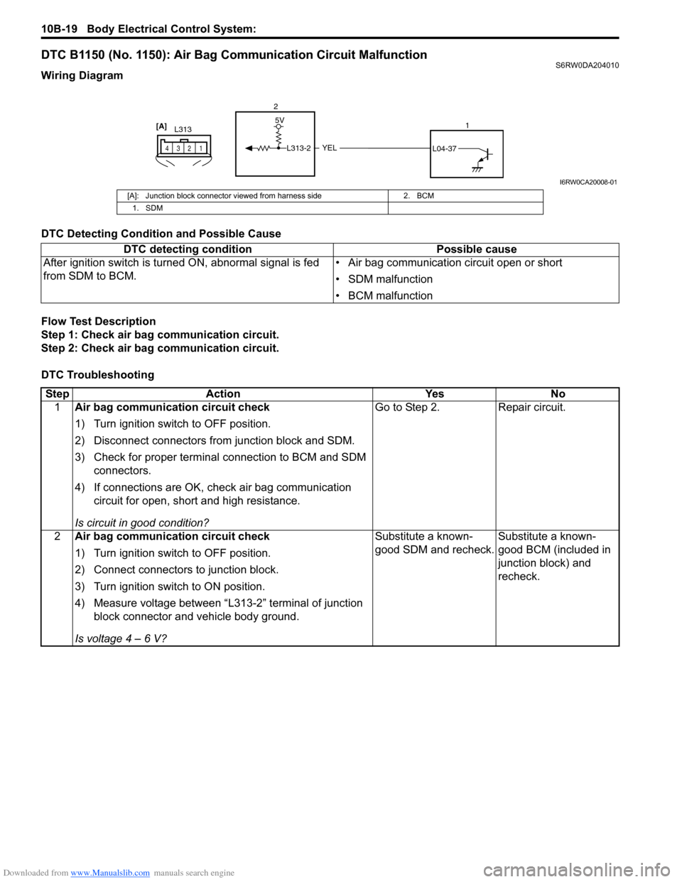
Wiring Diagram
DTC Detecting Condition and Possible Cause
Flow Test Description
Step 1: Check air bag communication circuit.
Step 2: Check air bag communication circuit.
DTC Troubleshooting
YEL
5V
L313-2L04-37
2
1
L313
1 2 43
[A]
I6RW0CA20008-01
[A]: Junction block connector viewed from harness side 2. BCM
1. SDM
DTC detecting condition Possible cause
After ignition switch is turned ON, abnormal signal is fed
from SDM to BCM.• Air bag communication circuit open or short
• SDM malfunction
• BCM malfunction
Step Action Yes No
1Air bag communication circuit check
1) Turn ignition switch to OFF position.
2) Disconnect connectors from junction block and SDM.
3) Check for proper terminal connection to BCM and SDM
connectors.
4) If connections are OK, check air bag communication
circuit for open, short and high resistance.
Is circuit in good condition?Go to Step 2. Repair circuit.
2Air bag communication circuit check
1) Turn ignition switch to OFF position.
2) Connect connectors to junction block.
3) Turn ignition switch to ON position.
4) Measure voltage between “L313-2” terminal of junction
block connector and vehicle body ground.
Is voltage 4 – 6 V?Substitute a known-
good SDM and recheck.Substitute a known-
good BCM (included in
junction block) and
recheck.