2006 SUZUKI SX4 DTC
[x] Cancel search: DTCPage 1119 of 1556
Downloaded from www.Manualslib.com manuals search engine Air Bag System: 8B-80
NOTE
Upon completion of inspection and repair work, perform the following items.
• Reconnect all air bag system components, ensure all components are properly mounted.
• Clear DTCs referring to “DTC Clearance”, if any.
• Repeat “Air Bag Diagnostic System Check” to confirm that the trouble has been corrected.
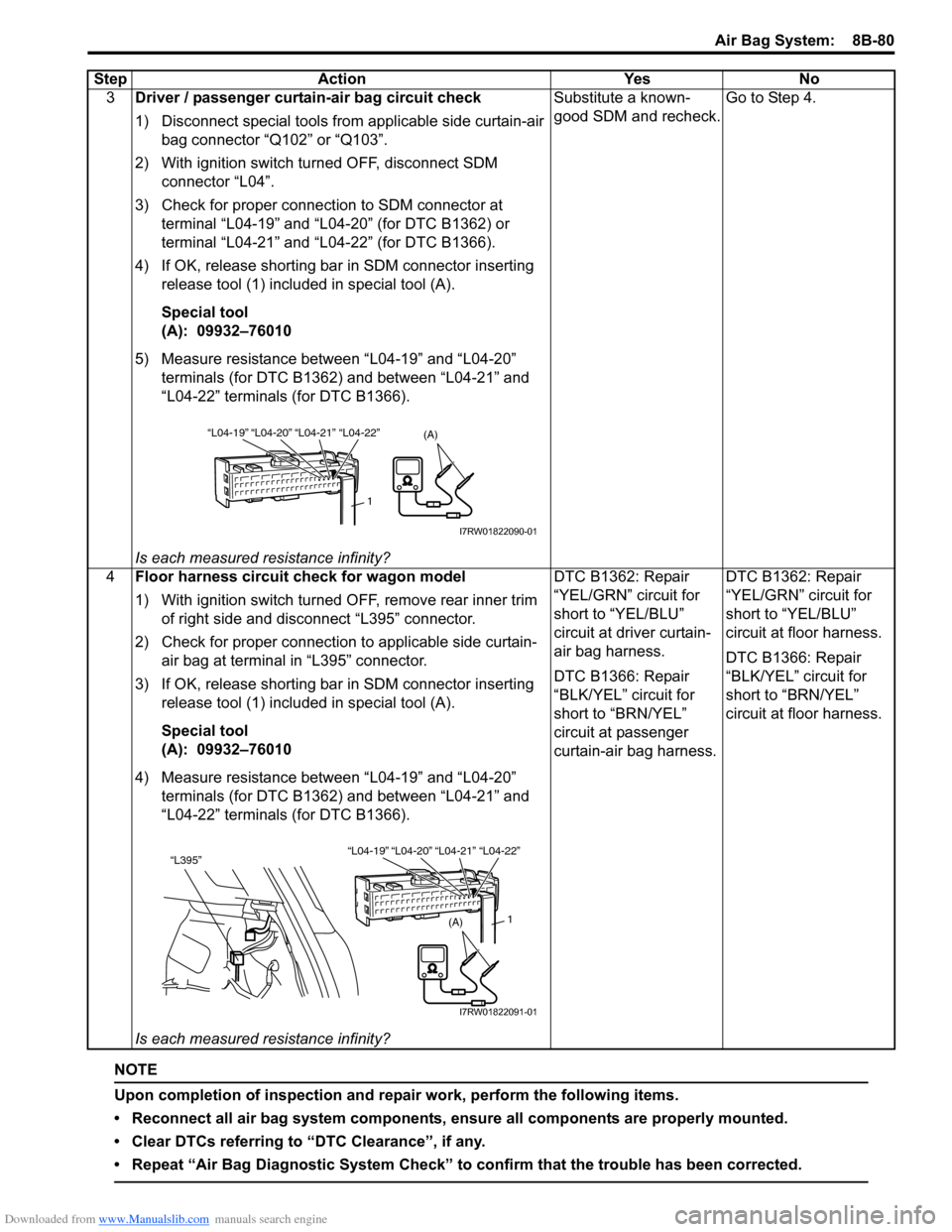
3Driver / passenger curtain-air bag circuit check
1) Disconnect special tools from applicable side curtain-air
bag connector “Q102” or “Q103”.
2) With ignition switch turned OFF, disconnect SDM
connector “L04”.
3) Check for proper connection to SDM connector at
terminal “L04-19” and “L04-20” (for DTC B1362) or
terminal “L04-21” and “L04-22” (for DTC B1366).
4) If OK, release shorting bar in SDM connector inserting
release tool (1) included in special tool (A).
Special tool
(A): 09932–76010
5) Measure resistance between “L04-19” and “L04-20”
terminals (for DTC B1362) and between “L04-21” and
“L04-22” terminals (for DTC B1366).
Is each measured resistance infinity?Substitute a known-
good SDM and recheck.Go to Step 4.
4Floor harness circuit check for wagon model
1) With ignition switch turned OFF, remove rear inner trim
of right side and disconnect “L395” connector.
2) Check for proper connection to applicable side curtain-
air bag at terminal in “L395” connector.
3) If OK, release shorting bar in SDM connector inserting
release tool (1) included in special tool (A).
Special tool
(A): 09932–76010
4) Measure resistance between “L04-19” and “L04-20”
terminals (for DTC B1362) and between “L04-21” and
“L04-22” terminals (for DTC B1366).
Is each measured resistance infinity?DTC B1362: Repair
“YEL/GRN” circuit for
short to “YEL/BLU”
circuit at driver curtain-
air bag harness.
DTC B1366: Repair
“BLK/YEL” circuit for
short to “BRN/YEL”
circuit at passenger
curtain-air bag harness.DTC B1362: Repair
“YEL/GRN” circuit for
short to “YEL/BLU”
circuit at floor harness.
DTC B1366: Repair
“BLK/YEL” circuit for
short to “BRN/YEL”
circuit at floor harness. Step Action Yes No
(A)“L04-20” “L04-21” “L04-19”“L04-22”
1
I7RW01822090-01
(A)
“L04-20” “L04-21” “L04-19”“L04-22”“L395”
1
I7RW01822091-01
Page 1120 of 1556
Downloaded from www.Manualslib.com manuals search engine 8B-81 Air Bag System:
DTC B1363 / B1367: Curtain-Air Bag Circuit Shorted to GroundS6RW0D8204064
DTC B1363: Driver Curtain-Air Bag Circuit Shorted to Ground
DTC B1367: Passenger Curtain-Air Bag Circuit Shorted to Ground
Wiring Diagram
Refer to “DTC B1361 / B1365: Curtain-Air Bag Circuit High Resistance”.
DTC Detecting Condition and Trouble Area
DTC TroubleshootingDTC detecting condition Trouble area
DTC B1363:
Driver curtain-air bag circuit has been shorted to ground
for more than 4 sec.
DTC B1367:
Passenger curtain-air bag circuit has been shorted to
ground for more than 4 sec.• Driver / passenger curtain-air bag circuit
•SDM
Step Action Yes No
1Was “Air Bag Diagnostic System Check Flow” performed?Go to Step 2. Go to “Air Bag
Diagnostic System
Check Flow”.
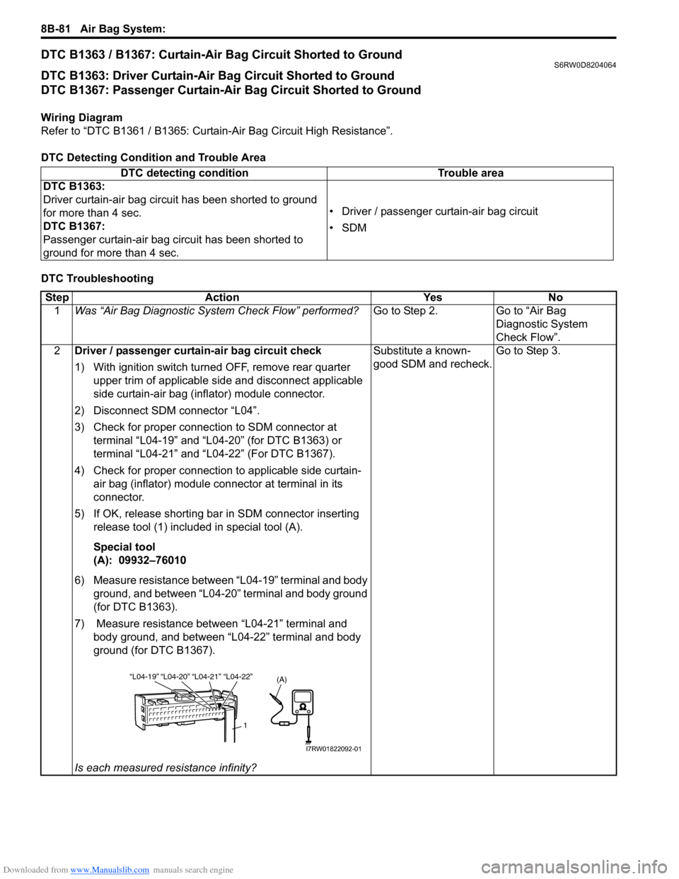
2Driver / passenger curtain-air bag circuit check
1) With ignition switch turned OFF, remove rear quarter
upper trim of applicable side and disconnect applicable
side curtain-air bag (inflator) module connector.
2) Disconnect SDM connector “L04”.
3) Check for proper connection to SDM connector at
terminal “L04-19” and “L04-20” (for DTC B1363) or
terminal “L04-21” and “L04-22” (For DTC B1367).
4) Check for proper connection to applicable side curtain-
air bag (inflator) module connector at terminal in its
connector.
5) If OK, release shorting bar in SDM connector inserting
release tool (1) included in special tool (A).
Special tool
(A): 09932–76010
6) Measure resistance between “L04-19” terminal and body
ground, and between “L04-20” terminal and body ground
(for DTC B1363).
7) Measure resistance between “L04-21” terminal and
body ground, and between “L04-22” terminal and body
ground (for DTC B1367).
Is each measured resistance infinity?Substitute a known-
good SDM and recheck.Go to Step 3.
“L04-20” “L04-21” “L04-19”“L04-22”
1
(A)
I7RW01822092-01
Page 1121 of 1556
Downloaded from www.Manualslib.com manuals search engine Air Bag System: 8B-82
NOTE
Upon completion of inspection and repair work, perform the following items.
• Reconnect all air bag system components, ensure all components are properly mounted.
• Clear DTCs referring to “DTC Clearance”, if any.
• Repeat “Air Bag Diagnostic System Check” to confirm that the trouble has been corrected.
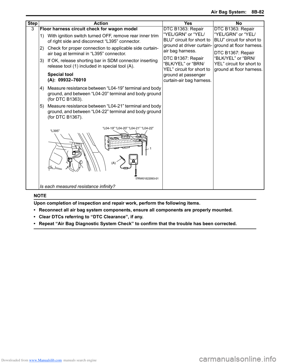
3Floor harness circuit check for wagon model
1) With ignition switch turned OFF, remove rear inner trim
of right side and disconnect “L395” connector.
2) Check for proper connection to applicable side curtain-
air bag at terminal in “L395” connector.
3) If OK, release shorting bar in SDM connector inserting
release tool (1) included in special tool (A).
Special tool
(A): 09932–76010
4) Measure resistance between “L04-19” terminal and body
ground, and between “L04-20” terminal and body ground
(for DTC B1363).
5) Measure resistance between “L04-21” terminal and body
ground, and between “L04-22” terminal and body ground
(for DTC B1367).
Is each measured resistance infinity?DTC B1363: Repair
“YEL/GRN” or “YEL/
BLU” circuit for short to
ground at driver curtain-
air bag harness.
DTC B1367: Repair
“BLK/YEL” or “BRN/
YEL” circuit for short to
ground at passenger
curtain-air bag harness.DTC B1363: Repair
“YEL/GRN” or “YEL/
BLU” circuit for short to
ground at floor harness.
DTC B1367: Repair
“BLK/YEL” or “BRN/
YEL” circuit for short to
ground at floor harness. Step Action Yes No
“L04-20” “L04-21” “L04-19”“L04-22”“L395”
1
(A)
I7RW01822093-01
Page 1122 of 1556
Downloaded from www.Manualslib.com manuals search engine 8B-83 Air Bag System:
DTC B1364 / B1368: Curtain-Air Bag Circuit Shorted to Power SupplyS6RW0D8204065
DTC B1364: Driver Curtain-Air Bag Circuit Shorted to Power Supply
DTC B1368: Passenger Curtain-Air Bag Circuit Shorted to Power Supply
Wiring Diagram
Refer to “DTC B1361 / B1365: Curtain-Air Bag Circuit High Resistance”.
DTC Detecting Condition and Trouble Area
DTC TroubleshootingDTC detecting condition Trouble area
DTC B1364:
Driver curtain-air bag circuit has been shorted to power
circuit for more than 4 sec.
DTC B1368:
Passenger curtain-air bag circuit has been shorted to
power circuit for more than 4 sec.• Driver / passenger curtain-air bag circuit
•SDM
Step Action Yes No
1Was “Air Bag Diagnostic System Check Flow” performed?Go to Step 2. Go to “Air Bag
Diagnostic System
Check Flow”.
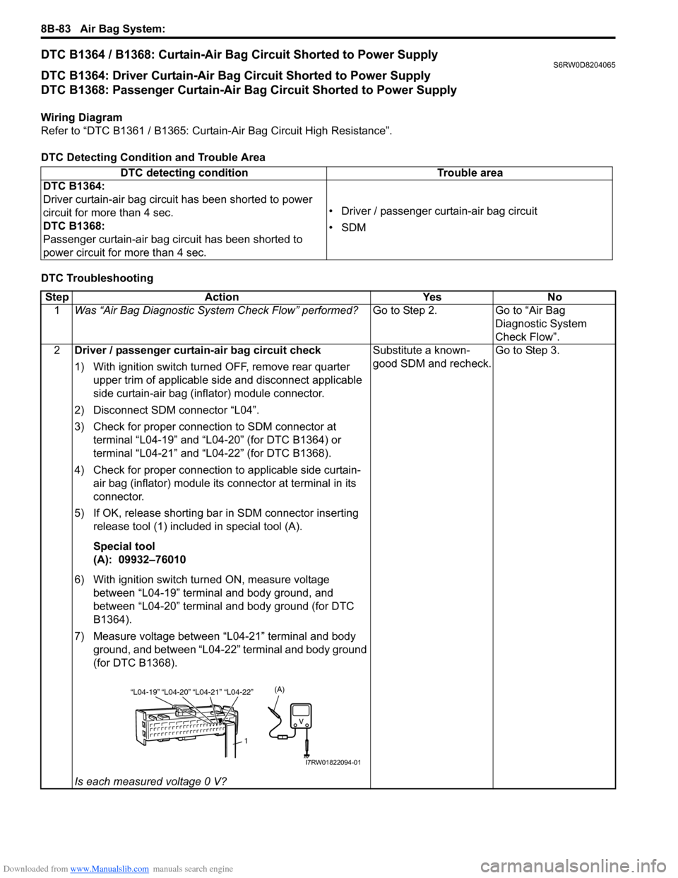
2Driver / passenger curtain-air bag circuit check
1) With ignition switch turned OFF, remove rear quarter
upper trim of applicable side and disconnect applicable
side curtain-air bag (inflator) module connector.
2) Disconnect SDM connector “L04”.
3) Check for proper connection to SDM connector at
terminal “L04-19” and “L04-20” (for DTC B1364) or
terminal “L04-21” and “L04-22” (for DTC B1368).
4) Check for proper connection to applicable side curtain-
air bag (inflator) module its connector at terminal in its
connector.
5) If OK, release shorting bar in SDM connector inserting
release tool (1) included in special tool (A).
Special tool
(A): 09932–76010
6) With ignition switch turned ON, measure voltage
between “L04-19” terminal and body ground, and
between “L04-20” terminal and body ground (for DTC
B1364).
7) Measure voltage between “L04-21” terminal and body
ground, and between “L04-22” terminal and body ground
(for DTC B1368).
Is each measured voltage 0 V?Substitute a known-
good SDM and recheck.Go to Step 3.
“L04-20” “L04-21” “L04-19”“L04-22”
1
(A)
I7RW01822094-01
Page 1123 of 1556
Downloaded from www.Manualslib.com manuals search engine Air Bag System: 8B-84
NOTE
Upon completion of inspection and repair work, perform the following items.
• Reconnect all air bag system components, ensure all components are properly mounted.
• Clear DTCs referring to “DTC Clearance”, if any.
• Repeat “Air Bag Diagnostic System Check” to confirm that the trouble has been corrected.
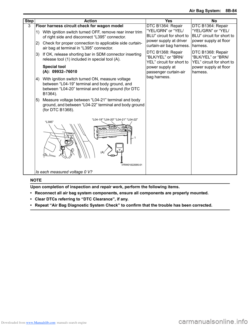
3Floor harness circuit check for wagon model
1) With ignition switch turned OFF, remove rear inner trim
of right side and disconnect “L395” connector.
2) Check for proper connection to applicable side curtain-
air bag at terminal in “L395” connector.
3) If OK, release shorting bar in SDM connector inserting
release tool (1) included in special tool (A).
Special tool
(A): 09932–76010
4) With ignition switch turned ON, measure voltage
between “L04-19” terminal and body ground, and
between “L04-20” terminal and body ground (for DTC
B1364).
5) Measure voltage between “L04-21” terminal and body
ground, and between “L04-22” terminal and body ground
(for DTC B1368).
Is each measured voltage 0 V?DTC B1364: Repair
“YEL/GRN” or “YEL/
BLU” circuit for short to
power supply at driver
curtain-air bag harness.
DTC B1368: Repair
“BLK/YEL” or “BRN/
YEL” circuit for short to
power supply at
passenger curtain-air
bag harness.DTC B1364: Repair
“YEL/GRN” or “YEL/
BLU” circuit for short to
power supply at floor
harness.
DTC B1368: Repair
“BLK/YEL” or “BRN/
YEL” circuit for short to
power supply at floor
harness. Step Action Yes No
“L04-20” “L04-21” “L04-19”“L04-22”“L395”
1
(A)
I7RW01822095-01
Page 1131 of 1556
Downloaded from www.Manualslib.com manuals search engine Air Bag System: 8B-92
– Check connector or lead wire of SDM for scorching,
melting or damage.
– Check SDM connector and terminals for tightness.
– Check if SDM sets a DTC and is judged as
malfunctioning according to the diagnostic flow.
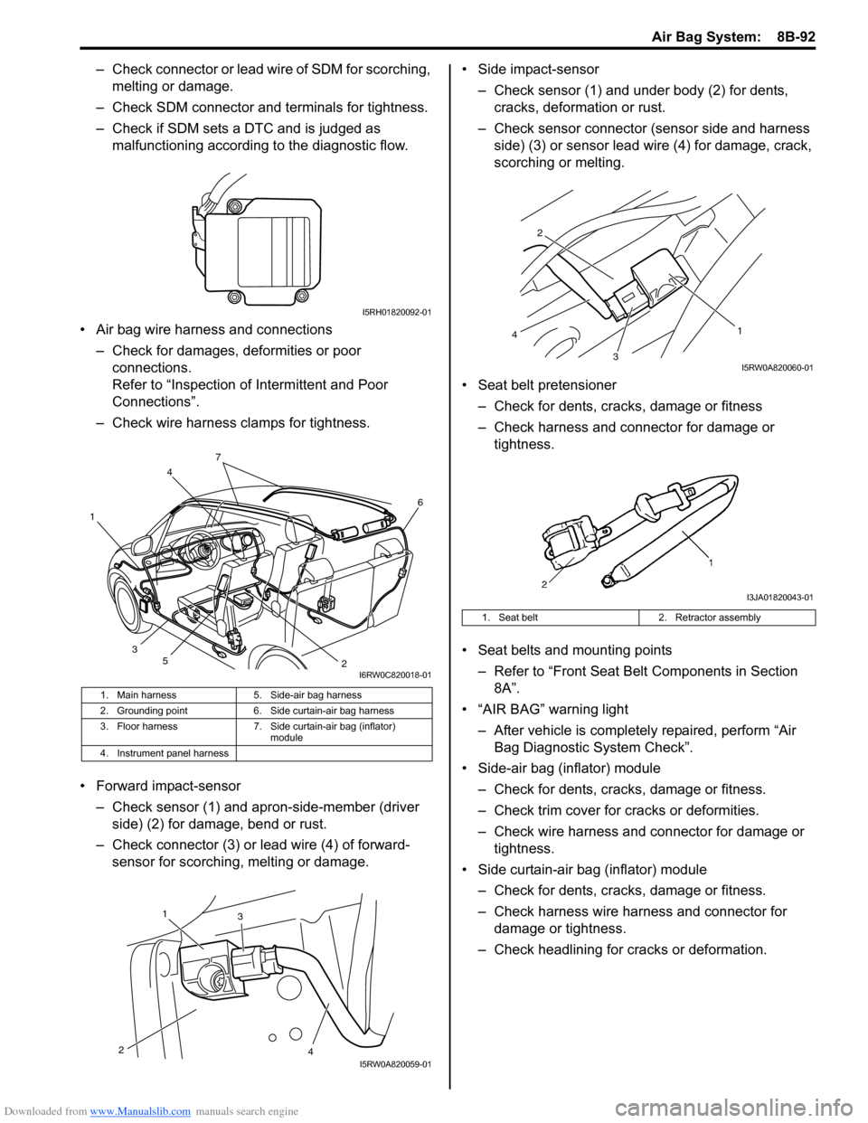
• Air bag wire harness and connections
– Check for damages, deformities or poor
connections.
Refer to “Inspection of Intermittent and Poor
Connections”.
– Check wire harness clamps for tightness.
• Forward impact-sensor
– Check sensor (1) and apron-side-member (driver
side) (2) for damage, bend or rust.
– Check connector (3) or lead wire (4) of forward-
sensor for scorching, melting or damage.• Side impact-sensor
– Check sensor (1) and under body (2) for dents,
cracks, deformation or rust.
– Check sensor connector (sensor side and harness
side) (3) or sensor lead wire (4) for damage, crack,
scorching or melting.
• Seat belt pretensioner
– Check for dents, cracks, damage or fitness
– Check harness and connector for damage or
tightness.
• Seat belts and mounting points
– Refer to “Front Seat Belt Components in Section
8A”.
• “AIR BAG” warning light
– After vehicle is completely repaired, perform “Air
Bag Diagnostic System Check”.
• Side-air bag (inflator) module
– Check for dents, cracks, damage or fitness.
– Check trim cover for cracks or deformities.
– Check wire harness and connector for damage or
tightness.
• Side curtain-air bag (inflator) module
– Check for dents, cracks, damage or fitness.
– Check harness wire harness and connector for
damage or tightness.
– Check headlining for cracks or deformation.
1. Main harness 5. Side-air bag harness
2. Grounding point 6. Side curtain-air bag harness
3. Floor harness 7. Side curtain-air bag (inflator)
module
4. Instrument panel harness
I5RH01820092-01
4
1
26
3
5
7
I6RW0C820018-01
1
23
4I5RW0A820059-01
1. Seat belt 2. Retractor assembly
3 2
1
4
I5RW0A820060-01
I3JA01820043-01
Page 1146 of 1556
Downloaded from www.Manualslib.com manuals search engine 8B-107 Air Bag System:
7) Install passenger air bag (inflator) module referring
to “Passenger Air Bag (Inflator) Module Removal
and Installation”.
8) Enabling air bag system referring to “Enabling Air
Bag System”.
9) Confirm that there is no DTC detected to SDM with
ignition switch turned ON.
Air Bag (Inflator) Module and Seat Belt
Pretensioner Disposal
S6RW0D8206018
WARNING!
Failure to follow proper air bag (inflator)
module and seat belt pretensioner disposal
procedures can result in air bag deployment
and pretensioner activation which may cause
personal injury. Do not dispose of live
(undeployed) air bag (inflator) modules and
seat belt pretensioners. Because undeployed
air bag (inflator) module / inactivated seat
belt pretensioner must not be disposed of
through normal refuse channels. Undeployed
air bag (inflator) module and inactivated seat
belt pretensioner contain substances that
can cause severe illness or personal injury if
sealed container is damaged during disposal.
Air bag (inflator) module / seat belt pretensioner can be
deployed / activated inside or outside of vehicle.
Deployment / Activation method used depends upon
final disposition of vehicle. Review the following
instructions in order to determine which will work best in
a given situation.
Deployment / Activation Outside of Vehicle: When you
intend to return the vehicle to service, deploy the air bag
(inflator) module(s) and/or activate seat belt
pretensioner(s) outside of the vehicle.
Deployment / Activation Inside of Vehicle: When the
vehicle will be destroyed, or salvaged for component
parts, deploy the air bag module(s) and/or activate seat
belt pretensioner(s) installed on vehicle.
WARNING!
The following precautions must be observed
for this work. Failure to observe any of them
may result in personal injury.
• Procedure should be followed strictly as
described here.
• Be sure to read “Precautions on Service
and Diagnosis of Air Bag System”
beforehand.
• To avoid accidental deployment /
activation, this work should be performed
by no more than one person.
• Since smoke is produced when air bag
(inflator) module is deployed and
pretensioner is activated, select well-
ventilated area.
• Air bag (inflator) module and seat belt
pretensioner will immediately deploy /
activate when 12 volts vehicle battery is
connected to it. Wear safety glasses
throughout this entire deployment /
activation and disposal procedure.
• Wear suitable ear protection when
deploying air bag (inflator) module /
activating seat belt pretensioner. Also,
advise those who are in area close to
deployment / activation site to wear
suitable ear protection.
• Do not deploy / activate two or more air
bag system components (air bag (inflator)
modules and seat belt pretensioners) at
the same time.
• Never connect deployment harness to any
12 volts vehicle battery before connecting
deployment harness to air bag (inflator)
module and seat belt pretensioner.
Deployment harness shall remain shorted
and not be connected to 12 volts vehicle
battery till you are ready to deploy air bag
(inflator) module or activate seat belt
pretensioner.
Page 1353 of 1556
Downloaded from www.Manualslib.com manuals search engine Instrumentation / Driver Info. / Horn: 9C-1
Body, Cab and Accessories
Instrumentation / Driver Info. / Horn
Precautions
Precautions in Diagnosing Troubles for Combination MeterS6RW0D9300001
Combination meter uses signals (information) from each control module by CAN communication to control
speedometer, tachometer, fuel meter, engine coolant temp meter, warning light and indicator light (other than air bag
warning light, EPS warning light, headlight leveling warning light (if equipped), rear fog light indicator light (if
equipped), high beam indicator light and turn signal indicator light). Therefor, check that no DTC is detected in each
module before performing combination meter symptom diagnosis. If any DTC is detected, correct trouble indicated by
that DTC troubleshooting first.
General Description
CAN Communication System DescriptionS6RW0D9301001
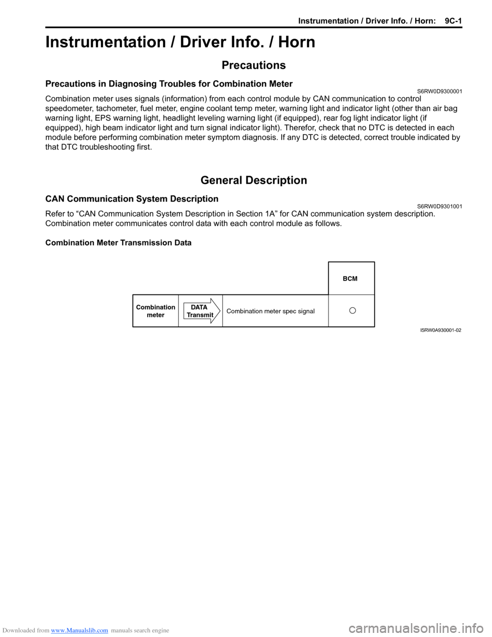
Refer to “CAN Communication System Description in Section 1A” for CAN communication system description.
Combination meter communicates control data with each control module as follows.
Combination Meter Transmission Data
BCM
Combination
meterDATA
TransmitCombination meter spec signal
I5RW0A930001-02