2006 SUZUKI SX4 air condition
[x] Cancel search: air conditionPage 1389 of 1556
Downloaded from www.Manualslib.com manuals search engine Glass / Windows / Mirrors: 9E-4
Inspection of Pinching Prevention Function (Pinching Prevention Function Model)S6RW0D9504032
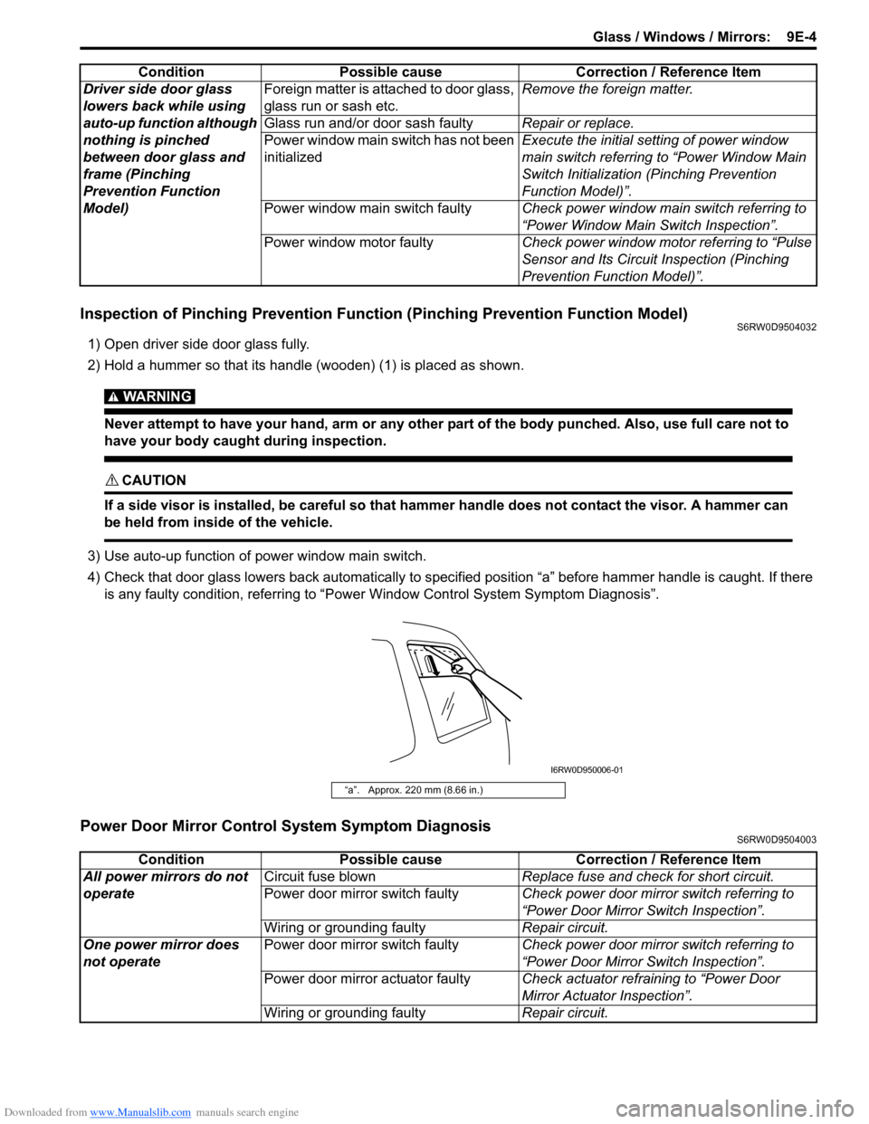
1) Open driver side door glass fully.
2) Hold a hummer so that its handle (wooden) (1) is placed as shown.
WARNING!
Never attempt to have your hand, arm or any other part of the body punched. Also, use full care not to
have your body caught during inspection.
CAUTION!
If a side visor is installed, be careful so that hammer handle does not contact the visor. A hammer can
be held from inside of the vehicle.
3) Use auto-up function of power window main switch.
4) Check that door glass lowers back automatically to specified position “a” before hammer handle is caught. If there
is any faulty condition, referring to “Power Window Control System Symptom Diagnosis”.
Power Door Mirror Control System Symptom DiagnosisS6RW0D9504003
Driver side door glass
lowers back while using
auto-up function although
nothing is pinched
between door glass and
frame (Pinching
Prevention Function
Model)Foreign matter is attached to door glass,
glass run or sash etc.Remove the foreign matter.
Glass run and/or door sash faultyRepair or replace.
Power window main switch has not been
initializedExecute the initial setting of power window
main switch referring to “Power Window Main
Switch Initialization (Pinching Prevention
Function Model)”.
Power window main switch faultyCheck power window main switch referring to
“Power Window Main Switch Inspection”.
Power window motor faultyCheck power window motor referring to “Pulse
Sensor and Its Circuit Inspection (Pinching
Prevention Function Model)”. Condition Possible cause Correction / Reference Item
“a”. Approx. 220 mm (8.66 in.)
I6RW0D950006-01
Condition Possible cause Correction / Reference Item
All power mirrors do not
operateCircuit fuse blownReplace fuse and check for short circuit.
Power door mirror switch faultyCheck power door mirror switch referring to
“Power Door Mirror Switch Inspection”.
Wiring or grounding faultyRepair circuit.
One power mirror does
not operatePower door mirror switch faultyCheck power door mirror switch referring to
“Power Door Mirror Switch Inspection”.
Power door mirror actuator faultyCheck actuator refraining to “Power Door
Mirror Actuator Inspection”.
Wiring or grounding faultyRepair circuit.
Page 1390 of 1556
Downloaded from www.Manualslib.com manuals search engine 9E-5 Glass / Windows / Mirrors:
Door Mirror Heater Symptom Diagnosis (If Equipped)S6RW0D9504004
NOTE
• Use of SUZUKI scan tool makes it easy to check whether a faulty condition is on the input side or
output side of BCM. For checking procedure, refer to “Diagnosis Using Output Test Function of
SUZUKI Scan Tool” under “Scan Tool Data in Section 10B”.
• Check each part in the order from the top of the following list.
Repair Instructions
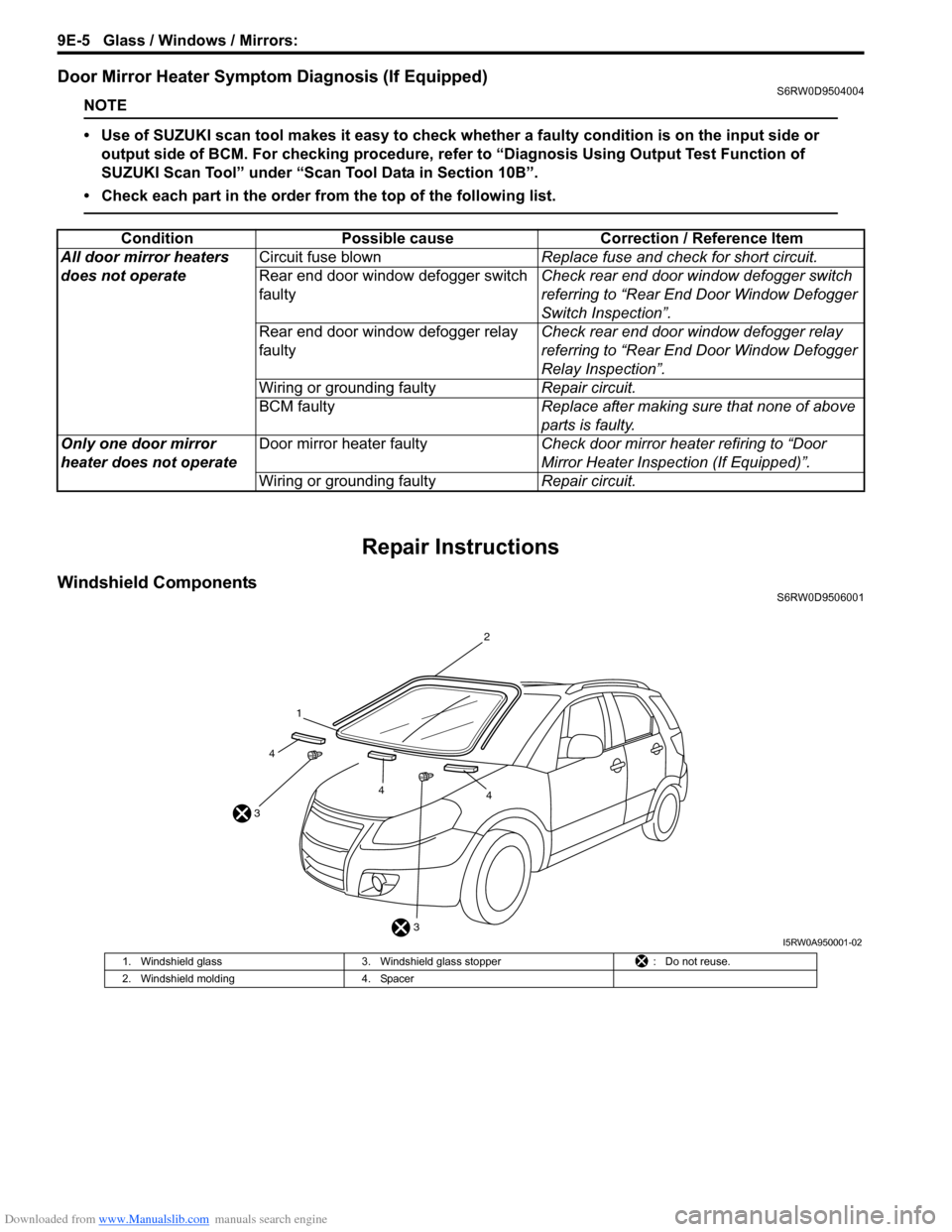
Windshield ComponentsS6RW0D9506001
Condition Possible cause Correction / Reference Item
All door mirror heaters
does not operateCircuit fuse blownReplace fuse and check for short circuit.
Rear end door window defogger switch
faultyCheck rear end door window defogger switch
referring to “Rear End Door Window Defogger
Switch Inspection”.
Rear end door window defogger relay
faultyCheck rear end door window defogger relay
referring to “Rear End Door Window Defogger
Relay Inspection”.
Wiring or grounding faultyRepair circuit.
BCM faultyReplace after making sure that none of above
parts is faulty.
Only one door mirror
heater does not operateDoor mirror heater faultyCheck door mirror heater refiring to “Door
Mirror Heater Inspection (If Equipped)”.
Wiring or grounding faultyRepair circuit.
3 31
2
44
4
I5RW0A950001-02
1. Windshield glass 3. Windshield glass stopper : Do not reuse.
2. Windshield molding 4. Spacer
Page 1414 of 1556
Downloaded from www.Manualslib.com manuals search engine 9F-3 Security and Locks:
Diagnostic Information and Procedures
Power Door Lock System Symptom Diagnosis (If Equipped)S6RW0D9604001
NOTE
• Use of SUZUKI scan tool makes it easy to check whether a faulty condition is on the input side or
output side of BCM. For checking procedure, refer to “Diagnosis Using Output Test Function of
SUZUKI Scan Tool” under “Scan Tool Data in Section 10B”.
• Check each part in the order from the top of the following list.
Power Door Lock System Operation Inspection (If Equipped)S6RW0D9604002
1) Check the following operation:
a) Turn the driver side key cylinder is turned LOCK once, check all doors lock.
b) Turn the driver side door key cylinder is turned UNLOCK position with door key twice, check all doors unlock.
c) With all doors unlocked, insert key in key cylinder of driver side door and turn it to lock side, turn it again to lock
side within 3 seconds and check that no door can be opened even when door lock knob is moved to unlock
side (dead lock function, if equipped).
If malfunction is found, go to “Power Door Lock System Symptom Diagnosis (If Equipped)”. Condition Possible cause Correction / Reference Item
All door can not be locked
/ unlocked by all of
switchesCircuit fuse blownReplace fuse and check for short circuit.
Wiring or grounding faultyRepair circuit.
BCM faultyReplace after making sure that none of above
parts is faulty.
All door can not be locked
/ unlocked by only power
door lock switchCircuit fuse blownReplace fuse and check for short circuit.
Power door lock switch faultyCheck power door lock switch referring to
“Power Door Lock Switch Inspection (If
Equipped)”.
Wiring harness connected to power door
lock switch faultyRepair.
Wiring or grounding faultyRepair circuit.
BCM faultyReplace after making sure that none of above
parts is faulty.
All door can not be locked
/ unlocked by only key
cylinder switchCircuit fuse blownReplace fuse and check for short circuit.
Key cylinder switch faultyCheck key cylinder switch referring to “Door
Key Cylinder Switch Inspection (If Equipped)”.
Wiring or grounding faultyRepair circuit.
BCM faultyReplace after making sure that none of above
parts is faulty.
Only one door can not be
locked / unlockedPower door lock actuator faultyCheck actuator referring to “Power Door Lock
Actuator Inspection (If Equipped)”.
Wiring harness connected to applicable
door lock actuator faultyRepair.
BCM faultyReplace after making sure that none of above
parts is faulty.
Page 1415 of 1556
Downloaded from www.Manualslib.com manuals search engine Security and Locks: 9F-4
Keyless Entry System Symptom Diagnosis (If Equipped)S6RW0D9604003
NOTE
• Confirm that power door lock system is in good condition before referring to the following possible
causes.
• Check each part in the order from the top of the following list.
Condition Possible cause Correction / Reference Item
All door can not be locked
/ unlocked by only
keyless entry transmitterTransmitter battery deadReplace battery referring to “Replacement of
Transmitter Battery (Other than Keyless Start
Model)”.
Door switch faultyCheck door switch referring to “Door Switch
(Front / Rear Door) Inspection in Section 9C”
and/or “Rear End Door Switch Inspection in
Section 9C”.
Transmitter faultyReplace transmitter.
Key reminder switch in ignition switch
faultyCheck ignition switch referring to “Ignition
Switch Inspection in Section 9C”.
Wiring or grounding faultyRepair circuit.
Keyless entry receiver faultyCheck keyless entry receiver referring to
“Keyless Entry Receiver and Its Circuit
Inspection (If Equipped)”.
BCM faultyReplace after making sure that none of above
parts is faulty.
Turn signal lights can not
be flashed when doors
are locked / unlocked by
keyless entry transmitterTurn signal and hazard warning relay
faultyCheck turn signal and hazard warning relay
referring to “Turn Signal and Hazard Warning
Relay Inspection in Section 9B”.
Wiring or grounding faultyRepair circuit.
BCM faultyReplace after making sure that none of above
parts is faulty.
Interior light does not
light when doors are
unlocked by keyless entry
transmitterWiring or grounding faultyRepair circuit.
BCM faultyReplace after making sure that none of above
parts is faulty.
Hazard warning lights do
not light when doors are
locked/unlocked by
keyless entry transmitterTurn signal and hazard warning relay
faultyCheck turn signal and hazard warning relay
referring to “Turn Signal and Hazard Warning
Relay Inspection in Section 9B”.
Wiring or grounding faultyRepair circuit.
BCM faultyReplace after making sure that none of above
parts is faulty.
Transmitter code can not
be programmed to BCMDoor switch faultyCheck door switch referring to “Door Switch
(Front / Rear Door) Inspection in Section 9C”
and/or “Rear End Door Switch Inspection in
Section 9C”.
Keyless entry receiver faultyCheck keyless entry receiver referring to
“Keyless Entry Receiver and Its Circuit
Inspection (If Equipped)”.
Key reminder switch in ignition switch
faultyCheck ignition switch referring to “Ignition
Switch Inspection in Section 9C”.
Wiring or grounding faultyRepair circuit.
BCM faultyReplace after making sure that none of above
parts is faulty.
Page 1416 of 1556
Downloaded from www.Manualslib.com manuals search engine 9F-5 Security and Locks:
Keyless Entry System Operation Inspection (If
Equipped)
S6RW0D9604004
NOTE
When performing the this inspection, make
sure to have any of the door once opened /
closed after the ignition key has been
removed from the ignition key cylinder.
1) Confirm that power door lock system operates
normally, refer to “Power Door Lock System
Operation Inspection (If Equipped)”.
2) All doors are closed and unlocked.
3) Check the following operation:
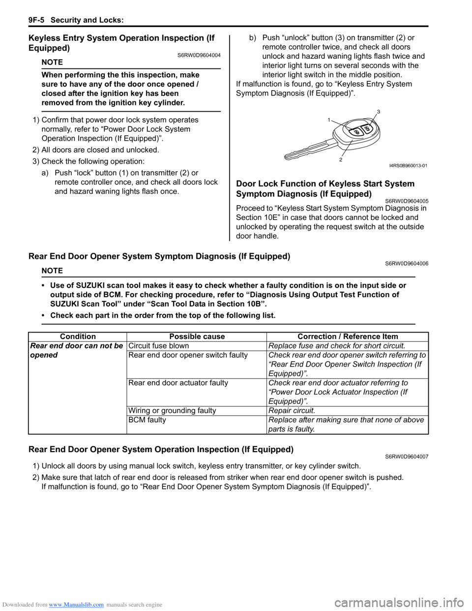
a) Push “lock” button (1) on transmitter (2) or
remote controller once, and check all doors lock
and hazard waning lights flash once.b) Push “unlock” button (3) on transmitter (2) or
remote controller twice, and check all doors
unlock and hazard waning lights flash twice and
interior light turns on several seconds with the
interior light switch in the middle position.
If malfunction is found, go to “Keyless Entry System
Symptom Diagnosis (If Equipped)”.
Door Lock Function of Keyless Start System
Symptom Diagnosis (If Equipped)
S6RW0D9604005
Proceed to “Keyless Start System Symptom Diagnosis in
Section 10E” in case that doors cannot be locked and
unlocked by operating the request switch at the outside
door handle.
Rear End Door Opener System Symptom Diagnosis (If Equipped)S6RW0D9604006
NOTE
• Use of SUZUKI scan tool makes it easy to check whether a faulty condition is on the input side or
output side of BCM. For checking procedure, refer to “Diagnosis Using Output Test Function of
SUZUKI Scan Tool” under “Scan Tool Data in Section 10B”.
• Check each part in the order from the top of the following list.
Rear End Door Opener System Operation Inspection (If Equipped)S6RW0D9604007
1) Unlock all doors by using manual lock switch, keyless entry transmitter, or key cylinder switch.
2) Make sure that latch of rear end door is released from striker when rear end door opener switch is pushed.
If malfunction is found, go to “Rear End Door Opener System Symptom Diagnosis (If Equipped)”.
1
3
2I4RS0B960013-01
Condition Possible cause Correction / Reference Item
Rear end door can not be
openedCircuit fuse blownReplace fuse and check for short circuit.
Rear end door opener switch faultyCheck rear end door opener switch referring to
“Rear End Door Opener Switch Inspection (If
Equipped)”.
Rear end door actuator faultyCheck rear end door actuator referring to
“Power Door Lock Actuator Inspection (If
Equipped)”.
Wiring or grounding faultyRepair circuit.
BCM faultyReplace after making sure that none of above
parts is faulty.
Page 1428 of 1556
Downloaded from www.Manualslib.com manuals search engine 9G-1 Seats:
Body, Cab and Accessories
Seats
Diagnostic Information and Procedures
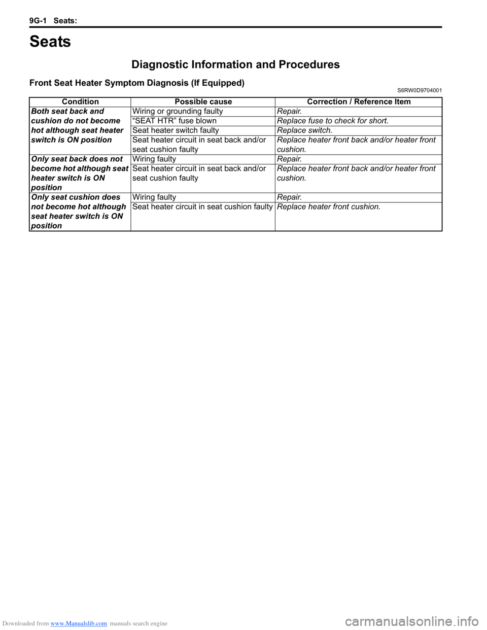
Front Seat Heater Symptom Diagnosis (If Equipped)S6RW0D9704001
Condition Possible cause Correction / Reference Item
Both seat back and
cushion do not become
hot although seat heater
switch is ON positionWiring or grounding faultyRepair.
“SEAT HTR” fuse blownReplace fuse to check for short.
Seat heater switch faultyReplace switch.
Seat heater circuit in seat back and/or
seat cushion faultyReplace heater front back and/or heater front
cushion.
Only seat back does not
become hot although seat
heater switch is ON
positionWiring faultyRepair.
Seat heater circuit in seat back and/or
seat cushion faultyReplace heater front back and/or heater front
cushion.
Only seat cushion does
not become hot although
seat heater switch is ON
positionWiring faultyRepair.
Seat heater circuit in seat cushion faultyReplace heater front cushion.
Page 1455 of 1556
Downloaded from www.Manualslib.com manuals search engine Paint / Coatings: 9L-1
Body, Cab and Accessories
Paint / Coatings
General Description
Anti-Corrosion Treatment ConstructionS6RW0D9C01001
WARNING!
Standard shop practices, particularly eye protection, should be followed during the performance of the
following operations to avoid personal injury.
As rust proof treatment, steel sheets are given corrosion resistance on the interior and/or exterior.
These corrosion resistance steel sheet materials are called one of two-side galvanized steel sheets.
It is for the sake of rust protection that these materials are selected and given a variety of treatments as described
blow.
• Steel sheets are treated with cathodic electro primer which is excellent in corrosion resistance.
• Rust proof wax coatings are applied to door and side sill insides where moisture is liable to stay.
• Vinyl coating is applied to body underside and wheel housing inside.
• Sealer is applied to door hem, engine compartment steel sheet-to-steel sheet joint, and the like portions to prevent
water penetration and resulting in rust occurrence.
In panel replacement or collision damage repair, leaving the relevant area untreated as it is in any operation which
does disturb the rust proof treatment will cause corrosion to that area. Therefore, it is the essential function of any
repair operation to correctly recoat the related surfaces of the relevant area.
All the metal panels are coated with metal conditioners and primer coating during vehicle production. Following the
repair and/or replacement parts installation, every accessible bare metal surface should be cleaned and coated with
rust proof primer. Perform this operation prior to the application of sealer and rust proof wax coating.
Sealer is applied to the specific joints of a vehicle during production. The sealer is intended to prevent dust from
entering the vehicle and serves also as an anticorrosion barrier. The sealer is applied to the door and hood hem areas
and between panels. Correct and reseal the originally sealed joints if damaged. Reseal the attaching joints of a new
replacement panel and reseal the hem area of a replacement door or hood.
Use a quality sealer to seal the flanged joints, overlap joints and seams. The sealer must have flexible characteristics
and paint ability after it’s applied to repair areas.
For the sealer to fill open joints, use caulking material. Select a sealer in conformance with the place and purpose of a
specific use. Observe the manufacturer’s label-stand instructions when using the sealer.
In many cases, repaired places require color painting. When this is required, follow the ordinary techniques specified
for the finish preparation, color painting and undercoating build-up.
Rust proof wax, a penetrative compound, is applied to the metal-to-metal surfaces (door and side sill insides) where it
is difficult to use ordinary undercoating material for coating. Therefore, when selecting the rust proof wax, it may be the
penetrative type.
During the undercoating (vinyl coating) application, care should be taken that sealer is not applied to the engine-
related parts and shock absorber mounting or rotating parts. Following the under coating, make sure that body drain
holes are kept open.
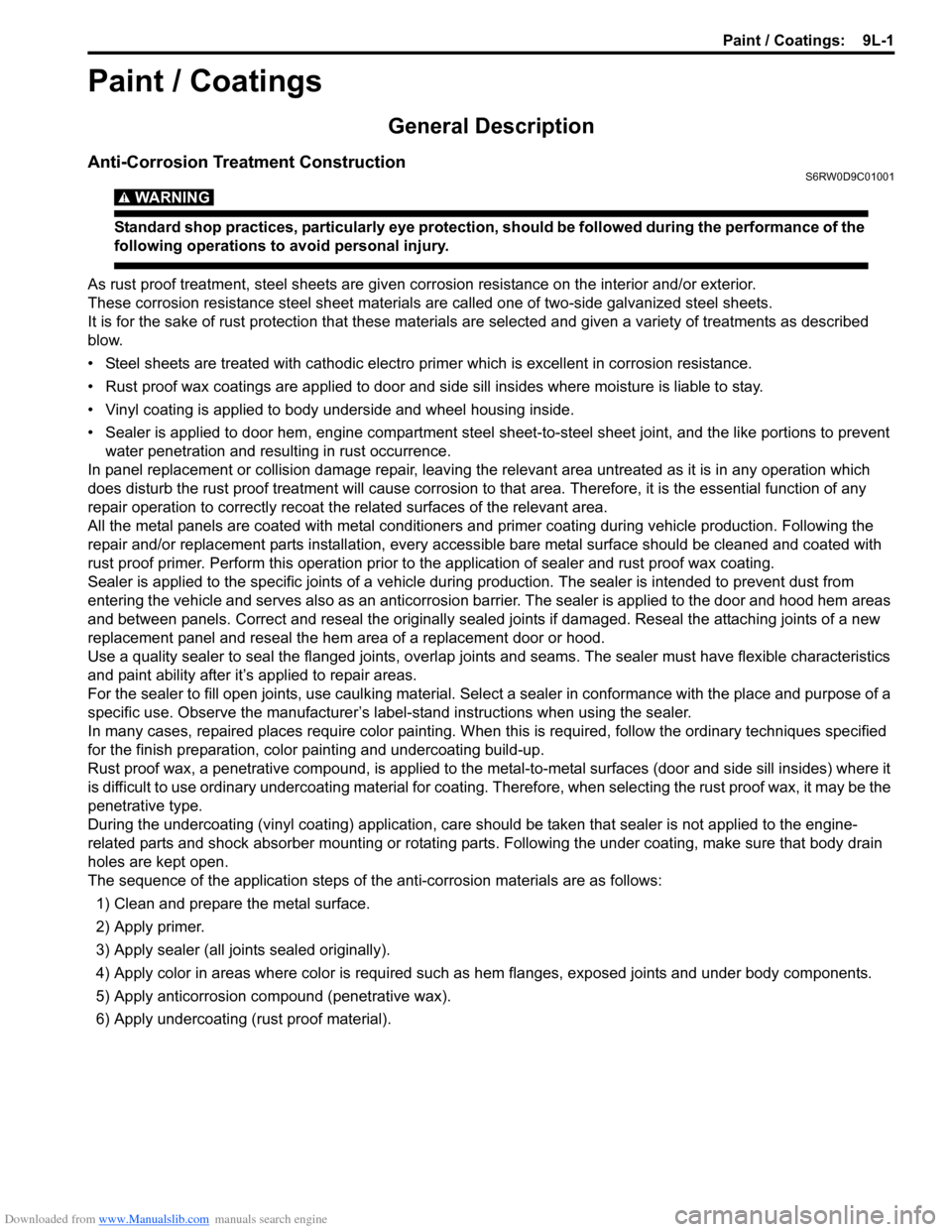
The sequence of the application steps of the anti-corrosion materials are as follows:
1) Clean and prepare the metal surface.
2) Apply primer.
3) Apply sealer (all joints sealed originally).
4) Apply color in areas where color is required such as hem flanges, exposed joints and under body components.
5) Apply anticorrosion compound (penetrative wax).
6) Apply undercoating (rust proof material).
Page 1456 of 1556
Downloaded from www.Manualslib.com manuals search engine 9L-2 Paint / Coatings:
Plastic Parts FinishingS6RW0D9C01002
Painting
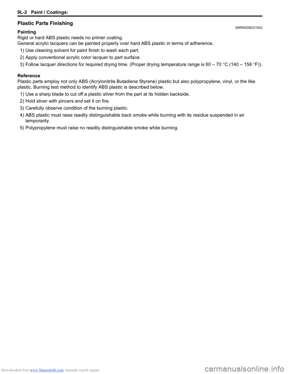
Rigid or hard ABS plastic needs no primer coating.
General acrylic lacquers can be painted properly over hard ABS plastic in terms of adherence.
1) Use cleaning solvent for paint finish to wash each part.
2) Apply conventional acrylic color lacquer to part surface.
3) Follow lacquer directions for required drying time. (Proper drying temperature range is 60 – 70 °C (140 – 158 °F)).
Reference
Plastic parts employ not only ABS (Acrylonitrile Butadiene Styrene) plastic but also polypropylene, vinyl, or the like
plastic. Burning test method to identify ABS plastic is described below.
1) Use a sharp blade to cut off a plastic sliver from the part at its hidden backside.
2) Hold sliver with pincers and set it on fire.
3) Carefully observe condition of the burning plastic.
4) ABS plastic must raise readily distinguishable back smoke while burning with its residue suspended in air
temporarily.
5) Polypropylene must raise no readily distinguishable smoke while burning.