2006 SUZUKI SX4 Lower bracket
[x] Cancel search: Lower bracketPage 918 of 1556

Downloaded from www.Manualslib.com manuals search engine 6C-38 Power Assisted Steering System:
2) Install steering gear case to vehicle, and then install
front suspension frame referring to “Front
Suspension Frame, Stabilizer Bar and/or Bushing
Removal and Installation in Section 2B”.
3) Install steering gear case to suspension frame (3) as
follows.
a) Set member bracket (2) to steering gear case
(1).
b) Install all steering gear case mounting bolts by
hand.
c) Tighten steering mounting bolts in numerical
order and specified torque.
Tightening torque
Steering gear case mounting bolt (a): 70 N·m (
7.0 kgf-m, 51.0 lb-ft)
4) Connect torque sensor connector and P/S motor
connector to steering gear case.
5) Be sure that steering wheel and brake discs (right &
left) are all straight-ahead position and then insert
steering lower shaft (5) into steering pinion shaft (3)
with matching marks (4).
6) Tighten steering shaft joint lower bolt (1) and upper
bolt (2) to specified torque (tighten lower side first
and then tighten upper side).
Tightening torque
Steering lower shaft assembly upper joint bolt
(a): 25 N·m (2.5 kgf-m, 18.5 lb-ft)
Steering lower shaft assembly lower joint bolt
(b): 25 N·m (2.5 kgf-m, 18.5 lb-ft)
7) Install steering joint cover.Steering Rack Boot InspectionS6RW0D6306007
Hoist vehicle.
Inspect each boot for tear. A torn boot allows entry of
dust and water which can cause wear to steering rack
and pinion to produce noise as well as rust to result in
malfunction of steering system.
Even if boot tear is small, replace with new one.
Also, check each boot for dent. If there is a dent, keep
boot in most compressed state for some seconds to
correct dent.
Boots should be visually inspected for any damage, dent
and tear during every periodical inspection at specified
intervals and whenever vehicle is hoisted for any other
purpose.
Tie-Rod / Rack Boot Removal and InstallationS6RW0D6306008
Removal
1) Remove steering gear case assembly referring to
“Steering Gear Case Assembly Removal and
Installation”.
2) Remove member bracket from steering gear case
assembly.
3) For ease of adjustment after installation, make
marking (1) of tie-rod end lock nut position of tie-rod
thread.
4) Loosen tie-rod end lock nut and remove tie-rod end.
5) Remove boot band (2) and clip (1).
6) Remove boot from tie-rod.I7RW01632009-01
5
4 1, (b)
3
2, (a)
1, (b)5
I5RW0A630020-01
I2RH01630012-01
I4RS0A630044-01
IYSQ01630034-01
Page 956 of 1556

Downloaded from www.Manualslib.com manuals search engine 7B-16 Air Conditioning System: Manual Type
Abnormal Noise from Tubing
Abnormal Noise from Condenser Assembly
Abnormal Noise from Crankshaft Pulley
Abnormal Noise from Tension Pulley
Abnormal Noise from A/C Evaporator
Abnormal Noise from Blower MotorCondition Possible cause Correction / Reference Item
A droning noise is heard
from inside of the vehicle,
but not particularly
noticeable in engine
compartmentFaulty tubing clampsReposition clamps or increase the number of
clamps.
Resonance caused by pulsation from
variations in refrigerant pressureAttach a silencer to tubing, or modify its
position and length.
Condition Possible cause Correction / Reference Item
Considerable vibration in
condenser assemblyResonance from condenser assembly
bracket and bodyFirmly insert a silencer between condenser
assembly bracket and body.
Condition Possible cause Correction / Reference Item
A large rattling noise is
heard at idle or sudden
accelerationLoosen crankshaft pulley boltRetighten bolt.
Condition Possible cause Correction / Reference Item
Clattering noise is heard
from pulleyWorn or damaged bearingReplace tension pulley.
Pulley cranks upon
contactCracked or loose bracketReplace or retighten bracket.
Condition Possible cause Correction / Reference Item
Whistling sound is heard
from A/C evaporatorDepending on the combination of the
interior / exterior temperatures, engine
rpm and refrigerant pressure, the
refrigerant flowing out of the expansion
valve may, under certain conditions,
make a whistling soundAt times, slightly decreasing refrigerant volume
may stop this noise.
Inspect expansion valve and replace if faulty.
Condition Possible cause Correction / Reference Item
Blower motor emits a
chirping sound in
proportion to its speed of
rotationWorn or damaged motor brushes or
commutatorReplace blower motor.
Fluttering noise or large
droning noise is heard
from blower motorLeaves or other debris introduced from
fresh air inlet to blower motorRemove debris and make sure that the screen
at fresh air inlet is intact.
Page 1133 of 1556
Downloaded from www.Manualslib.com manuals search engine Air Bag System: 8B-94
5) Install driver and passenger side front pillar lower
trim.
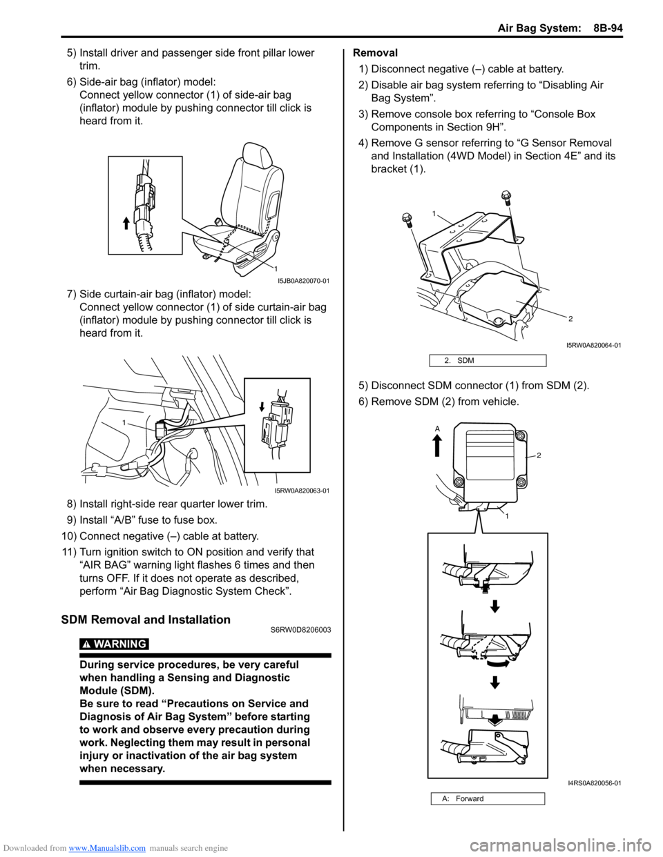
6) Side-air bag (inflator) model:
Connect yellow connector (1) of side-air bag
(inflator) module by pushing connector till click is
heard from it.
7) Side curtain-air bag (inflator) model:
Connect yellow connector (1) of side curtain-air bag
(inflator) module by pushing connector till click is
heard from it.
8) Install right-side rear quarter lower trim.
9) Install “A/B” fuse to fuse box.
10) Connect negative (–) cable at battery.
11) Turn ignition switch to ON position and verify that
“AIR BAG” warning light flashes 6 times and then
turns OFF. If it does not operate as described,
perform “Air Bag Diagnostic System Check”.
SDM Removal and InstallationS6RW0D8206003
WARNING!
During service procedures, be very careful
when handling a Sensing and Diagnostic
Module (SDM).
Be sure to read “Precautions on Service and
Diagnosis of Air Bag System” before starting
to work and observe every precaution during
work. Neglecting them may result in personal
injury or inactivation of the air bag system
when necessary.
Removal
1) Disconnect negative (–) cable at battery.
2) Disable air bag system referring to “Disabling Air
Bag System”.
3) Remove console box referring to “Console Box
Components in Section 9H”.
4) Remove G sensor referring to “G Sensor Removal
and Installation (4WD Model) in Section 4E” and its
bracket (1).
5) Disconnect SDM connector (1) from SDM (2).
6) Remove SDM (2) from vehicle.
1
I5JB0A820070-01
1
I5RW0A820063-01
2. SDM
A: Forward
1
2
I5RW0A820064-01
2
1
A
I4RS0A820056-01
Page 1144 of 1556
Downloaded from www.Manualslib.com manuals search engine 8B-105 Air Bag System:
Side Impact-Sensor Removal and InstallationS6RW0D8206024
WARNING!
During service procedures, be very careful
when handling a sensor.
• Never strike or jar a sensor.
• A sensor bolt must be carefully torqued to
assure proper operation. Under loose
connection, it could cause improper
operation of the air bag system.
Removal
1) Disconnect negative (–) cable at battery.
2) Disable air bag system. Refer to “Disabling Air Bag
System”.
3) Remove center pillar lower trim.
4) Turn up floor carpet at front seat side.
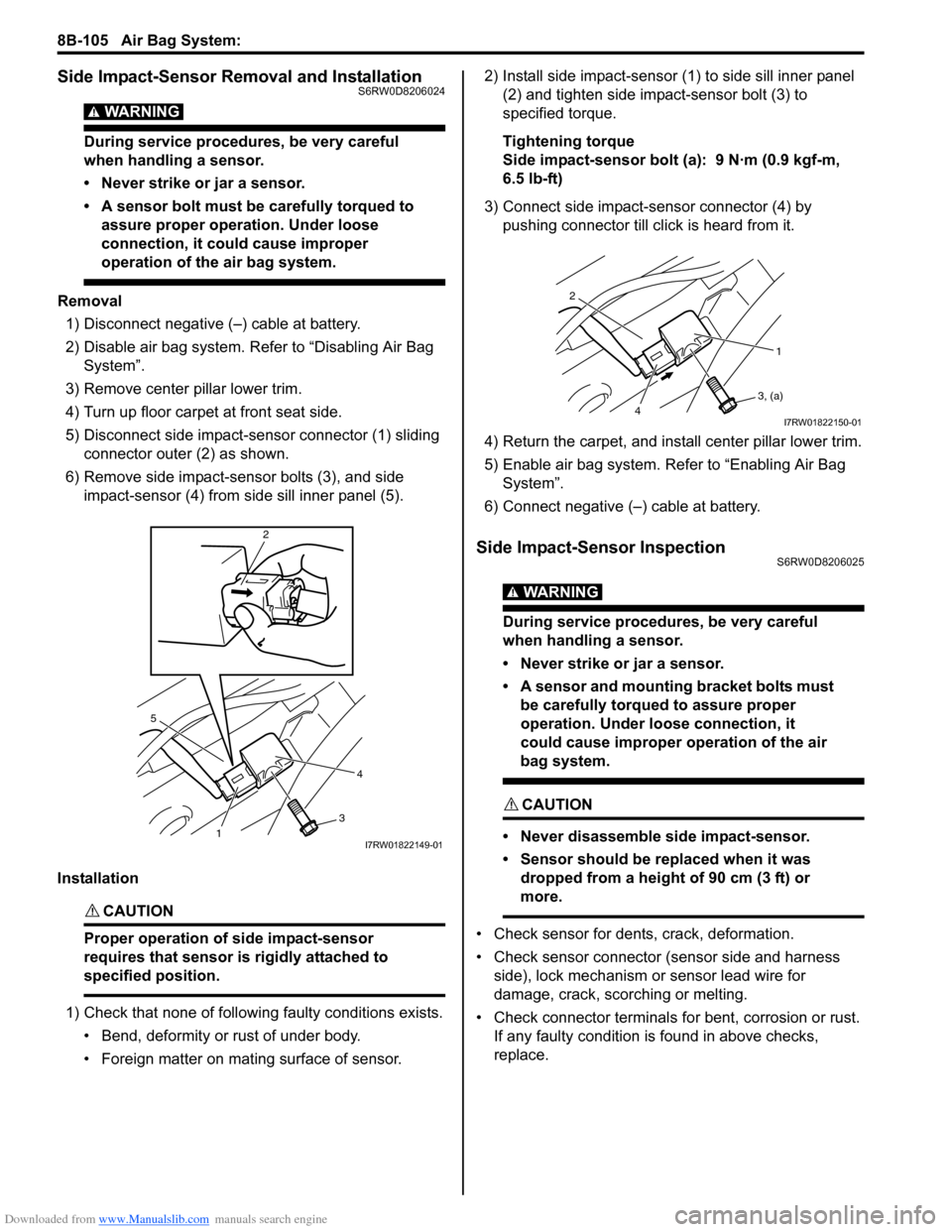
5) Disconnect side impact-sensor connector (1) sliding
connector outer (2) as shown.
6) Remove side impact-sensor bolts (3), and side
impact-sensor (4) from side sill inner panel (5).
Installation
CAUTION!
Proper operation of side impact-sensor
requires that sensor is rigidly attached to
specified position.
1) Check that none of following faulty conditions exists.
• Bend, deformity or rust of under body.
• Foreign matter on mating surface of sensor.2) Install side impact-sensor (1) to side sill inner panel
(2) and tighten side impact-sensor bolt (3) to
specified torque.
Tightening torque
Side impact-sensor bolt (a): 9 N·m (0.9 kgf-m,
6.5 lb-ft)
3) Connect side impact-sensor connector (4) by
pushing connector till click is heard from it.
4) Return the carpet, and install center pillar lower trim.
5) Enable air bag system. Refer to “Enabling Air Bag
System”.
6) Connect negative (–) cable at battery.
Side Impact-Sensor InspectionS6RW0D8206025
WARNING!
During service procedures, be very careful
when handling a sensor.
• Never strike or jar a sensor.
• A sensor and mounting bracket bolts must
be carefully torqued to assure proper
operation. Under loose connection, it
could cause improper operation of the air
bag system.
CAUTION!
• Never disassemble side impact-sensor.
• Sensor should be replaced when it was
dropped from a height of 90 cm (3 ft) or
more.
• Check sensor for dents, crack, deformation.
• Check sensor connector (sensor side and harness
side), lock mechanism or sensor lead wire for
damage, crack, scorching or melting.
• Check connector terminals for bent, corrosion or rust.
If any faulty condition is found in above checks,
replace.
5
4
3
2
1I7RW01822149-01
2
1
3, (a)
4I7RW01822150-01
Page 1348 of 1556
Downloaded from www.Manualslib.com manuals search engine 9B-29 Lighting Systems:
Height Sensor Removal and Installation (If
Equipped)
S6RW0D9206027
Removal
CAUTION!
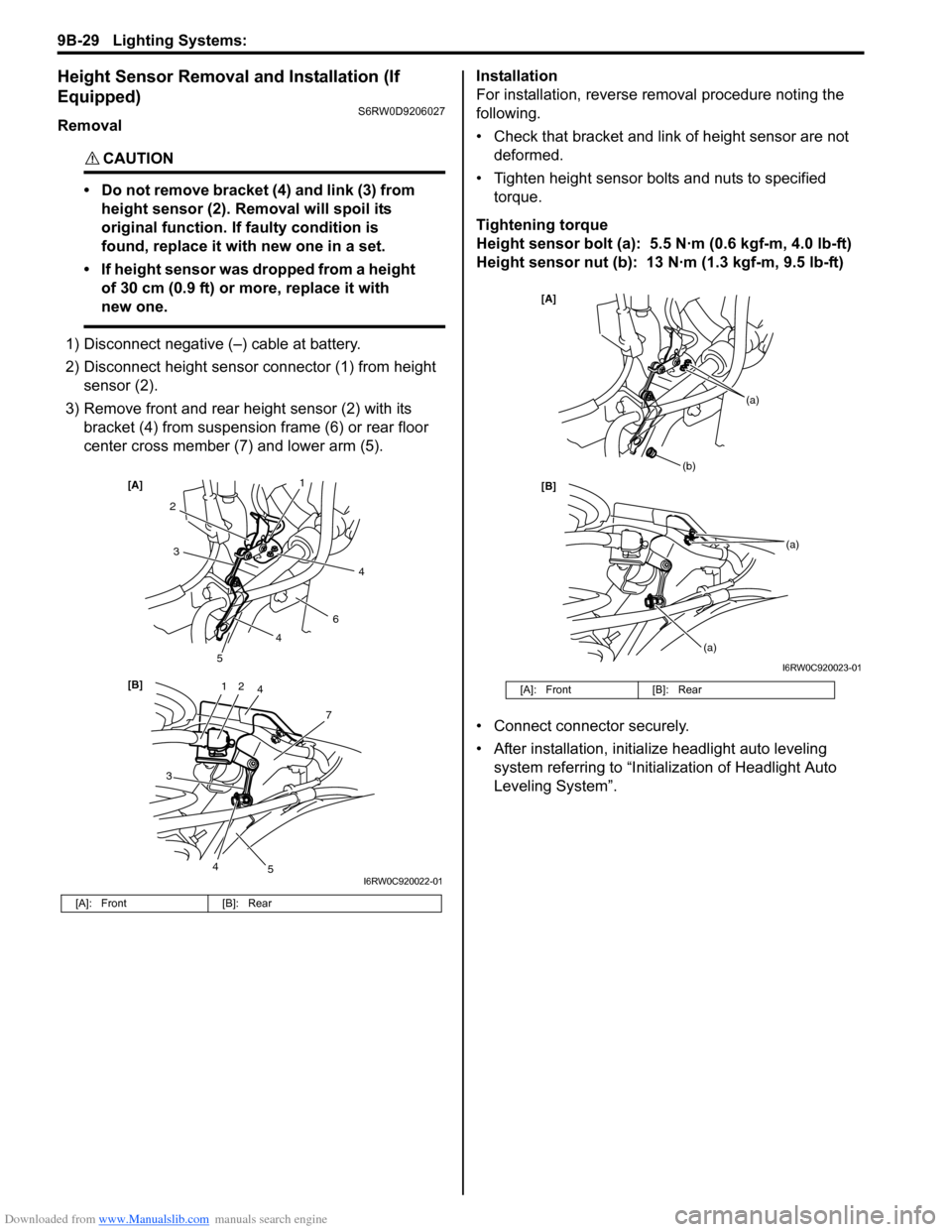
• Do not remove bracket (4) and link (3) from
height sensor (2). Removal will spoil its
original function. If faulty condition is
found, replace it with new one in a set.
• If height sensor was dropped from a height
of 30 cm (0.9 ft) or more, replace it with
new one.
1) Disconnect negative (–) cable at battery.
2) Disconnect height sensor connector (1) from height
sensor (2).
3) Remove front and rear height sensor (2) with its
bracket (4) from suspension frame (6) or rear floor
center cross member (7) and lower arm (5).Installation
For installation, reverse removal procedure noting the
following.
• Check that bracket and link of height sensor are not
deformed.
• Tighten height sensor bolts and nuts to specified
torque.
Tightening torque
Height sensor bolt (a): 5.5 N·m (0.6 kgf-m, 4.0 lb-ft)
Height sensor nut (b): 13 N·m (1.3 kgf-m, 9.5 lb-ft)
• Connect connector securely.
• After installation, initialize headlight auto leveling
system referring to “Initialization of Headlight Auto
Leveling System”.
[A]: Front [B]: Rear
12
7
[B] [A]
4
3
2
6
3
5
5
1
4
4
4
I6RW0C920022-01
[A]: Front [B]: Rear
[B] [A]
(b)
(a)
(a)
(a)
I6RW0C920023-01
Page 1349 of 1556
Downloaded from www.Manualslib.com manuals search engine Lighting Systems: 9B-30
Height Sensor and Its Circuit Inspection (If
Equipped)
S6RW0D9206028
1) Remove front or rear height sensor from vehicle
referring to “Height Sensor Removal and Installation
(If Equipped)”.
2) Connect connector to height sensor.
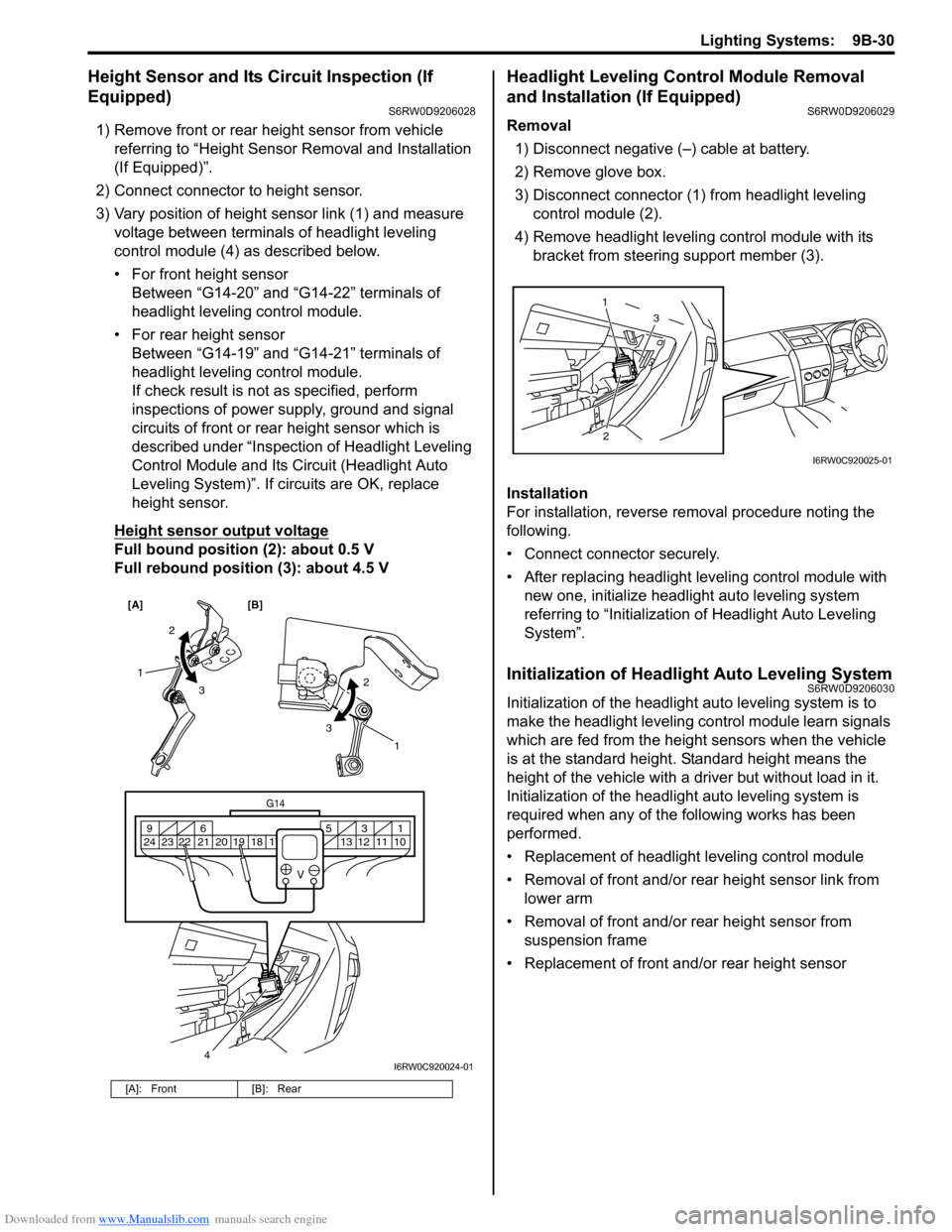
3) Vary position of height sensor link (1) and measure
voltage between terminals of headlight leveling
control module (4) as described below.
• For front height sensor
Between “G14-20” and “G14-22” terminals of
headlight leveling control module.
• For rear height sensor
Between “G14-19” and “G14-21” terminals of
headlight leveling control module.
If check result is not as specified, perform
inspections of power supply, ground and signal
circuits of front or rear height sensor which is
described under “Inspection of Headlight Leveling
Control Module and Its Circuit (Headlight Auto
Leveling System)”. If circuits are OK, replace
height sensor.
Height sensor output voltage
Full bound position (2): about 0.5 V
Full rebound position (3): about 4.5 V
Headlight Leveling Control Module Removal
and Installation (If Equipped)
S6RW0D9206029
Removal
1) Disconnect negative (–) cable at battery.
2) Remove glove box.
3) Disconnect connector (1) from headlight leveling
control module (2).
4) Remove headlight leveling control module with its
bracket from steering support member (3).
Installation
For installation, reverse removal procedure noting the
following.
• Connect connector securely.
• After replacing headlight leveling control module with
new one, initialize headlight auto leveling system
referring to “Initialization of Headlight Auto Leveling
System”.
Initialization of Headlight Auto Leveling SystemS6RW0D9206030
Initialization of the headlight auto leveling system is to
make the headlight leveling control module learn signals
which are fed from the height sensors when the vehicle
is at the standard height. Standard height means the
height of the vehicle with a driver but without load in it.
Initialization of the headlight auto leveling system is
required when any of the following works has been
performed.
• Replacement of headlight leveling control module
• Removal of front and/or rear height sensor link from
lower arm
• Removal of front and/or rear height sensor from
suspension frame
• Replacement of front and/or rear height sensor
[A]: Front [B]: Rear
[A] [B]
4
G14
10 11 12 13 16 17 18 19 2031 5 6 9
21 22 23 24
V
2
3 1
2
3
1
I6RW0C920024-01
23 1
I6RW0C920025-01
Page 1369 of 1556
Downloaded from www.Manualslib.com manuals search engine Instrumentation / Driver Info. / Horn: 9C-17
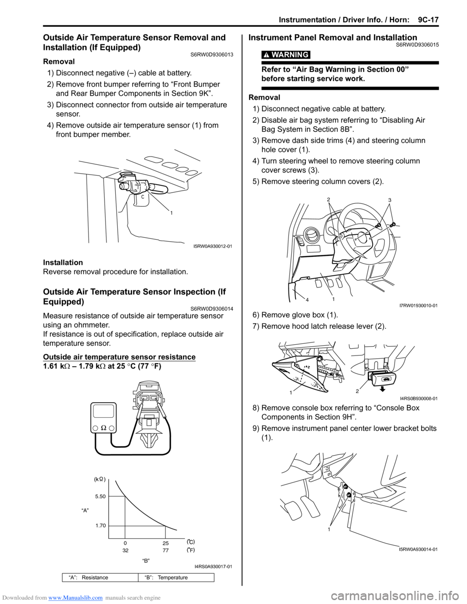
Outside Air Temperature Sensor Removal and
Installation (If Equipped)
S6RW0D9306013
Removal
1) Disconnect negative (–) cable at battery.
2) Remove front bumper referring to “Front Bumper
and Rear Bumper Components in Section 9K”.
3) Disconnect connector from outside air temperature
sensor.
4) Remove outside air temperature sensor (1) from
front bumper member.
Installation
Reverse removal procedure for installation.
Outside Air Temperature Sensor Inspection (If
Equipped)
S6RW0D9306014
Measure resistance of outside air temperature sensor
using an ohmmeter.
If resistance is out of specification, replace outside air
temperature sensor.
Outside air temperature sensor resistance
1.61 kΩ – 1.79 kΩ at 25 °C (77 °F)
Instrument Panel Removal and InstallationS6RW0D9306015
WARNING!
Refer to “Air Bag Warning in Section 00”
before starting service work.
Removal
1) Disconnect negative cable at battery.
2) Disable air bag system referring to “Disabling Air
Bag System in Section 8B”.
3) Remove dash side trims (4) and steering column
hole cover (1).
4) Turn steering wheel to remove steering column
cover screws (3).
5) Remove steering column covers (2).
6) Remove glove box (1).
7) Remove hood latch release lever (2).
8) Remove console box referring to “Console Box
Components in Section 9H”.
9) Remove instrument panel center lower bracket bolts
(1).
“A”: Resistance “B”: Temperature
1
I5RW0A930012-01
“B” “A”5.50
1.70
0
3225
77
F
I4RS0A930017-01
2
3
1
4I7RW01930010-01
2
1I4RS0B930008-01
1
I5RW0A930014-01
Page 1449 of 1556
Downloaded from www.Manualslib.com manuals search engine Body Structure: 9K-5
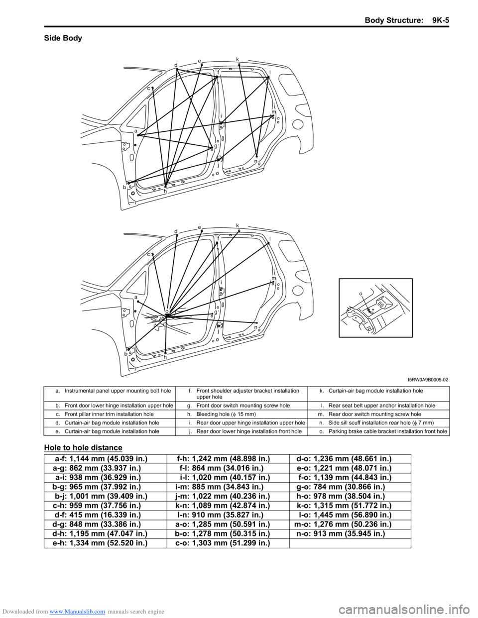
Side Body
Hole to hole distance
o
dek
fl
im
n
g
j
h
o
ac
b
dek
fl
im
n
g
j
h
ac
b
I5RW0A9B0005-02
a. Instrumental panel upper mounting bolt hole f. Front shoulder adjuster bracket installation
upper holek. Curtain-air bag module installation hole
b. Front door lower hinge installation upper hole g. Front door switch mounting screw hole l. Rear seat belt upper anchor installation hole
c. Front pillar inner trim installation hole h. Bleeding hole (φ 15 mm) m. Rear door switch mounting screw hole
d. Curtain-air bag module installation hole i. Rear door upper hinge installation upper hole n. Side sill scuff installation rear hole (φ 7 mm)
e. Curtain-air bag module installation hole j. Rear door lower hinge installation front hole o. Parking brake cable bracket installation front hole
a-f: 1,144 mm (45.039 in.) f-h: 1,242 mm (48.898 in.) d-o: 1,236 mm (48.661 in.)
a-g: 862 mm (33.937 in.) f-l: 864 mm (34.016 in.) e-o: 1,221 mm (48.071 in.)
a-i: 938 mm (36.929 in.) i-l: 1,020 mm (40.157 in.) f-o: 1,139 mm (44.843 in.)
b-g: 965 mm (37.992 in.) i-m: 885 mm (34.843 in.) g-o: 784 mm (30.866 in.)
b-j: 1,001 mm (39.409 in.) j-m: 1,022 mm (40.236 in.) h-o: 978 mm (38.504 in.)
c-h: 959 mm (37.756 in.) k-n: 1,089 mm (42.874 in.) k-o: 1,315 mm (51.772 in.)
d-f: 415 mm (16.339 in.) l-n: 910 mm (35.827 in.) l-o: 1,445 mm (56.890 in.)
d-g: 848 mm (33.386 in.) a-o: 1,285 mm (50.591 in.) m-o: 1,276 mm (50.236 in.)
d-h: 1,195 mm (47.047 in.) b-o: 1,278 mm (50.315 in.) n-o: 913 mm (35.945 in.)
e-h: 1,334 mm (52.520 in.) c-o: 1,303 mm (51.299 in.)