2006 SUZUKI SX4 Lights
[x] Cancel search: LightsPage 990 of 1556

Downloaded from www.Manualslib.com manuals search engine 7B-50 Air Conditioning System: Automatic Type
Not Using SUZUKI Scan Tool
NOTE
In case of malfunction of temperature
selector, blower speed selector and air flow
selector, DTC can not be checked by the
following procedure. Use SUZUKI scan tool
for DTC check.
1) Light over sunload sensor vertically with an
incandescent light of approximately 100 W apart
from about 100 mm (3.94 in.).
NOTE
If sunload sensor is not lighted over with an
incandescent light, DTC of sunload sensor is
detected as current DTC even though there is
not any malfunction.
2) Set the following selectors to specified positions
below respectively with ignition switch off position.
• Temperature selector (1) is maximum cool
position
• Blower speed selector (2) is OFF position
• Air flow selector (3) is AUTO position
3) While pressing A/C switch (4) and air intake selector
(5) simultaneously, turn ignition switch to ON
position.
4) Wait for about 5 seconds (start of diagnosis).
5) Read flashing pattern of “FRE” (6) and “REC” (7)
indicator lights which represents DTC and write it
down.
NOTE
• When 2 or more current DTCs are
detected, only DTC having the highest
priority is indicated. Therefore, after
troubleshooting the malfunction, DTC
check has to be performed again to see if
any other DTC(s) is detected.
• Pressing “A/C” switch alternates display
of current DTC and history DTC. “A/C”
indicator light (8) remains off when display
is in current DTC mode and it lights up
when display is in history DTC mode.
• When a history DTC is indicated while 2 or
more history DTCs are detected, it is
possible to have other history DTC(s)
stored in HVAC control module displayed
by pressing the air intake selector.
Example: When inside air temperature sensor
circuit malfunction (Open) is set
Example: When VSS signal failure (Data error) is
set
6) After completing above check, turn ignition switch to
“OFF” position.
[A]: “REC” indicator light L: OFF
[B]: “FRE” indicator light a. About 0.5 seconds
H: ON b. About 2 seconds
[A]: “REC” indicator light a. About 0.5 seconds
[B]: “FRE” indicator light b. About 3 seconds
H: ON c. About 1.5 seconds
L: OFF
123
458
6
7I5RW0A722005-01
[A]
[B]H
L
H
L [B]
[A]
ab
aI5RW0A722006-02
[A]
[B]H
L
H
L [B]
[A]
ab
aaaa
c
I5RW0A722025-01
Page 994 of 1556
![SUZUKI SX4 2006 1.G Service Workshop Manual Downloaded from www.Manualslib.com manuals search engine 7B-54 Air Conditioning System: Automatic Type
DTC of A/C System detected by ECM
NOTE
When no DTC is detected, “FRE” [A] and “REC” [B] i SUZUKI SX4 2006 1.G Service Workshop Manual Downloaded from www.Manualslib.com manuals search engine 7B-54 Air Conditioning System: Automatic Type
DTC of A/C System detected by ECM
NOTE
When no DTC is detected, “FRE” [A] and “REC” [B] i](/manual-img/20/7612/w960_7612-993.png)
Downloaded from www.Manualslib.com manuals search engine 7B-54 Air Conditioning System: Automatic Type
DTC of A/C System detected by ECM
NOTE
When no DTC is detected, “FRE” [A] and “REC” [B] indicator lights on HVAC control module flash at
the same time in specific pattern.
Fail-Safe TableS6RW0D7224007
When any of the following malfunctions (DTCs) is detected, fail-safe mode is activated.
However, when HVAC control module detects normal operation of A/C system, fail-safe mode is canceled. DTC No. Detection itemDetecting condition
(DTC will set when detecting)MIL
P0481 Fan 2 Control Circuit
Refer to “Fail-Safe Table in Section 1A”. P0532A/C Refrigerant Pressure
Sensor Circuit Low
P0533A/C Refrigerant Pressure
Sensor Circuit High
H: ON a. About 3 seconds
L: OFF b. About 1 seconds
DTC No. Trouble AreaFail-Safe Operation
When ignition switch is turned ON
after malfunction is already detectedWhen malfunction is detected during
ignition switch is ON
�) B1502Inside air temperature
sensor circuitHVAC control module maintains last
normal value.HVAC control module controls actuators
assuming that inside air temperature is
25 °C (77 °F).
�) B1503A/C evaporator
temperature sensor
circuitHVAC control module assuming that
evaporator temperature is 0 °C (32 °F).• HVAC control module turns off A/C
switch signal.
• HVAC control module controls
actuators assuming that evaporator
temperature is 0 °C (32 °F).
�) B1504 Sunload sensor circuitHVAC control module maintains last
normal value.HVAC control module controls actuators
assuming that amount of sunlight is 0 W/
m
2.
�) B1520Temperature selector
malfunctionHVAC control module maintains last
normal value.HVAC control module controls actuators
assuming that setting of temperature
selector is 25 °C (77 °F) position.
�) B1521Blower speed selector
malfunctionHVAC control module maintains last
normal value.HVAC control module controls actuators
assuming that setting of blower speed
selector is low (1st) position.
�) B1522Air flow selector
malfunctionHVAC control module maintains last
normal value.HVAC control module controls actuators
assuming that setting of air flow selector
is DEF position.
[A]
[A]H
L
H
L [B]
[B]
baaba
baaba
I5RW0A722008-01
Page 1025 of 1556
Downloaded from www.Manualslib.com manuals search engine Air Conditioning System: Automatic Type 7B-85
Blower Motor Controller InspectionS6RW0D7226012
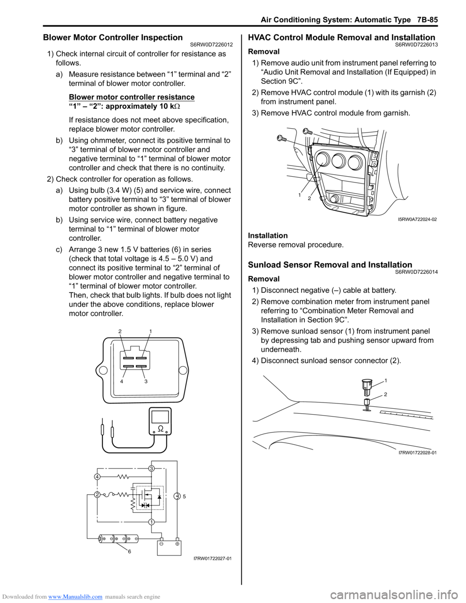
1) Check internal circuit of controller for resistance as
follows.
a) Measure resistance between “1” terminal and “2”
terminal of blower motor controller.
Blower motor controller resistance
“1” – “2”: approximately 10 kΩ
If resistance does not meet above specification,
replace blower motor controller.
b) Using ohmmeter, connect its positive terminal to
“3” terminal of blower motor controller and
negative terminal to “1” terminal of blower motor
controller and check that there is no continuity.
2) Check controller for operation as follows.
a) Using bulb (3.4 W) (5) and service wire, connect
battery positive terminal to “3” terminal of blower
motor controller as shown in figure.
b) Using service wire, connect battery negative
terminal to “1” terminal of blower motor
controller.
c) Arrange 3 new 1.5 V batteries (6) in series
(check that total voltage is 4.5 – 5.0 V) and
connect its positive terminal to “2” terminal of
blower motor controller and negative terminal to
“1” terminal of blower motor controller.
Then, check that bulb lights. If bulb does not light
under the above conditions, replace blower
motor controller.
HVAC Control Module Removal and InstallationS6RW0D7226013
Removal
1) Remove audio unit from instrument panel referring to
“Audio Unit Removal and Installation (If Equipped) in
Section 9C”.
2) Remove HVAC control module (1) with its garnish (2)
from instrument panel.
3) Remove HVAC control module from garnish.
Installation
Reverse removal procedure.
Sunload Sensor Removal and InstallationS6RW0D7226014
Removal
1) Disconnect negative (–) cable at battery.
2) Remove combination meter from instrument panel
referring to “Combination Meter Removal and
Installation in Section 9C”.
3) Remove sunload sensor (1) from instrument panel
by depressing tab and pushing sensor upward from
underneath.
4) Disconnect sunload sensor connector (2).
21
43
3
1 2 4
5
6I7RW01722027-01
12
I5RW0A722024-02
1
2
I7RW01722028-01
Page 1321 of 1556
Downloaded from www.Manualslib.com manuals search engine Lighting Systems: 9B-2
Igniter
Igniter generates high voltage needed to turn on the discharge headlight. It is charged with high voltage raised by the
ballast and it applies voltage pulse as high as about 20,000V to the tungsten electrode in the discharge headlight bulb.
After the discharge headlights light up, the ballast supplies voltage to bulbs.
Discharge headlight bulb
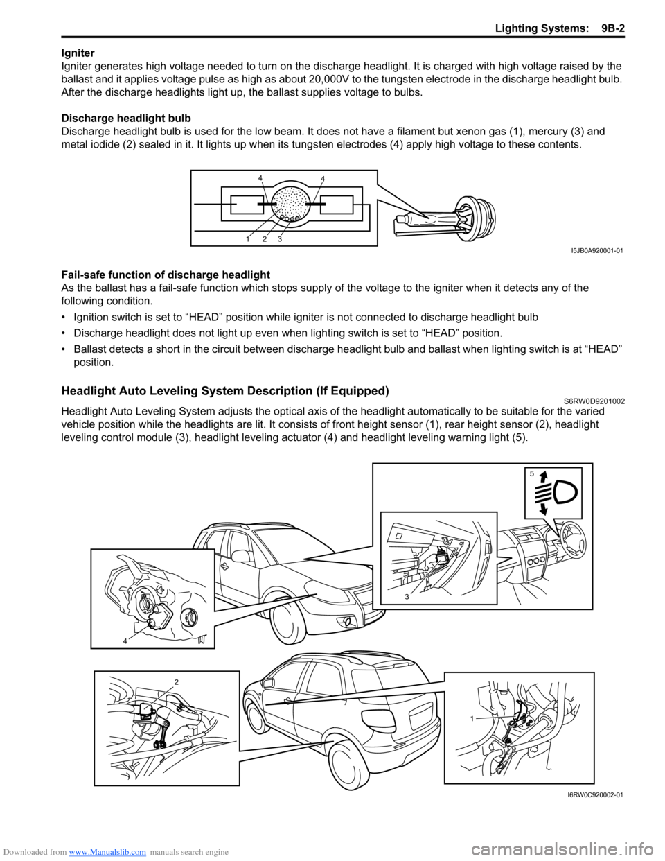
Discharge headlight bulb is used for the low beam. It does not have a filament but xenon gas (1), mercury (3) and
metal iodide (2) sealed in it. It lights up when its tungsten electrodes (4) apply high voltage to these contents.
Fail-safe function of discharge headlight
As the ballast has a fail-safe function which stops supply of the voltage to the igniter when it detects any of the
following condition.
• Ignition switch is set to “HEAD” position while igniter is not connected to discharge headlight bulb
• Discharge headlight does not light up even when lighting switch is set to “HEAD” position.
• Ballast detects a short in the circuit between discharge headlight bulb and ballast when lighting switch is at “HEAD”
position.
Headlight Auto Leveling System Description (If Equipped)S6RW0D9201002
Headlight Auto Leveling System adjusts the optical axis of the headlight automatically to be suitable for the varied
vehicle position while the headlights are lit. It consists of front height sensor (1), rear height sensor (2), headlight
leveling control module (3), headlight leveling actuator (4) and headlight leveling warning light (5).
123
44
I5JB0A920001-01
4
3
5
1
2
I6RW0C920002-01
Page 1323 of 1556
Downloaded from www.Manualslib.com manuals search engine Lighting Systems: 9B-4
Headlight leveling actuator
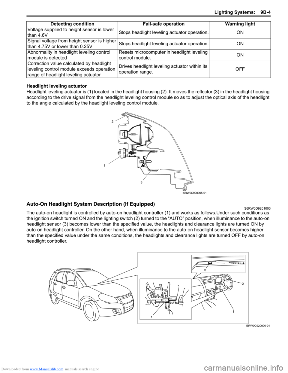
Headlight leveling actuator is (1) located in the headlight housing (2). It moves the reflector (3) in the headlight housing
according to the drive signal from the headlight leveling control module so as to adjust the optical axis of the headlight
to the angle calculated by the headlight leveling control module.
Auto-On Headlight System Description (If Equipped)S6RW0D9201003
The auto-on headlight is controlled by auto-on headlight controller (1) and works as follows.Under such conditions as
the ignition switch turned ON and the lighting switch (2) turned to the “AUTO” position, when illuminance to the auto-on
headlight sensor (3) becomes lower than the specified value, the headlights and clearance lights are turned ON by
auto-on headlight controller. On the other hand, when illuminance to the auto-on headlight sensor becomes higher
than the specified value under the same conditions, the headlights and clearance lights are turned OFF by auto-on
headlight controller.Voltage supplied to height sensor is lower
than 4.6VStops headlight leveling actuator operation. ON
Signal voltage from height sensor is higher
than 4.75V or lower than 0.25VStops headlight leveling actuator operation. ON
Abnormality in headlight leveling control
module is detectedResets microcomputer in headlight leveling
control module.ON
Correction value calculated by headlight
leveling control module exceeds operation
range of headlight leveling actuatorDrives headlight leveling actuator within its
operation range.OFF Detecting condition Fail-safe operation Warning light
1
3
2
I6RW0C920005-01
1 3
2
1
I6RW0C920006-01
Page 1327 of 1556
Downloaded from www.Manualslib.com manuals search engine Lighting Systems: 9B-8
Headlight Leveling Warning Light CheckS6RW0D9204015
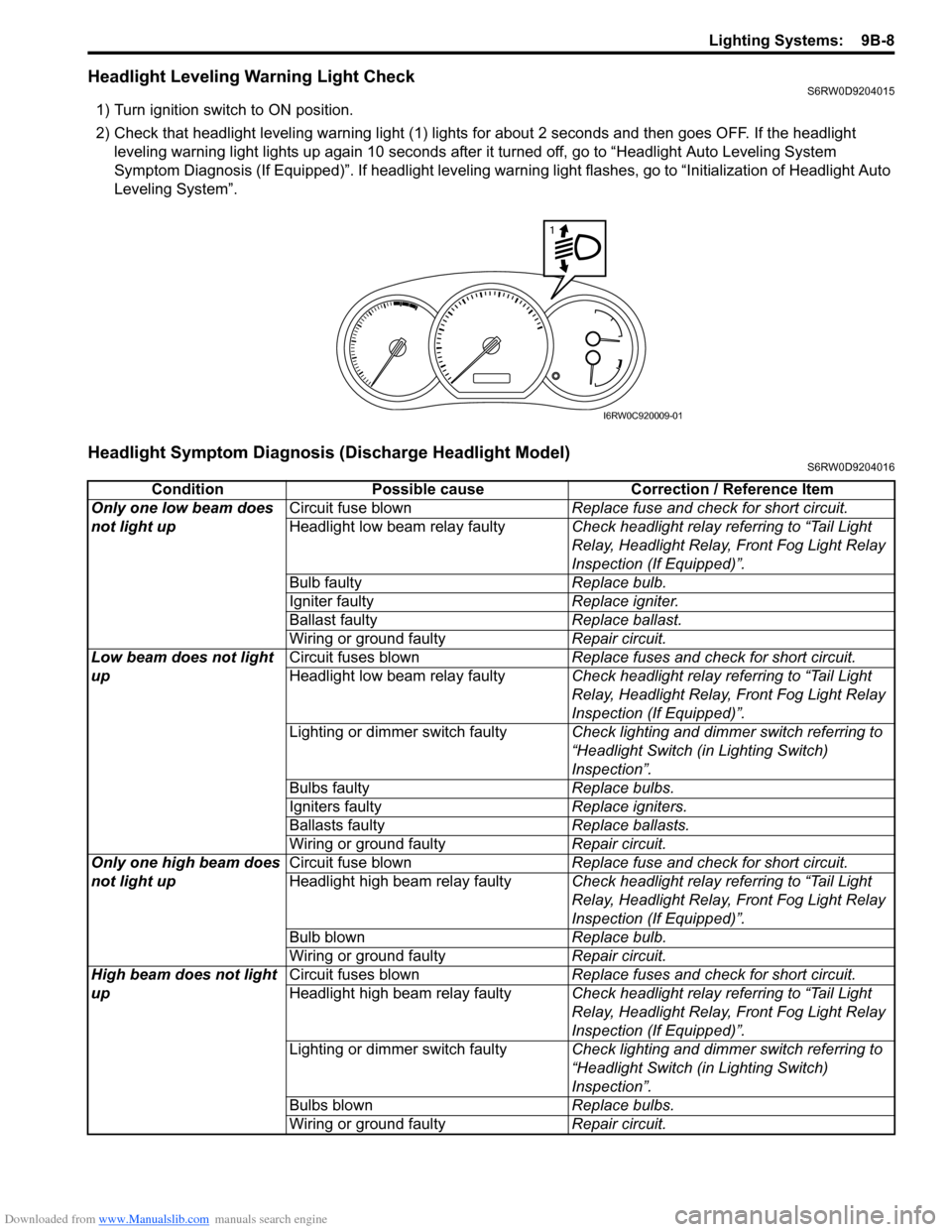
1) Turn ignition switch to ON position.
2) Check that headlight leveling warning light (1) lights for about 2 seconds and then goes OFF. If the headlight
leveling warning light lights up again 10 seconds after it turned off, go to “Headlight Auto Leveling System
Symptom Diagnosis (If Equipped)”. If headlight leveling warning light flashes, go to “Initialization of Headlight Auto
Leveling System”.
Headlight Symptom Diagnosis (Discharge Headlight Model)S6RW0D9204016
1
I6RW0C920009-01
Condition Possible cause Correction / Reference Item
Only one low beam does
not light upCircuit fuse blownReplace fuse and check for short circuit.
Headlight low beam relay faultyCheck headlight relay referring to “Tail Light
Relay, Headlight Relay, Front Fog Light Relay
Inspection (If Equipped)”.
Bulb faultyReplace bulb.
Igniter faultyReplace igniter.
Ballast faultyReplace ballast.
Wiring or ground faultyRepair circuit.
Low beam does not light
upCircuit fuses blownReplace fuses and check for short circuit.
Headlight low beam relay faultyCheck headlight relay referring to “Tail Light
Relay, Headlight Relay, Front Fog Light Relay
Inspection (If Equipped)”.
Lighting or dimmer switch faultyCheck lighting and dimmer switch referring to
“Headlight Switch (in Lighting Switch)
Inspection”.
Bulbs faultyReplace bulbs.
Igniters faultyReplace igniters.
Ballasts faultyReplace ballasts.
Wiring or ground faultyRepair circuit.
Only one high beam does
not light upCircuit fuse blownReplace fuse and check for short circuit.
Headlight high beam relay faultyCheck headlight relay referring to “Tail Light
Relay, Headlight Relay, Front Fog Light Relay
Inspection (If Equipped)”.
Bulb blownReplace bulb.
Wiring or ground faultyRepair circuit.
High beam does not light
upCircuit fuses blownReplace fuses and check for short circuit.
Headlight high beam relay faultyCheck headlight relay referring to “Tail Light
Relay, Headlight Relay, Front Fog Light Relay
Inspection (If Equipped)”.
Lighting or dimmer switch faultyCheck lighting and dimmer switch referring to
“Headlight Switch (in Lighting Switch)
Inspection”.
Bulbs blownReplace bulbs.
Wiring or ground faultyRepair circuit.
Page 1328 of 1556

Downloaded from www.Manualslib.com manuals search engine 9B-9 Lighting Systems:
Headlight Symptom diagnosis (Other than Discharge Headlight Model)S6RW0D9204017
Auto-On Headlight System Symptom Diagnosis (If Equipped)S6RW0D9204018
Condition Possible cause Correction / Reference Item
Only one low beam does
not light upCircuit fuse blownReplace fuse and check for short circuit.
Bulb blownReplace bulb.
Headlight low beam relay faulty (if
equipped)Check headlight relay referring to “Tail Light
Relay, Headlight Relay, Front Fog Light Relay
Inspection (If Equipped)”.
Wiring or ground faultyRepair circuit.
Low beam does not light
upCircuit fuse blownReplace fuses and check for short circuit.
Headlight low beam relay faulty (if
equipped)Check headlight relay referring to “Tail Light
Relay, Headlight Relay, Front Fog Light Relay
Inspection (If Equipped)”.
Lighting or dimmer switch faultyCheck lighting and dimmer switch referring to
“Headlight Switch (in Lighting Switch)
Inspection”.
Bulbs blownReplace bulbs.
Wiring or ground faultyRepair circuit.
DRL controller faulty (if equipped)Check system referring to “Inspection of DRL
Controller and Its Circuits (If Equipped)”.
Only one high beam does
not light upCircuit fuse blownReplace fuse and check for short circuit.
Bulb blownReplace bulb.
Headlight high beam relay faulty (if
equipped)Check headlight relay referring to “Tail Light
Relay, Headlight Relay, Front Fog Light Relay
Inspection (If Equipped)”.
Wiring or ground faultyRepair circuit.
High beam does not light
upCircuit fuse blownReplace fuses and check for short circuit.
Headlight high beam relay faulty (if
equipped)Check headlight relay referring to “Tail Light
Relay, Headlight Relay, Front Fog Light Relay
Inspection (If Equipped)”.
Lighting or dimmer switch faultyCheck lighting and dimmer switch referring to
“Headlight Switch (in Lighting Switch)
Inspection”.
Bulbs blownReplace bulbs.
Wiring or ground faultyRepair circuit.
Condition Possible cause Correction / Reference Item
Headlights are not turned
ON or OFF automatically
even after darkened or
lightenedCircuit fuse blownReplace fuse and check for short circuit.
Lighting or dimmer switch faultyCheck lighting and dimmer switch referring to
“Headlight Switch (in Lighting Switch)
Inspection”.
Auto-on headlight sensor faultyCheck auto-on headlight sensor referring to
“Auto-On Headlight Sensor Inspection (If
Equipped)”.
Wiring or ground faultyRepair circuit.
Auto-on headlight controller faultyCheck auto-on headlight controller for function
referring to “Inspection of Auto-On Headlight
Controller and Its Circuit (If Equipped)”.
Page 1329 of 1556
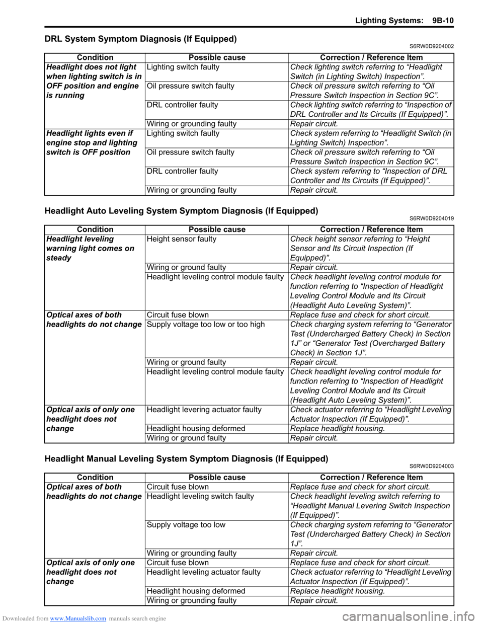
Downloaded from www.Manualslib.com manuals search engine Lighting Systems: 9B-10
DRL System Symptom Diagnosis (If Equipped)S6RW0D9204002
Headlight Auto Leveling System Symptom Diagnosis (If Equipped)S6RW0D9204019
Headlight Manual Leveling System Symptom Diagnosis (If Equipped)S6RW0D9204003
Condition Possible cause Correction / Reference Item
Headlight does not light
when lighting switch is in
OFF position and engine
is runningLighting switch faultyCheck lighting switch referring to “Headlight
Switch (in Lighting Switch) Inspection”.
Oil pressure switch faultyCheck oil pressure switch referring to “Oil
Pressure Switch Inspection in Section 9C”.
DRL controller faultyCheck lighting switch referring to “Inspection of
DRL Controller and Its Circuits (If Equipped)”.
Wiring or grounding faultyRepair circuit.
Headlight lights even if
engine stop and lighting
switch is OFF positionLighting switch faultyCheck system referring to “Headlight Switch (in
Lighting Switch) Inspection”.
Oil pressure switch faultyCheck oil pressure switch referring to “Oil
Pressure Switch Inspection in Section 9C”.
DRL controller faultyCheck system referring to “Inspection of DRL
Controller and Its Circuits (If Equipped)”.
Wiring or grounding faultyRepair circuit.
Condition Possible cause Correction / Reference Item
Headlight leveling
warning light comes on
steadyHeight sensor faultyCheck height sensor referring to “Height
Sensor and Its Circuit Inspection (If
Equipped)”.
Wiring or ground faultyRepair circuit.
Headlight leveling control module faultyCheck headlight leveling control module for
function referring to “Inspection of Headlight
Leveling Control Module and Its Circuit
(Headlight Auto Leveling System)”.
Optical axes of both
headlights do not changeCircuit fuse blownReplace fuse and check for short circuit.
Supply voltage too low or too highCheck charging system referring to “Generator
Test (Undercharged Battery Check) in Section
1J” or “Generator Test (Overcharged Battery
Check) in Section 1J”.
Wiring or ground faultyRepair circuit.
Headlight leveling control module faultyCheck headlight leveling control module for
function referring to “Inspection of Headlight
Leveling Control Module and Its Circuit
(Headlight Auto Leveling System)”.
Optical axis of only one
headlight does not
changeHeadlight levering actuator faultyCheck actuator referring to “Headlight Leveling
Actuator Inspection (If Equipped)”.
Headlight housing deformedReplace headlight housing.
Wiring or ground faultyRepair circuit.
Condition Possible cause Correction / Reference Item
Optical axes of both
headlights do not changeCircuit fuse blownReplace fuse and check for short circuit.
Headlight leveling switch faultyCheck headlight leveling switch referring to
“Headlight Manual Levering Switch Inspection
(If Equipped)”.
Supply voltage too lowCheck charging system referring to “Generator
Test (Undercharged Battery Check) in Section
1J”.
Wiring or grounding faultyRepair circuit.
Optical axis of only one
headlight does not
changeCircuit fuse blownReplace fuse and check for short circuit.
Headlight leveling actuator faultyCheck actuator referring to “Headlight Leveling
Actuator Inspection (If Equipped)”.
Headlight housing deformedReplace headlight housing.
Wiring or grounding faultyRepair circuit.