2006 SUZUKI SX4 Board
[x] Cancel search: BoardPage 965 of 1556

Downloaded from www.Manualslib.com manuals search engine Air Conditioning System: Manual Type 7B-25
HVAC Unit ComponentsS6RW0D7216007
NOTE
The figure shows left-hand steering vehicle. For right-hand steering vehicle, parts with (*) are installed
at the opposite side.
1
10
1
9
8
25
25
3
20
3
19 19
19
24
24 21
4
23*27 15 16* 14
25*18*2
2526
17*1312 11
5*22
67
*
26
5*
I6RW0C721006-01
1. Blower upper case 8. Air intake control actuator 15. Evaporator 22. Temperature control door
assembly
2. Blower lower case 9. Air intake control link 16. Evaporator temperature sensor 23. Drain hose
3. Heater unit upper case 10. Air intake control door 17. Expansion valve 24. Cable lock clamp
4. Heater unit lower case 11. Blower motor 18. Expansion pipe 25. Packing
5. Foot duct 12. Blower motor cap 19. Air flow control lever 26. O-ring
: Apply compressor oil.
6. HVAC air filter (if equipped) 13. Blower motor resister 20. Air flow control door assembly 27. Resistance board (non-A/C)
Page 981 of 1556

Downloaded from www.Manualslib.com manuals search engine Air Conditioning System: Automatic Type 7B-41
On-Board Diagnostic System DescriptionS6RW0D7221004
NOTE
The diagnostic information as diagnostic
trouble code (DTC) can be known by using
SUZUKI scan tool. For further details, refer to
“DTC Check”.
HVAC control module detects malfunctions, which may
occur in the following area.
• Inside air temperature sensor
• Evaporator temperature sensor
• Sunload sensor
• Temperature control actuator
• Air flow control actuator
• Temperature selector of HVAC control module
• Air flow selector of HVAC control module
• Blower speed selector of HVAC control module
• Back-up power supply circuit of HAVC control module
• Serial communication line between BCM and HVAC
control module• Received data from BCM as follows
– Outside air temperature sensor signal
– ECT sensor signal
– A/C refrigerant pressure sensor signal
– VSS signal
– Engine type signal
– Combination meter spec signal
– CAN communication circuit failure signal
When HVAC control module detects malfunction, the “A/
C” indicator light (1) flashes to warn and the diagnostic
trouble code (DTC) is stored in the memory of the
module. When diagnosing trouble, the DTC can be
checked according to “DTC Check”.
Schematic and Routing Diagram
A/C System Air Flow DiagramS6RW0D7222001
Refer to “A/C System Air Flow Diagram”.
1
I5RW0A722002-01
Page 1040 of 1556
Downloaded from www.Manualslib.com manuals search engine 8B-1 Air Bag System:
Restraint
Air Bag System
Precautions
Precautions on Service and Diagnosis of Air
Bag System
S6RW0D8200004
WARNING!
• If the air bag system and another vehicle
system both need repair, SUZUKI
recommends that the air bag system be
repaired first, to help avoid unintended air
bag system activation.
• Do not modify the steering wheel,
dashboard, both front seat or any other on
or around air bag system components.
Modifications can adversely affect air bag
system performance and lead to injury.
• Be sure to follow the procedures described
in this section. Failure to follow
procedures could result in possible air bag
system activation, personal injury or
unneeded air bag system repairs.
• WARNING / CAUTION labels are attached on each
part of air bag system components (SDM, air bag
(inflator) modules and seat belt pretensioners). Be
sure to follow the instructions.
• Many of service procedures require disconnection of
“A/B” fuse and air bag (inflator) module(s) (driver
module, passenger module, side modules and curtain
modules) from initiator circuit to avoid an accidental
deployment.
• Do not apply power to the air bag system unless all
components are connected or a diagnostic flow
requests it, as this will set a DTC.
• The “Air Bag Diagnostic System Check” must be the
starting point of any air bag diagnostics. The “Air Bag
Diagnostic System Check” will verify proper “AIR
BAG” warning light operation and will lead you to the
correct flow to diagnose any air bag malfunctions.
Bypassing these procedures may result in extended
diagnostic time, incorrect diagnosis, and incorrect
parts replacements.
• Never use air bag component parts from another
vehicle.
• If the vehicle will be exposed to temperatures over 93
°C (200 °F) (for example, during a paint baking
process), remove the air bag system components
beforehand to avoid component damage or
unintended system activation.• When handling the air bag (inflator) modules (driver
module, passenger module, side modules and curtain
modules), seat belt pretensioners (driver module and
passenger module), SDM, forward impact-sensor or
side impact-sensor be careful not to drop it or apply
an impact to it. If an excessive impact was applied
(e.g., SDM, forward impact-sensor are dropped, air
bag (inflator) module is dropped from a height of 90
cm (3 ft) or more, seat belt pretensioner (retractor
assembly) is dropped from a height of 30 cm (1 ft) or
more), never attempt disassembly or repair but
replace it with a new one.
• When using electric welding, be sure to disconnect air
bag (inflator) module connectors (driver module,
passenger module, side modules and curtain
modules) and seat belt pretensioner connectors
(driver module and passenger module) respectively.
• When applying paint around the air bag system
related parts, use care so that the harness or
connector will not be exposed to the paint mist.
• Never expose air bag system component parts
directly to hot air (drying or baking the vehicle after
painting) or flames.
WARNING!
When performing service on or around air
bag system components or air bag wiring,
follow the procedures listed in “Disabling Air
Bag System” to temporarily disable the air
bag system.
Failure to follow procedures could result in
possible air bag system activation, personal
injury or unneeded air bag system repairs.
Precautions on Handling and Storage of Air Bag
System Components
S6RW0D8200002
SDM
WARNING!
Never power up air bag system when SDM is
not rigidly attached to the vehicle. Otherwise,
personal injury may result.
CAUTION!
After detecting one time of such collision as
to meet deployment conditions, SDM must
not be used. Refer to “Air Bag Diagnostic
System Check” when checking SDM.
Page 1339 of 1556
Downloaded from www.Manualslib.com manuals search engine Lighting Systems: 9B-20
Igniter Removal and Installation (Discharge
Headlight Model)
S6RW0D9206024
WARNING!
Be sure to read “Precautions for Discharge
Headlight Service (If Equipped)” carefully
before working. Neglecting them may result
in personal injury.
Removal
1) Remove ballast referring to “Ballast Removal and
Installation (Discharge Headlight Model)”.
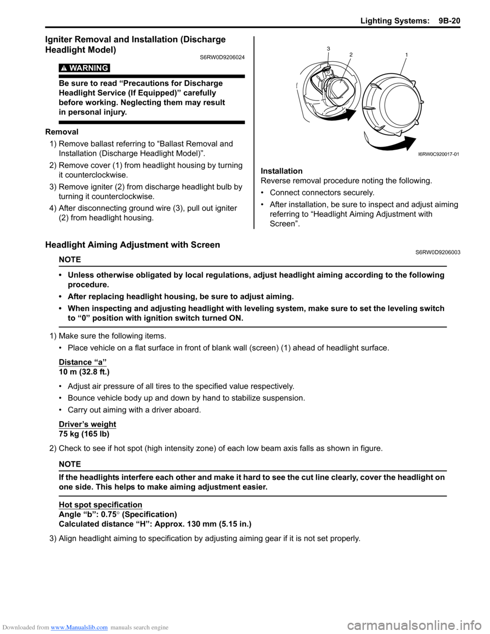
2) Remove cover (1) from headlight housing by turning
it counterclockwise.
3) Remove igniter (2) from discharge headlight bulb by
turning it counterclockwise.
4) After disconnecting ground wire (3), pull out igniter
(2) from headlight housing.Installation
Reverse removal procedure noting the following.
• Connect connectors securely.
• After installation, be sure to inspect and adjust aiming
referring to “Headlight Aiming Adjustment with
Screen”.
Headlight Aiming Adjustment with ScreenS6RW0D9206003
NOTE
• Unless otherwise obligated by local regulations, adjust headlight aiming according to the following
procedure.
• After replacing headlight housing, be sure to adjust aiming.
• When inspecting and adjusting headlight with leveling system, make sure to set the leveling switch
to “0” position with ignition switch turned ON.
1) Make sure the following items.
• Place vehicle on a flat surface in front of blank wall (screen) (1) ahead of headlight surface.
Distance “a”
10 m (32.8 ft.)
• Adjust air pressure of all tires to the specified value respectively.
• Bounce vehicle body up and down by hand to stabilize suspension.
• Carry out aiming with a driver aboard.
Driver’s weight
75 kg (165 lb)
2) Check to see if hot spot (high intensity zone) of each low beam axis falls as shown in figure.
NOTE
If the headlights interfere each other and make it hard to see the cut line clearly, cover the headlight on
one side. This helps to make aiming adjustment easier.
Hot spot specification
Angle “b”: 0.75° (Specification)
Calculated distance “H”: Approx. 130 mm (5.15 in.)
3) Align headlight aiming to specification by adjusting aiming gear if it is not set properly.
2
1 3
I6RW0C920017-01
Page 1345 of 1556
Downloaded from www.Manualslib.com manuals search engine Lighting Systems: 9B-26
Front Fog Light Assembly Removal and
Installation (If Equipped)
S6RW0D9206014
WARNING!
• To avoid danger of being burned, don’t
touch when the bulb is hot.
• Don’t touch glass surface of bulb to avoid
deteriorate as the case may be unclear
when bulb light on at dirty condition.
Removal
1) Disconnect negative (–) cable at battery.
2) Remove front bumper. Refer to “Front Bumper and
Rear Bumper Components in Section 9K”.
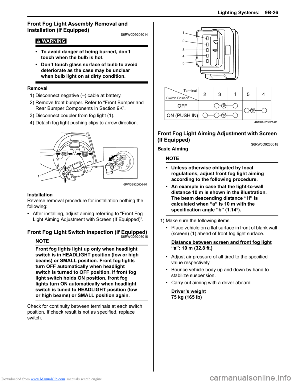
3) Disconnect coupler from fog light (1).
4) Detach fog light pushing clips to arrow direction.
Installation
Reverse removal procedure for installation nothing the
following:
• After installing, adjust aiming referring to “Front Fog
Light Aiming Adjustment with Screen (If Equipped)”.
Front Fog Light Switch Inspection (If Equipped)S6RW0D9206016
NOTE
Front fog lights light up only when headlight
switch is in HEADLIGHT position (low or high
beams) or SMALL position. Front fog lights
turn OFF automatically when headlight
switch is turned to OFF position. If front fog
light switch holds ON position, front fog
lights turn ON automatically when headlight
switch is tuned to HEADLIGHT position (low
or high beams) or SMALL position again.
Check for continuity between terminals at each switch
position. If check result is not as specified, replace
switch.
Front Fog Light Aiming Adjustment with Screen
(If Equipped)
S6RW0D9206018
Basic Aiming
NOTE
• Unless otherwise obligated by local
regulations, adjust front fog light aiming
according to the following procedure.
• An example in case that the light-to-wall
distance 10 m is shown in the illustration.
The beam descending distance “H” is
calculated when “a” is 10 m with the
specification angle “b” (1.14°).
1) Make sure the following items.
• Place vehicle on a flat surface in front of blank wall
(screen) (1) ahead of front fog light surface.
Distance between screen and front fog light
“a”: 10 m (32.8 ft.)
• Adjust air pressure of all tired to the specified
value respectively.
• Bounce vehicle body up and down by hand to
stabilize suspension.
• Carry out aiming with a driver aboard.
Driver’s weight
75 kg (165 lb)
1
I6RW0B920006-01
1
2
3
4
5
Switch PositionTerminal
ON (PUSH IN)231
54
OFF
I4RS0A920021-01
Page 1350 of 1556
Downloaded from www.Manualslib.com manuals search engine 9B-31 Lighting Systems:
Without initialization of the headlight auto leveling
system, it is not possible to obtain its proper function.
Also, if the headlight auto leveling system is not
initialized after replacing the headlight leveling control
module, the headlight leveling warning light in the
combination meter flashes.
1) Observe the following instructions.
• Park vehicle on level ground.
• Adjust air pressure of all tires to the specified
value respectively.
• Bounce vehicle body up and down by hand to
stabilize suspension.
2) Turn ignition switch to ON position.
3) Perform “Headlight Leveling Warning Light Check”.
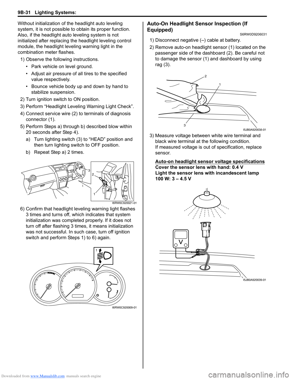
4) Connect service wire (2) to terminals of diagnosis
connector (1).
5) Perform Steps a) through b) described blow within
20 seconds after Step 4).
a) Turn lighting switch (3) to “HEAD” position and
then turn lighting switch to OFF position.
b) Repeat Step a) 2 times.
6) Confirm that headlight leveling warning light flashes
3 times and turns off, which indicates that system
initialization was completed properly. If it does not
turn off after flashing 3 times, it means initialization
was not successful. In such case, turn off ignition
switch and perform Steps 1) to 6) again.Auto-On Headlight Sensor Inspection (If
Equipped)
S6RW0D9206031
1) Disconnect negative (–) cable at battery.
2) Remove auto-on headlight sensor (1) located on the
passenger side of the dashboard (2). Be careful not
to damage the sensor (1) and dashboard by using
rag (3).
3) Measure voltage between white wire terminal and
black wire terminal at the following condition.
If measured voltage is out of specification, replace
sensor.
Auto-on headlight sensor voltage specifications
Cover the sensor lens with hand: 0.4 V
Light the sensor lens with incandescent lamp
100 W: 3 – 4.5 V3
1
2
I6RW0C920021-01
1
I6RW0C920009-01
2
1
3I5JB0A920038-01
I5JB0A920039-01
Page 1424 of 1556
Downloaded from www.Manualslib.com manuals search engine 9F-13 Security and Locks:
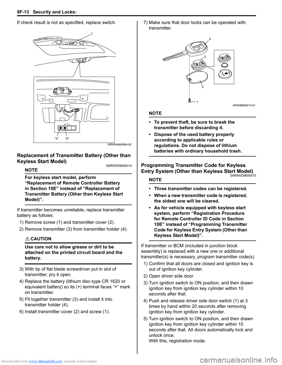
If check result is not as specified, replace switch.
Replacement of Transmitter Battery (Other than
Keyless Start Model)
S6RW0D9606014
NOTE
For keyless start model, perform
“Replacement of Remote Controller Battery
in Section 10E” instead of “Replacement of
Transmitter Battery (Other than Keyless Start
Model)”.
If transmitter becomes unreliable, replace transmitter
battery as follows.
1) Remove screw (1) and transmitter cover (2).
2) Remove transmitter (3) from transmitter holder (4).
CAUTION!
Use care not to allow grease or dirt to be
attached on the printed circuit board and the
battery.
3) With tip of flat blade screwdriver put in slot of
transmitter, pry it open.
4) Replace the battery (lithium disc-type CR 1620 or
equivalent battery) so its (+) terminal faces “+” mark
on transmitter.
5) Fit together transmitter (3) and install it into
transmitter holder (4).
6) Install transmitter cover (2) and screw (1).7) Make sure that door locks can be operated with
transmitter.
NOTE
• To prevent theft, be sure to break the
transmitter before discarding it.
• Dispose of the used battery properly
according to applicable rules or
regulations. Do not dispose of lithium
batteries with ordinary household trash.
Programming Transmitter Code for Keyless
Entry System (Other than Keyless Start Model)
S6RW0D9606015
NOTE
• Three transmitter codes can be registered.
• When a new transmitter code is registered,
the oldest one will be cleared.
• As for vehicle equipped with keyless start
system, perform “Registration Procedure
for Remote Controller ID Code in Section
10E” instead of “Programming Transmitter
Code for Keyless Entry System (Other than
Keyless Start Model)”.
If transmitter or BCM (included in junction block
assembly) is replaced with a new one or additional
transmitter(s) is necessary, program transmitter code(s).
1) Confirm that all doors are closed and ignition key is
out of ignition key cylinder.
2) Open driver side door.
3) Turn ignition switch to ON position, and then drawn
ignition key from ignition key cylinder within 10
seconds after that.
4) Push and release driver side door switch (1) at 3
times by hand within 20 seconds after removing
ignition key from ignition key cylinder.
5) Turn ignition switch to ON position, and then drawn
ignition key from ignition key cylinder within 10
seconds after that. All doors automatically lock and
unlock once.
With this, registration mode.
1
“a”
“b”
I5RW0A960009-02
234
1I4RS0B960014-01
Page 1471 of 1556
Downloaded from www.Manualslib.com manuals search engine Table of Contents 10- i
10
Section 10
CONTENTS
Control Systems
Precautions ............................................... 10-1
Precautions........................................................... 10-1
Precautions for Control Systems......................... 10-1
Body Electrical Control System ........... 10B-1
Precautions......................................................... 10B-1
Precautions in Diagnosing Trouble ................... 10B-1
General Description ........................................... 10B-1
BCM General Description ................................. 10B-1
CAN Communication System Description......... 10B-1
Theft Deterrent Light ......................................... 10B-2
Security Alarm Description (If Equipped) .......... 10B-2
Schematic and Routing Diagram ...................... 10B-3
Body Electrical Control System Wiring Circuit
Diagram .......................................................... 10B-3
Connector Layout Diagram of BCM and
Junction Block ................................................. 10B-6
Component Location ......................................... 10B-7
BCM and Related System Component
Location .......................................................... 10B-7
Diagnostic Information and Procedures .......... 10B-8
BCM Self-Diagnosis Function ........................... 10B-8
Body Electrical Control System Check.............. 10B-9
Scan Tool Data ............................................... 10B-11
DTC Table ....................................................... 10B-13
DTC Check ..................................................... 10B-14
DTC Clearance ............................................... 10B-15
BCM Power Circuit and Ground Circuit Check 10B-16
DTC B1133 (DTC No. 1133): Battery Voltage
Too High ....................................................... 10B-17
DTC B1141 / DTC B1142 (No. 1141 / No.
1142) Outside Air Temperature (Ambient
Temp.) Sensor Circuit Malfunction ................ 10B-18
DTC B1150 (No. 1150): Air Bag
Communication Circuit Malfunction .............. 10B-19
DTC B1157 (No. 1157) Air Bag Deployment
Signal Input ................................................... 10B-20
DTC B1170 (No. 1170): EEPROM Access
Error .............................................................. 10B-20
DTC U0073 (No. 0073): Control Module
Communication Bus Off ................................ 10B-20
DTC U0100 (No. 0100): Lost Communication
with ECM....................................................... 10B-20DTC U0101 (No. 0101): Lost Communication
with TCM ....................................................... 10B-20
DTC U0155 (No. 0155): Lost Communication
with Instrument Panel Cluster (IPC) Control
Module .......................................................... 10B-20
DTC U1144 (No. 1144): Lost Communication
with Keyless Start Control Module ................ 10B-20
Inspection of BCM and Its Circuits .................. 10B-21
Repair Instructions ..........................................10B-28
BCM (Included in Junction Block) Removal
and Installation .............................................. 10B-28
Security Alarm Mode Selection Procedure (If
Equipped) ...................................................... 10B-29
Outside Air Temperature Sensor Removal
and Installation .............................................. 10B-29
Outside Air Temperature Sensor Inspection ... 10B-29
Special Tools and Equipment .........................10B-29
Special Tool .................................................... 10B-29
Immobilizer Control System ................. 10C-1
Precautions.........................................................10C-1
Precautions in Diagnosing Troubles .................10C-1
Precaution in Replacing ECM ...........................10C-1
Precaution in Replacing Ignition Key ................10C-1
Precautions in Handling Immobilizer Control
System ............................................................10C-1
General Description ...........................................10C-2
Immobilizer Control System Introduction ..........10C-2
On-Board Diagnostic System Description
(Self-diagnosis Function)................................10C-2
Schematic and Routing Diagram ......................10C-3
Immobilizer Control System Wiring Circuit
Diagram...........................................................10C-3
Component Location .........................................10C-5
Immobilizer Control System Components
Location...........................................................10C-5
Diagnostic Information and Procedures ..........10C-5
Immobilizer Control System Check ...................10C-5
DTC Check........................................................10C-6
DTC Clearance .................................................10C-6
DTC Table .........................................................10C-7
Scan Tool Data .................................................10C-8
Immobilizer Indicator Light Does Not Come
ON with Ignition Switch ON and Engine Stop ..10C-9