2006 SUZUKI SX4 4WD
[x] Cancel search: 4WDPage 300 of 1556

Downloaded from www.Manualslib.com manuals search engine 1D-18 Engine Mechanical:
17) Remove oil pressure switch bracket (1).
18) Remove suspension control arm referring to
“Suspension Control Arm / Bushing Removal and
Installation in Section 2B”.
19) Disconnect right and left drive shaft joints from
differential gear referring to “Front Drive Shaft
Assembly Removal and Installation in Section 3A”.
20) Remove exhaust No.1, No.2 and center pipes
referring to “Exhaust System Components in Section
1K”.
21) Disconnect propeller shaft referring to “Propeller
Shaft Assembly Removal and Installation in Section
3D” (for 4WD model).
22) Disconnect steering lower shaft from pinion shaft
referring to “Steering Lower Shaft Removal and
Installation in Section 6B”.
23) Fix radiator to body with rope in order to avoid the
radiator fall off when front lower cross member
lowered.
24) Support front suspension frame, front lower cross
member and oil pan using jack at hatched parts (1)
indicated in figure.
[A]: View A [C]: For A/T model
6
3 45
1 7 7
2
8
9
10
A
15
14
16
20 19
26
24
27
12
13 [A]
11
34
232122
25
17 2818 [B] [C]
2930
31
32
17
33
I5RW0C140010-01
[B]: For M/T model 34. steering gear box
2. Exhaust manifold
1
2
I5RW0A140011-01
11
I5RW0A140012-01
Page 301 of 1556

Downloaded from www.Manualslib.com manuals search engine Engine Mechanical: 1D-19
25) Remove engine right mounting bracket (1) and
engine left mounting bush bolt (2).
26) Remove suspension frame mounting bolts and (1)
front lower cross member bolts (2).27) Lower engine with transaxle, front suspension frame,
front lower cross member, transfer (for 4WD model)
and steering gear case.
CAUTION!
Before lowering engine, in order to avoid
damage to A/C compressor, make clearance
by rising it.
28) Disconnect steering gear case from suspension
frame referring to “Steering Gear Case Assembly
Components in Section 6C”, if necessary.
29) Disconnect transfer from suspension frame referring
to “Transfer Dismounting and Remounting in Section
3C”, if necessary.
30) Disconnect transaxle from engine referring to
“Manual Transaxle Unit Dismounting and
Remounting in Section 5B” or “Automatic Transaxle
Unit Dismounting and Remounting in Section 5A”, if
necessary.
31) Remove clutch cover and clutch disk referring to
“Clutch Cover, Clutch Disc and Flywheel Removal
and Installation in Section 5C”, if necessary.
Installation
1) Install clutch cover and clutch disk referring to
“Clutch Cover, Clutch Disc and Flywheel Removal
and Installation in Section 5C”, if removed.
2) Connect transaxle to engine referring to “Manual
Transaxle Unit Dismounting and Remounting in
Section 5B” or “Automatic Transaxle Unit
Dismounting and Remounting in Section 5A”, if
removed.
3) Connect transfer to suspension frame referring to
“Transfer Dismounting and Remounting in Section
3C”, if removed.
4) Connect steering gear case to suspension frame
referring to “Steering Gear Case Assembly
Components in Section 6C”, if removed.
5) Lift engine with transaxle, front suspension frame,
front lower cross member, transfer and steering gear
case into engine compartment with jack.
CAUTION!
Before lifting engine, in order to avoid
damage to A/C compressor, make clearance
by rising it.
1
2
I5RW0C140012-01
2
1
I5RW0A140014-01
Page 302 of 1556

Downloaded from www.Manualslib.com manuals search engine 1D-20 Engine Mechanical:
6) Install engine right mounting bracket (1) and engine
left mounting bush bolt (2), and then tighten bolt and
nuts to specified torque.
Tightening torque
Engine right mounting bracket nut (a): 65 N·m (
6.5 kgf-m, 47.0 lb-ft)
Engine right mounting bush bolt (b): 55 N·m (5.5
kgf-m, 40.0 lb-ft)
Engine left mounting bush bolt (c): 85 N·m (8.5
kgf-m, 61.5 lb-ft)
7) Install suspension frame mounting bolts (1) and front
lower cross member bolts (2). And then tighten bolts
to specified torque.
Tightening torque
Suspension frame mounting bolt (a): 150 N·m (
15.0 kgf-m, 108.5 lb-ft)
Front lower cross member bolt (b): 55 N·m (5.5
kgf-m, 40.0 lb-ft)8) Connect steering lower shaft from pinion shaft
referring to “Steering Lower Shaft Removal and
Installation in Section 6B”.
9) Connect propeller shaft referring to “Propeller Shaft
Assembly Removal and Installation in Section 3D”
(for 4WD model)
10) Install exhaust No.1, No.2 and center pipes referring
to “Exhaust System Components in Section 1K”.
11) Reverse disconnected hoses, cables and electric
wires for connection noting the following.
• Tighten bolts and nuts to specified torque.
Tightening torque
Starting motor terminal nut (a): 11 N·m (1.1 kgf-
m, 8.0 lb-ft)
Generator terminal nut (b): 5 N·m (0.5 kgf-m, 4.0
lb-ft)
Battery ground bolt (c): 25 N·m (2.5 kgf-m, 18.0
lb-ft)
Ground terminal bolt (d): 11 N·m (1.1 kgf-m, 8.0
lb-ft)
1
(b)(a)
2,(c)
I5RW0C140031-01
2,(b)
1,(a)
I5RW0A140016-01
[A]: For M/T model [B]: For A/T model
(d)
(a)
(b)
(c)
(c)
[A]
[B]
I5RW0C140013-02
Page 360 of 1556

Downloaded from www.Manualslib.com manuals search engine 1E-4 Engine Lubrication System:
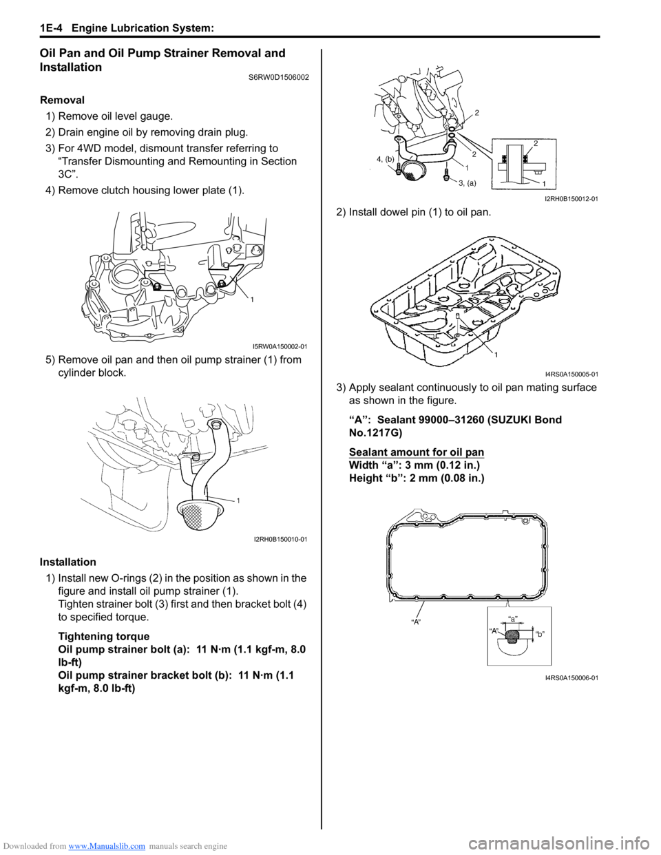
Oil Pan and Oil Pump Strainer Removal and
Installation
S6RW0D1506002
Removal
1) Remove oil level gauge.
2) Drain engine oil by removing drain plug.
3) For 4WD model, dismount transfer referring to
“Transfer Dismounting and Remounting in Section
3C”.
4) Remove clutch housing lower plate (1).
5) Remove oil pan and then oil pump strainer (1) from
cylinder block.
Installation
1) Install new O-rings (2) in the position as shown in the
figure and install oil pump strainer (1).
Tighten strainer bolt (3) first and then bracket bolt (4)
to specified torque.
Tightening torque
Oil pump strainer bolt (a): 11 N·m (1.1 kgf-m, 8.0
lb-ft)
Oil pump strainer bracket bolt (b): 11 N·m (1.1
kgf-m, 8.0 lb-ft)2) Install dowel pin (1) to oil pan.
3) Apply sealant continuously to oil pan mating surface
as shown in the figure.
“A”: Sealant 99000–31260 (SUZUKI Bond
No.1217G)
Sealant amount for oil pan
Width “a”: 3 mm (0.12 in.)
Height “b”: 2 mm (0.08 in.)
1
I5RW0A150002-01
I2RH0B150010-01
I2RH0B150012-01
I4RS0A150005-01
I4RS0A150006-01
Page 361 of 1556

Downloaded from www.Manualslib.com manuals search engine Engine Lubrication System: 1E-5
4) Install oil pan to cylinder block temporarily.
5) Insert dowel pin (1) in hole (2) of oil pan in order to
locate oil pan precisely.
NOTE
Dowel pin is available as a spare part (part
number: 04211–13189).
6) After fitting oil pan to cylinder block, run in securing
bolts and start tightening at the center: move wrench
outward, tightening one bolt at a time. Tighten bolts
and nuts to specified torque.
Tightening torque
Oil pan bolt (M6) (a): 11 N·m (1.1 kgf-m, 8.0 lb-ft)
Oil pan bolt (M10) (c): 55 N·m (5.5 kgf-m, 40.0 lb-
ft)
Oil pan nut (e): 11 N·m (1.1 kgf-m, 8.0 lb-ft)
7) After applying engine oil to drain plug, install new
gasket and drain plug to oil pan.
Tighten drain plug to specified torque.
Tightening torque
Oil pan drain plug (b): 35 N·m (3.5 kgf-m, 25.5 lb-
ft)
8) Tighten transaxle stiffener bolts to specified torque.
Tightening torque
Transaxle stiffener bolt (d): 55 N·m (5.5 kgf-m,
40.0 lb-ft)9) Install clutch housing lower plate (1) and then tighten
clutch housing lower plate bolt to specified torque.
Tightening torque
Clutch housing lower plate bolt (a): 11 N·m (1.1
kgf-m, 8.0 lb-ft)
10) For 4WD model, remount transfer referring to
“Transfer Dismounting and Remounting in Section
3C”.
11) Install oil level gauge.
12) Refill engine with engine oil referring to “Engine Oil
and Filter Change in Section 0B”.
13) Verify that there is no engine oil leakage and exhaust
gas leakage at each connection.
Oil Pan and Oil Pump Strainer CleaningS6RW0D1506003
• Clean sealing surface between oil pan and cylinder
block.
Remove oil, old sealant, and dust from sealing
surface.
• Clean oil pump strainer screen (1).
21I4RS0A150007-01
(a)
(b)
(c)(e)
(d)I4RS0A150008-01
1,(a)
I5RW0A150003-01
I2RH0B150016-01
Page 390 of 1556

Downloaded from www.Manualslib.com manuals search engine 1G-13 Fuel System:
Fuel Tank Removal and InstallationS6RW0D1706011
WARNING!
Before starting the following procedure, be
sure to observe “Precautions on Fuel System
Service” in order to reduce the risk of fire and
personal injury.
Removal
1) Relieve fuel pressure in fuel feed line according to
“Fuel Pressure Relief Procedure”.
2) Disconnect negative cable at battery.
3) Remove fuel filler cap.
4) Insert hose of a hand operated pump into fuel filler
hose (1) and drain fuel in space “A” as shown in
figure.
CAUTION!
Do not force pump hose into fuel tank.
5) Hoist vehicle, and remove clamp (2), fuel filler hose
(1) and breather hose (3) from fuel filler neck.6) Remove exhaust center pipe referring to “Exhaust
Pipe and Muffler Removal and Installation in Section
1K”.
7) Remove propeller shaft (For 4WD model) referring to
“Propeller Shaft Assembly Removal and Installation
in Section 3D”.
8) Due to absence of fuel tank drain plug, drain fuel
tank by pumping fuel out through fuel tank filler.
Use hand operated pump device to drain fuel tank.
CAUTION!
• Do not force pump hose into fuel tank.
• Never store fuel in an open container due
to possibility of fire or explosion.
9) Disconnect quick joint (fuel pipe) (1) from fuel pipes
(2) referring to “Fuel Hose Disconnecting and
Reconnecting”.
10) Support fuel tank (1) with jack (2) and remove its
mounting bolts (3).
11) Lower fuel tank a little as to disconnect wire harness
at connector (1)and ground wire (2), then remove
fuel tank.
2. Inlet check valve
I4RS0B170022-01
1 23
I5RW0A170012-01
2
1
I5RW0A170014-02
1
2
33
I5RW0A170013-01
1
2
I7RW01170009-01
Page 391 of 1556

Downloaded from www.Manualslib.com manuals search engine Fuel System: 1G-14
Installation
CAUTION!
• When connecting joint, clean outside
surfaces of pipe where joint is to be
inserted, push joint into pipe till joint lock
clicks and check to ensure that pipes are
connected securely, or fuel leak may
occur.
• Never let the fuel hoses touch the ABS
sensor harness (if equipped).
1) If parts have been removed from fuel tank, install
them before installing fuel tank to vehicle.
2) Raise fuel tank (1) with jack (2) and connect fuel
pump connector (3), ground wire (4) and clamp wire
harness.
Tightening torque
Ground wire bolt (a): 11 N·m (1.1 kgf-m, 8.0 lb-ft)
3) Install fuel tank to vehicle.
Tightening torque
Fuel tank bolt (b): 45 N·m (4.5 kgf-m, 33.0 lb-ft)4) Connect fuel filler hose (1) and breather hose (2) to
filler neck (3) as shown in figure, and clamp them
securely.
Tightening torque
Fuel filler hose clamp (a): 1.5 N·m (0.15 kgf-m,
1.0 lb-ft)
5) Connect fuel feed hose (1) and vapor hose (2) to
each pipe as shown in figure, and clamp them
securely.
6) Install exhaust center pipe referring to “Exhaust Pipe
and Muffler Removal and Installation in Section 1K”.
7) Install propeller shaft (For 4WD model) referring to
“Propeller Shaft Assembly Removal and Installation
in Section 3D”.
8) Connect negative cable at battery.
9) With engine OFF, turn ignition switch to ON position
and check for fuel leaks.
Fuel Tank InspectionS6RW0D1706012
After removing fuel tank, check hoses and pipes
connected to fuel tank for leaks, loose connections,
deterioration or damage. Also check fuel pump
assembly gaskets for leaks, visually inspect fuel tank for
leaks and damage.
Replace any damaged or malconditioned parts.
(b)(b)
1
2
3
4
(a)
I7RW01170010-01
1(a)2
3
I5RW0A170017-01
1
2
I5RW0A170018-01
Page 460 of 1556

Downloaded from www.Manualslib.com manuals search engine 2C-1 Rear Suspension:
Suspension
Rear Suspension
Repair Instructions
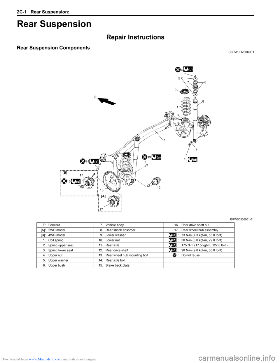
Rear Suspension ComponentsS6RW0D2306001
I6RW0D230001-01
F: Forward 7. Vehicle body 16. Rear drive shaft nut
[A]: 2WD model 8. Rear shock absorber 17. Rear wheel hub assembly
[B]: 4WD model 9. Lower washer : 73 N⋅m (7.3 kgf-m, 53.0 lb-ft)
1. Coil spring 10. Lower nut : 30 N⋅m (3.0 kgf-m, 22.0 lb-ft)
2. Spring upper seat 11. Rear axle : 175 N⋅m (17.5 kgf-m, 127.0 lb-ft)
3. Spring lower seat 12. Rear drive shaft : 90 N⋅m (9.0 kgf-m, 65.0 lb-ft)
4. Upper nut 13. Rear wheel hub mounting bolt : Do not reuse.
5. Upper washer 14. Rear axle bolt
6. Upper bush 15. Brake back plate