2006 SUZUKI SX4 light
[x] Cancel search: lightPage 1377 of 1556
Downloaded from www.Manualslib.com manuals search engine Wipers / Washers: 9D-3
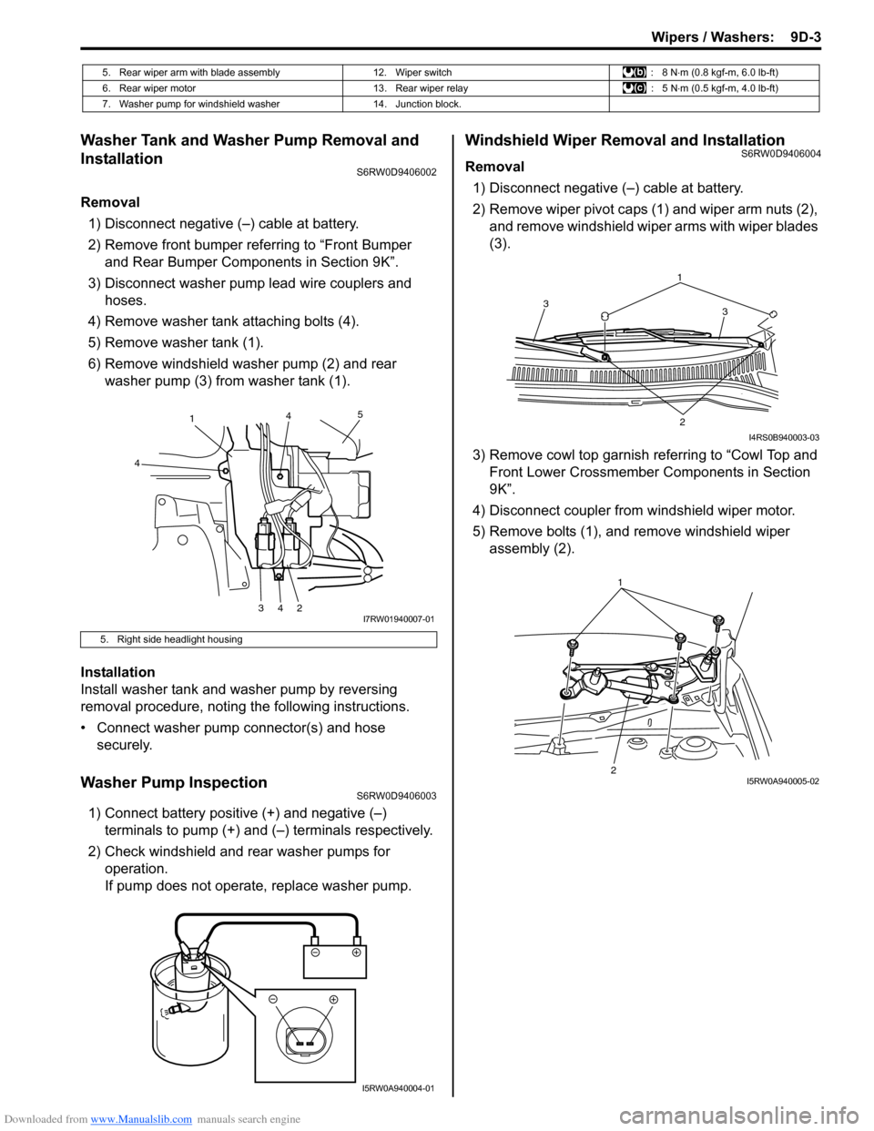
Washer Tank and Washer Pump Removal and
Installation
S6RW0D9406002
Removal
1) Disconnect negative (–) cable at battery.
2) Remove front bumper referring to “Front Bumper
and Rear Bumper Components in Section 9K”.
3) Disconnect washer pump lead wire couplers and
hoses.
4) Remove washer tank attaching bolts (4).
5) Remove washer tank (1).
6) Remove windshield washer pump (2) and rear
washer pump (3) from washer tank (1).
Installation
Install washer tank and washer pump by reversing
removal procedure, noting the following instructions.
• Connect washer pump connector(s) and hose
securely.
Washer Pump InspectionS6RW0D9406003
1) Connect battery positive (+) and negative (–)
terminals to pump (+) and (–) terminals respectively.
2) Check windshield and rear washer pumps for
operation.
If pump does not operate, replace washer pump.
Windshield Wiper Removal and InstallationS6RW0D9406004
Removal
1) Disconnect negative (–) cable at battery.
2) Remove wiper pivot caps (1) and wiper arm nuts (2),
and remove windshield wiper arms with wiper blades
(3).
3) Remove cowl top garnish referring to “Cowl Top and
Front Lower Crossmember Components in Section
9K”.
4) Disconnect coupler from windshield wiper motor.
5) Remove bolts (1), and remove windshield wiper
assembly (2).
5. Rear wiper arm with blade assembly 12. Wiper switch : 8 N⋅m (0.8 kgf-m, 6.0 lb-ft)
6. Rear wiper motor 13. Rear wiper relay : 5 N⋅m (0.5 kgf-m, 4.0 lb-ft)
7. Washer pump for windshield washer 14. Junction block.
5. Right side headlight housing
1
4
34245
I7RW01940007-01
I5RW0A940004-01
1
3 3
2
I4RS0B940003-03
21I5RW0A940005-02
Page 1382 of 1556
Downloaded from www.Manualslib.com manuals search engine 9D-8 Wipers / Washers:
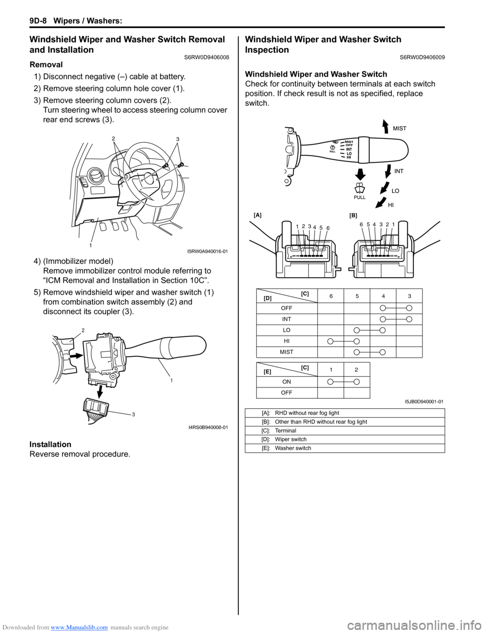
Windshield Wiper and Washer Switch Removal
and Installation
S6RW0D9406008
Removal
1) Disconnect negative (–) cable at battery.
2) Remove steering column hole cover (1).
3) Remove steering column covers (2).
Turn steering wheel to access steering column cover
rear end screws (3).
4) (Immobilizer model)
Remove immobilizer control module referring to
“ICM Removal and Installation in Section 10C”.
5) Remove windshield wiper and washer switch (1)
from combination switch assembly (2) and
disconnect its coupler (3).
Installation
Reverse removal procedure.
Windshield Wiper and Washer Switch
Inspection
S6RW0D9406009
Windshield Wiper and Washer Switch
Check for continuity between terminals at each switch
position. If check result is not as specified, replace
switch.
12
3I5RW0A940016-01
1 2
3
I4RS0B940008-01
[A]: RHD without rear fog light
[B]: Other than RHD without rear fog light
[C]: Terminal
[D]: Wiper switch
[E]: Washer switch
OFF
INT6543
MIST
OFF12
ONLO
HI
65432112
3
4
5
6 [A]
[B]
[C]
[D]
[E][C]
I5JB0D940001-01
Page 1383 of 1556
Downloaded from www.Manualslib.com manuals search engine Wipers / Washers: 9D-9
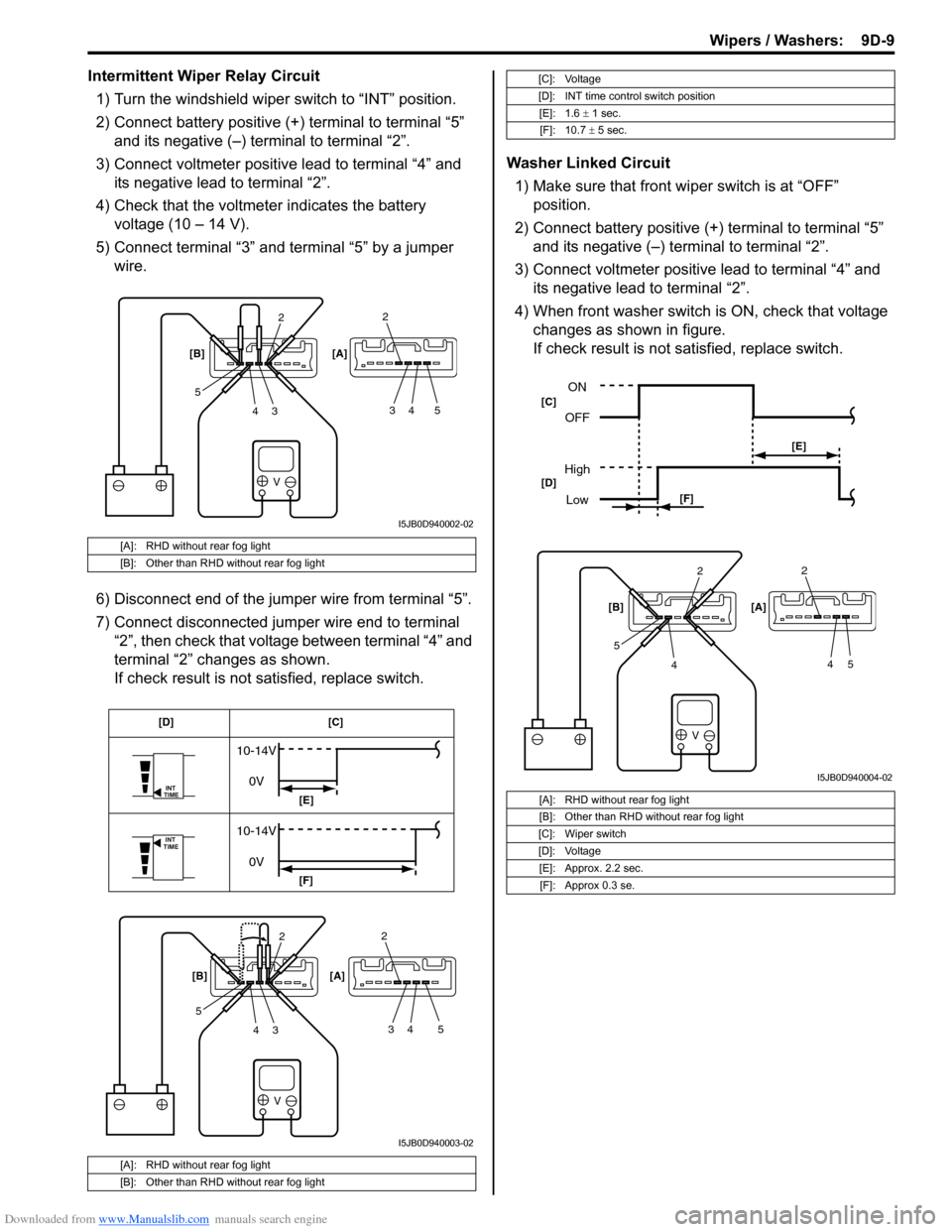
Intermittent Wiper Relay Circuit
1) Turn the windshield wiper switch to “INT” position.
2) Connect battery positive (+) terminal to terminal “5”
and its negative (–) terminal to terminal “2”.
3) Connect voltmeter positive lead to terminal “4” and
its negative lead to terminal “2”.
4) Check that the voltmeter indicates the battery
voltage (10 – 14 V).
5) Connect terminal “3” and terminal “5” by a jumper
wire.
6) Disconnect end of the jumper wire from terminal “5”.
7) Connect disconnected jumper wire end to terminal
“2”, then check that voltage between terminal “4” and
terminal “2” changes as shown.
If check result is not satisfied, replace switch.Washer Linked Circuit
1) Make sure that front wiper switch is at “OFF”
position.
2) Connect battery positive (+) terminal to terminal “5”
and its negative (–) terminal to terminal “2”.
3) Connect voltmeter positive lead to terminal “4” and
its negative lead to terminal “2”.
4) When front washer switch is ON, check that voltage
changes as shown in figure.
If check result is not satisfied, replace switch.
[A]: RHD without rear fog light
[B]: Other than RHD without rear fog light
[A]: RHD without rear fog light
[B]: Other than RHD without rear fog light
V
2
3 4 52
34 5 [B] [A]
I5JB0D940002-02
V
INT
TIME
INT
TIME
10-14V
0V
10-14V
0V
2
3 4 52
34 5 [B] [A][C] [D]
[E]
[F]
I5JB0D940003-02
[C]: Voltage
[D]: INT time control switch position
[E]: 1.6 ± 1 sec.
[F]: 10.7 ± 5 sec.
[A]: RHD without rear fog light
[B]: Other than RHD without rear fog light
[C]: Wiper switch
[D]: Voltage
[E]: Approx. 2.2 sec.
[F]: Approx 0.3 se.
V
2
4 52
45 [B] [A]
ON
OFF
High
Low
[E]
[F] [C]
[D]
I5JB0D940004-02
Page 1384 of 1556
Downloaded from www.Manualslib.com manuals search engine 9D-10 Wipers / Washers:
Rear Wiper and Washer Switch Removal and
Installation
S6RW0D9406010
For removal and installation, refer to “Windshield Wiper
and Washer Switch Removal and Installation”.
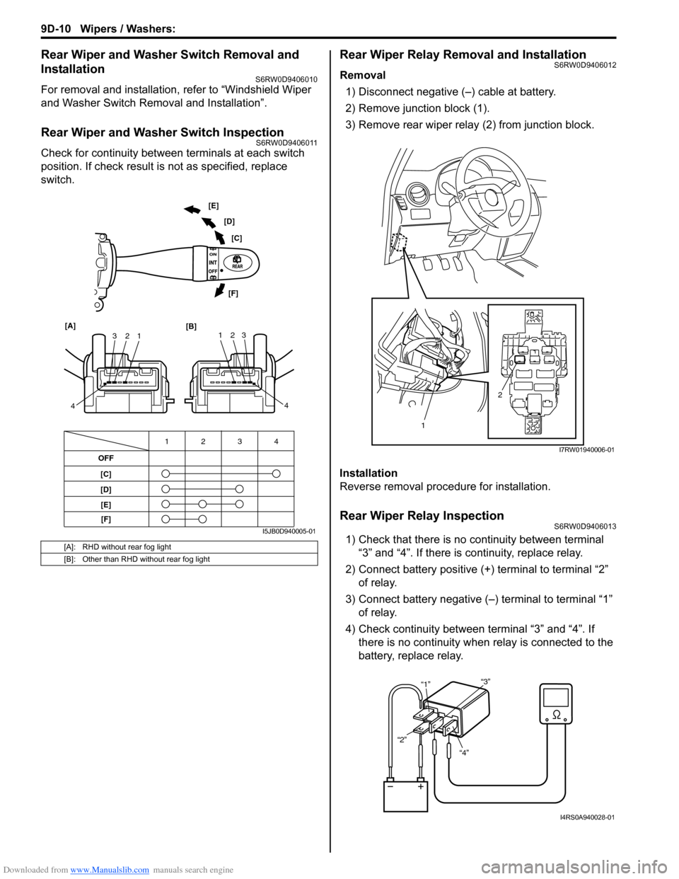
Rear Wiper and Washer Switch InspectionS6RW0D9406011
Check for continuity between terminals at each switch
position. If check result is not as specified, replace
switch.
Rear Wiper Relay Removal and InstallationS6RW0D9406012
Removal
1) Disconnect negative (–) cable at battery.
2) Remove junction block (1).
3) Remove rear wiper relay (2) from junction block.
Installation
Reverse removal procedure for installation.
Rear Wiper Relay InspectionS6RW0D9406013
1) Check that there is no continuity between terminal
“3” and “4”. If there is continuity, replace relay.
2) Connect battery positive (+) terminal to terminal “2”
of relay.
3) Connect battery negative (–) terminal to terminal “1”
of relay.
4) Check continuity between terminal “3” and “4”. If
there is no continuity when relay is connected to the
battery, replace relay.[A]: RHD without rear fog light
[B]: Other than RHD without rear fog light
OFF
[C]
[D]4 3 12
1 2 3
4 [A]
[B]123
4 [C] [D] [E]
[F]
[E]
[F]
I5JB0D940005-01
2
1
I7RW01940006-01
“4” “2”“1”“3”
I4RS0A940028-01
Page 1387 of 1556
Downloaded from www.Manualslib.com manuals search engine Glass / Windows / Mirrors: 9E-2
Schematic and Routing Diagram
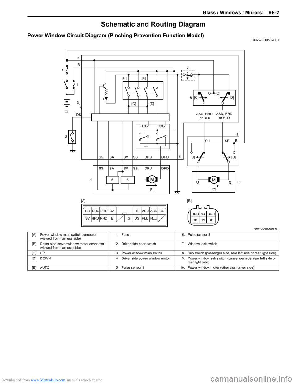
Power Window Circuit Diagram (Pinching Prevention Function Model)S6RW0D9502001
6 5
[C][D]
DSB IG
E
SG SV SBSA DRU DRD
SG SV SBSA DRU DRDASU, RRU
or RLUASD, RRD
or RLD
[C][C]
D U
[C][D]
SU SBB [C][D] [E] [E]
ESG
SV SB SADRU DRD B ASU ASD
RRU
RRDDS IG RLD RLUSG SV SBSA DRU DRD [A] [B] 1
1
3
2
47
8
9
10
I6RW0D950001-01
[A]: Power window main switch connector
(viewed from harness side)1. Fuse 6. Pulse sensor 2
[B]: Driver side power window motor connector
(viewed from harness side)2. Driver side door switch 7. Window lock switch
[C]: UP 3. Power window main switch 8. Sub switch (passenger side, rear left side or rear light side)
[D]: DOWN 4. Driver side power window motor 9. Power window sub switch (passenger side, rear left side or
rear light side)
[E]: AUTO 5. Pulse sensor 1 10. Power window motor (other than driver side)
Page 1394 of 1556
Downloaded from www.Manualslib.com manuals search engine 9E-9 Glass / Windows / Mirrors:
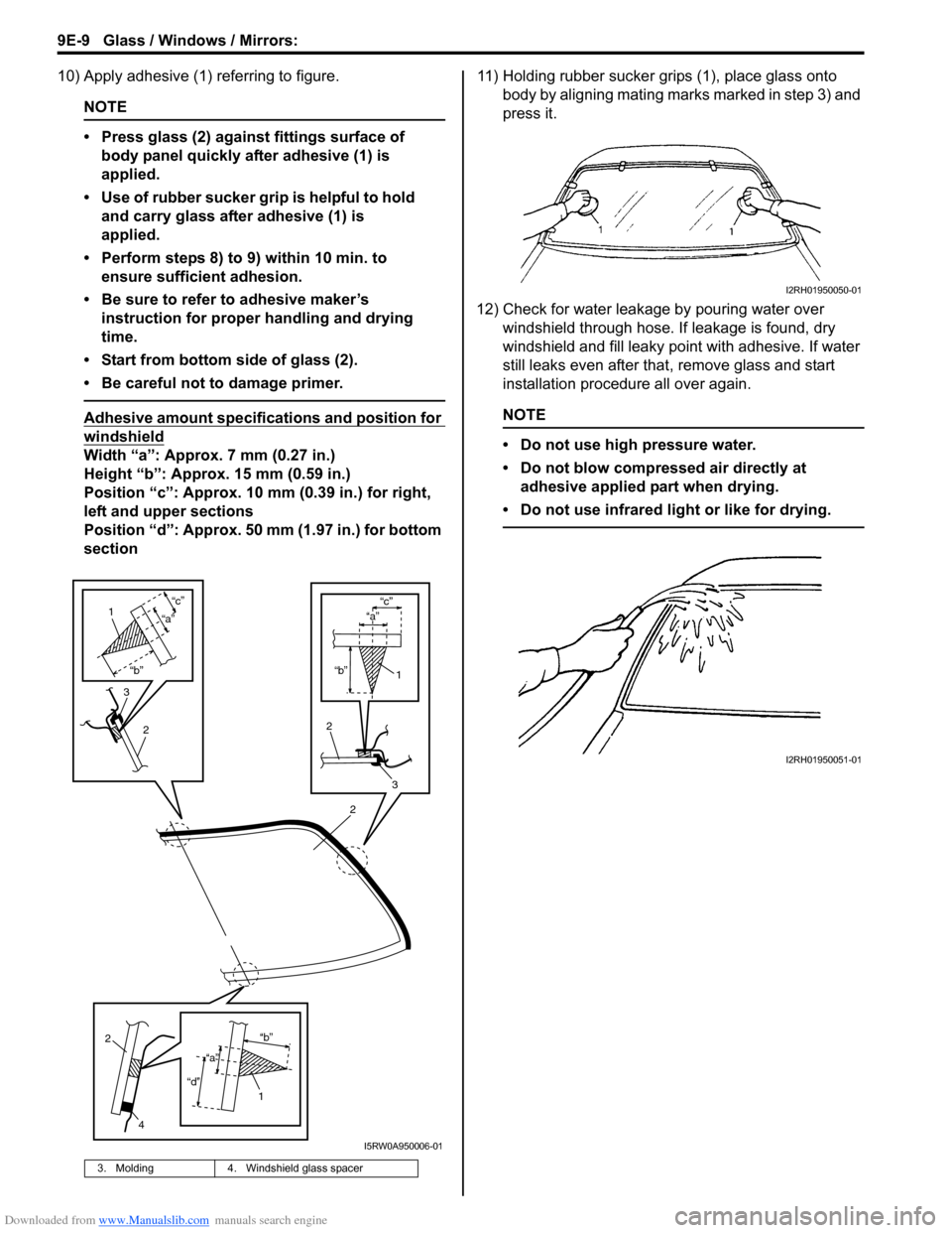
10) Apply adhesive (1) referring to figure.
NOTE
• Press glass (2) against fittings surface of
body panel quickly after adhesive (1) is
applied.
• Use of rubber sucker grip is helpful to hold
and carry glass after adhesive (1) is
applied.
• Perform steps 8) to 9) within 10 min. to
ensure sufficient adhesion.
• Be sure to refer to adhesive maker’s
instruction for proper handling and drying
time.
• Start from bottom side of glass (2).
• Be careful not to damage primer.
Adhesive amount specifications and position for
windshield
Width “a”: Approx. 7 mm (0.27 in.)
Height “b”: Approx. 15 mm (0.59 in.)
Position “c”: Approx. 10 mm (0.39 in.) for right,
left and upper sections
Position “d”: Approx. 50 mm (1.97 in.) for bottom
section11) Holding rubber sucker grips (1), place glass onto
body by aligning mating marks marked in step 3) and
press it.
12) Check for water leakage by pouring water over
windshield through hose. If leakage is found, dry
windshield and fill leaky point with adhesive. If water
still leaks even after that, remove glass and start
installation procedure all over again.
NOTE
• Do not use high pressure water.
• Do not blow compressed air directly at
adhesive applied part when drying.
• Do not use infrared light or like for drying.
3. Molding 4. Windshield glass spacer
2
“b”
“c”
2
3
1
“a”
3
2
1
“b”
“c”
“a”
2
4
1“b”
“d”
“a”
I5RW0A950006-01
I2RH01950050-01
I2RH01950051-01
Page 1415 of 1556
Downloaded from www.Manualslib.com manuals search engine Security and Locks: 9F-4
Keyless Entry System Symptom Diagnosis (If Equipped)S6RW0D9604003
NOTE
• Confirm that power door lock system is in good condition before referring to the following possible
causes.
• Check each part in the order from the top of the following list.
Condition Possible cause Correction / Reference Item
All door can not be locked
/ unlocked by only
keyless entry transmitterTransmitter battery deadReplace battery referring to “Replacement of
Transmitter Battery (Other than Keyless Start
Model)”.
Door switch faultyCheck door switch referring to “Door Switch
(Front / Rear Door) Inspection in Section 9C”
and/or “Rear End Door Switch Inspection in
Section 9C”.
Transmitter faultyReplace transmitter.
Key reminder switch in ignition switch
faultyCheck ignition switch referring to “Ignition
Switch Inspection in Section 9C”.
Wiring or grounding faultyRepair circuit.
Keyless entry receiver faultyCheck keyless entry receiver referring to
“Keyless Entry Receiver and Its Circuit
Inspection (If Equipped)”.
BCM faultyReplace after making sure that none of above
parts is faulty.
Turn signal lights can not
be flashed when doors
are locked / unlocked by
keyless entry transmitterTurn signal and hazard warning relay
faultyCheck turn signal and hazard warning relay
referring to “Turn Signal and Hazard Warning
Relay Inspection in Section 9B”.
Wiring or grounding faultyRepair circuit.
BCM faultyReplace after making sure that none of above
parts is faulty.
Interior light does not
light when doors are
unlocked by keyless entry
transmitterWiring or grounding faultyRepair circuit.
BCM faultyReplace after making sure that none of above
parts is faulty.
Hazard warning lights do
not light when doors are
locked/unlocked by
keyless entry transmitterTurn signal and hazard warning relay
faultyCheck turn signal and hazard warning relay
referring to “Turn Signal and Hazard Warning
Relay Inspection in Section 9B”.
Wiring or grounding faultyRepair circuit.
BCM faultyReplace after making sure that none of above
parts is faulty.
Transmitter code can not
be programmed to BCMDoor switch faultyCheck door switch referring to “Door Switch
(Front / Rear Door) Inspection in Section 9C”
and/or “Rear End Door Switch Inspection in
Section 9C”.
Keyless entry receiver faultyCheck keyless entry receiver referring to
“Keyless Entry Receiver and Its Circuit
Inspection (If Equipped)”.
Key reminder switch in ignition switch
faultyCheck ignition switch referring to “Ignition
Switch Inspection in Section 9C”.
Wiring or grounding faultyRepair circuit.
BCM faultyReplace after making sure that none of above
parts is faulty.
Page 1416 of 1556
Downloaded from www.Manualslib.com manuals search engine 9F-5 Security and Locks:
Keyless Entry System Operation Inspection (If
Equipped)
S6RW0D9604004
NOTE
When performing the this inspection, make
sure to have any of the door once opened /
closed after the ignition key has been
removed from the ignition key cylinder.
1) Confirm that power door lock system operates
normally, refer to “Power Door Lock System
Operation Inspection (If Equipped)”.
2) All doors are closed and unlocked.
3) Check the following operation:
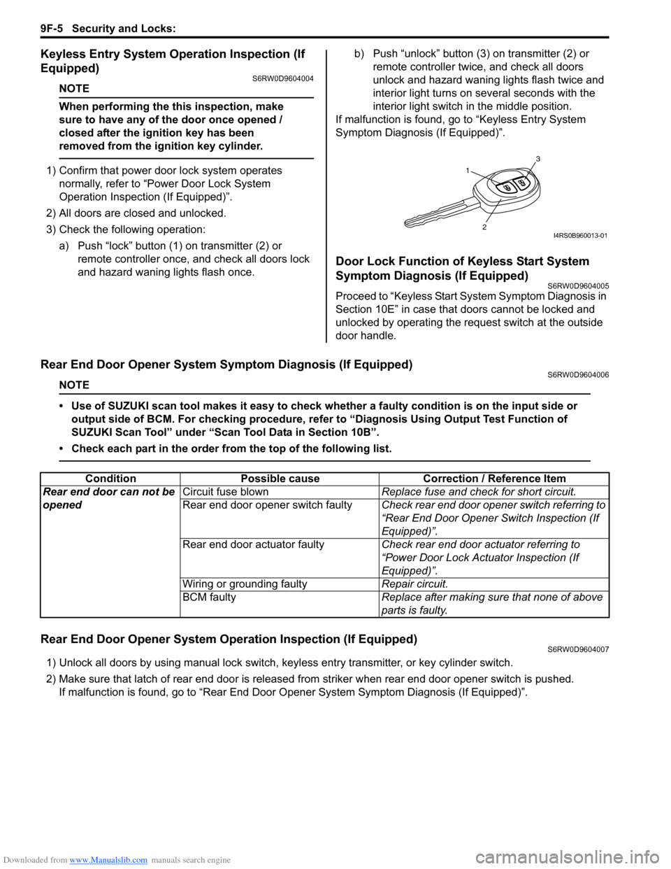
a) Push “lock” button (1) on transmitter (2) or
remote controller once, and check all doors lock
and hazard waning lights flash once.b) Push “unlock” button (3) on transmitter (2) or
remote controller twice, and check all doors
unlock and hazard waning lights flash twice and
interior light turns on several seconds with the
interior light switch in the middle position.
If malfunction is found, go to “Keyless Entry System
Symptom Diagnosis (If Equipped)”.
Door Lock Function of Keyless Start System
Symptom Diagnosis (If Equipped)
S6RW0D9604005
Proceed to “Keyless Start System Symptom Diagnosis in
Section 10E” in case that doors cannot be locked and
unlocked by operating the request switch at the outside
door handle.
Rear End Door Opener System Symptom Diagnosis (If Equipped)S6RW0D9604006
NOTE
• Use of SUZUKI scan tool makes it easy to check whether a faulty condition is on the input side or
output side of BCM. For checking procedure, refer to “Diagnosis Using Output Test Function of
SUZUKI Scan Tool” under “Scan Tool Data in Section 10B”.
• Check each part in the order from the top of the following list.
Rear End Door Opener System Operation Inspection (If Equipped)S6RW0D9604007
1) Unlock all doors by using manual lock switch, keyless entry transmitter, or key cylinder switch.
2) Make sure that latch of rear end door is released from striker when rear end door opener switch is pushed.
If malfunction is found, go to “Rear End Door Opener System Symptom Diagnosis (If Equipped)”.
1
3
2I4RS0B960013-01
Condition Possible cause Correction / Reference Item
Rear end door can not be
openedCircuit fuse blownReplace fuse and check for short circuit.
Rear end door opener switch faultyCheck rear end door opener switch referring to
“Rear End Door Opener Switch Inspection (If
Equipped)”.
Rear end door actuator faultyCheck rear end door actuator referring to
“Power Door Lock Actuator Inspection (If
Equipped)”.
Wiring or grounding faultyRepair circuit.
BCM faultyReplace after making sure that none of above
parts is faulty.