2006 SUZUKI SX4 Throttle fuse
[x] Cancel search: Throttle fusePage 398 of 1556

Downloaded from www.Manualslib.com manuals search engine 1H-3 Ignition System:
Component Location
Ignition System Components LocationS6RW0D1803001
NOTE
The figure shows left-hand steering vehicle. For right-hand steering vehicle, parts with (*) are installed
at the opposite side.
12*
15*
13
1 689
11
10
74
5
14
2 3
16
I5RW0C180002-01
1. ECM 7. ECT sensor 13. Battery fuse box
2. Ignition coil assembly for No.1 and No.4 spark plugs 8. MAF and IAT sensor 14. Relay box
3. Ignition coil assembly for No.2 and No.3 spark plugs 9. Electric throttle body assembly 15. Junction block assembly
4. CMP sensor (VVT model) 10. High-tension cords 16. CMP sensor (VVT model)
5. CKP sensor 11. Knock sensor
6. MAP sensor (if equipped) 12. Data link connector
Page 407 of 1556

Downloaded from www.Manualslib.com manuals search engine Starting System: 1I-2
Condition Possible cause Correction / Reference Item
Motor not running (No
operating sound of
magnetic switch)Transmission range sensor is not in P or
N, or not adjusted (A/T model)Shift in P or N, or adjust sensor. (A/T model)
Battery run downRecharge battery.
Battery voltage too low due to battery
deteriorationReplace battery.
Poor contact in battery terminal
connectionRetighten or replace.
Loose grounding cable connectionRetighten.
Fuse set loose or blown offTighten or replace.
Poor contacting action of ignition switch
and magnetic switchReplace.
Lead wire coupler loose in placeRetighten.
Open-circuit between ignition switch and
magnetic switchRepair.
Open-circuit in pull-in coilReplace magnetic switch.
Brushes are seating poorly or worn
downRepair or replace.
Poor sliding of plunger and/or pinionRepair.
Faulty starting motor control relay“Main Relay, Fuel Pump Relay, Starting Motor
Control Relay, Throttle Actuator Control Relay
and Radiator Cooling Fan Relay Inspection in
Section 1C”.
Faulty ECM and its circuit“Inspection of ECM and Its Circuits in Section
1A”.
Motor not running
(Operating sound of
magnetic switch heard)Battery run downRecharge battery.
Battery voltage too low due to battery
deteriorationReplace battery.
Loose battery cable connectionsRetighten.
Burnt main contact point, or poor
contacting action of magnetic switchReplace magnetic switch.
Brushes are seating poorly or worn
downRepair or replace.
Weakened brush springReplace.
Burnt commutatorReplace armature.
Layer short-circuit of armatureReplace.
Crankshaft rotation obstructedRepair.
Starting motor running
but too slow (small
torque) (If battery and
wiring are satisfactory,
inspect starting motor)Insufficient contact of magnetic switch
main contactsReplace magnetic switch.
Layer short-circuit of armatureReplace.
Disconnected, burnt or worn
commutatorRepair commutator or replace armature.
Worn brushesReplace brush.
Weakened brush springsReplace spring.
Burnt or abnormally worn end bushReplace bush.
Starting motor running,
but not cranking engineWorn pinion tipReplace over-running clutch.
Poor sliding of over-running clutchRepair.
Over-running clutch slippingReplace over-running clutch.
Worn teeth of ring gearReplace flywheel (M/T model) or drive plate (A/
T model).
NoiseAbnormally worn bushReplace bush.
Worn pinion or worn teeth of ring gearReplace over-running clutch, flywheel (M/T
model) or drive plate (A/T model).
Poor sliding of pinion (failure in return
movement)Repair or replace.
Worn internal or planetary gear teethReplace.
Lack of oil in each partLubricate.
Page 666 of 1556

Downloaded from www.Manualslib.com manuals search engine 5A-18 Automatic Transmission/Transaxle:
Step 2. DTC / Freeze Frame Data Check, Record and
Clearance
First, referring to “DTC Check”, check DTC and pending
DTC. If DTC exists, print or write down DTC and freeze
frame data and then clear malfunction DTC(s) by
referring to “DTC Clearance”. Malfunction DTC indicates
malfunction in the system but it is not possible to know
from it whether the malfunction is occurring now or it
occurred in the past and normal condition has been
restored. In order to know that, check symptom in
question according to Step 5 and then recheck DTC
according to Step 6.
Diagnosing a trouble based on the DTC in this step only
or failure to clear the DTC in this step may result in an
faulty diagnosis, trouble diagnosis of a normal circuit or
difficulty in troubleshooting which is otherwise
unnecessary.
Step 3 and 4. Visual Inspection
As a preliminary step, be sure to perform visual check of
the items that support proper function of the engine and
automatic transaxle referring to “Visual Inspection”.
Step 5. Trouble Symptom Confirmation
Check trouble symptoms based on information obtained
in “Step 1. Customer Complaint Analysis: ” and “Step 2.
DTC / Freeze Frame Data Check, Record and
Clearance: ”.
Also, reconfirm DTC according to “DTC Confirmation
Procedure” described in each DTC flow.
Step 6 and 7. Rechecking and Record of DTC and
Freeze Frame Data
Refer to “DTC Check” for checking procedure.Step 8. A/T Basic Check and A/T Symptom
Diagnosis
Perform basic check of A/T according to “A/T Basic
Check” first. When the end of the flow has been reached,
check the parts of the system suspected as a possible
cause referring to “A/T Symptom Diagnosis” and based
on symptoms appearing on the vehicle (symptoms
obtained through steps of customer complaint analysis,
trouble symptom confirmation and/or A/T basic check)
and repair or replace faulty parts, if any.
Step 9. Troubleshooting for DTC
Based on the DTC indicated in Step 6 / 7 and referring to
“applicable DTC flow”, locate the cause of the trouble,
namely in a sensor, switch, wire harness, connector,
actuator, TCM or other part and repair or replace faulty
parts.
Step 10. Check for Intermittent Problem
Check parts where an intermittent trouble is easy to
occur (e.g. wire harness, connector, etc.), referring to
“Intermittent and Poor Connection Inspection in Section
00” and related circuit of DTC recorded in Step 2.
Step 11. Final Confirmation Test
Confirm that the problem symptom has gone and the
vehicle is free from any abnormal conditions. If what has
been repaired is related to the malfunction DTC, clear
the DTC once and check to ensure that no malfunction
DTC is indicated.
Visual InspectionS6RW0D5104002
Visually check the following parts and systems.
Inspection item Referring
• A/T fluid ----- level, leakage, color “Automatic Transaxle Fluid Level Inspection in
Section 0B”
• A/T fluid hoses ----- disconnection, looseness, deterioration “A/T Fluid Cooler Hoses Replacement”
• Throttle cable (if equipped) ----- play (under warm engine),
installation
• A/T select cable ----- installation “Select Cable Removal and Installation”
• Engine oil ----- level, leakage “Engine Oil and Filter Change in Section 0B”
• Engine coolant ----- level, leakage “Engine Coolant Change in Section 0B”
• Engine mountings ----- play, looseness, damage “Engine Assembly Removal and Installation in
Section 1D”
• Suspension ----- play, looseness “Suspension, Wheels and Tires Symptom
Diagnosis in Section 2A”
• Drive shafts ----- damage “Front Drive Shaft Assembly On-Vehicle Inspection
in Section 3A”
• Battery ----- indicator condition, corrosion of terminal “Battery Inspection in Section 1J”
• Connectors of electric wire harness ----- disconnection, friction “Electronic Shift Control System Components
Location”
• Fuses ----- burning
• Parts ----- installation, damage
• Bolts ----- looseness
• Other parts that can be checked visually
Page 1179 of 1556
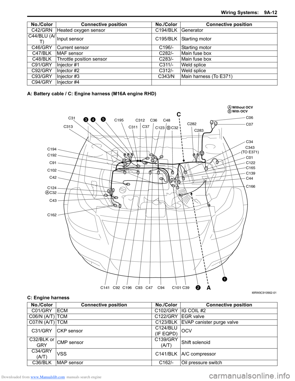
Downloaded from www.Manualslib.com manuals search engine Wiring Systems: 9A-12
A: Battery cable / C: Engine harness (M16A engine RHD)
C: Engine harnessC42/GRN Heated oxygen sensor C194/BLK Generator
C44/BLU (A/
T)Input sensor C195/BLK Starting motor
C46/GRY Current sensor C196/- Starting motor
C47/BLK MAF sensor C282/- Main fuse box
C48/BLK Throttle position sensor C283/- Main fuse box
C91/GRY Injector #1 C311/- Weld splice
C92/GRY Injector #2 C312/- Weld splice
C93/GRY Injector #3 C343/N Main harness (To E371)
C94/GRY Injector #4 No./Color Connective position No./Color Connective position
C124
C32
C42
C102
C91
C192
C194
C43
C162
C141C196
C195
C93C94C101C39C92
C31
C311C313C312
C36C48
C37C123
C47C32C282
C283
C343
(TO E371)
C01
C34
C07
C06
C122
C165
C139
C44
C166
43
2
1
5C
A
Without OCV
With OCV A
A
B
B
I6RW0C910902-01
No./Color Connective position No./Color Connective position
C01/GRY ECM C102/GRY IG COIL #2
C06/N (A/T) TCM C122/GRY EGR valve
C07/N (A/T) TCM C123/BLK EVAP canister purge valve
C31/GRY CKP sensorC124/BLU
(IF EQPD)OCV
C32/BLK or
GRYCMP sensorC139/GRY
(A/T)Shift solenoid
C34/GRY
(A/T)VSS C141/BLK A/C compressor
C36/BLK MAP sensor C162/- Oil pressure switch
Page 1180 of 1556
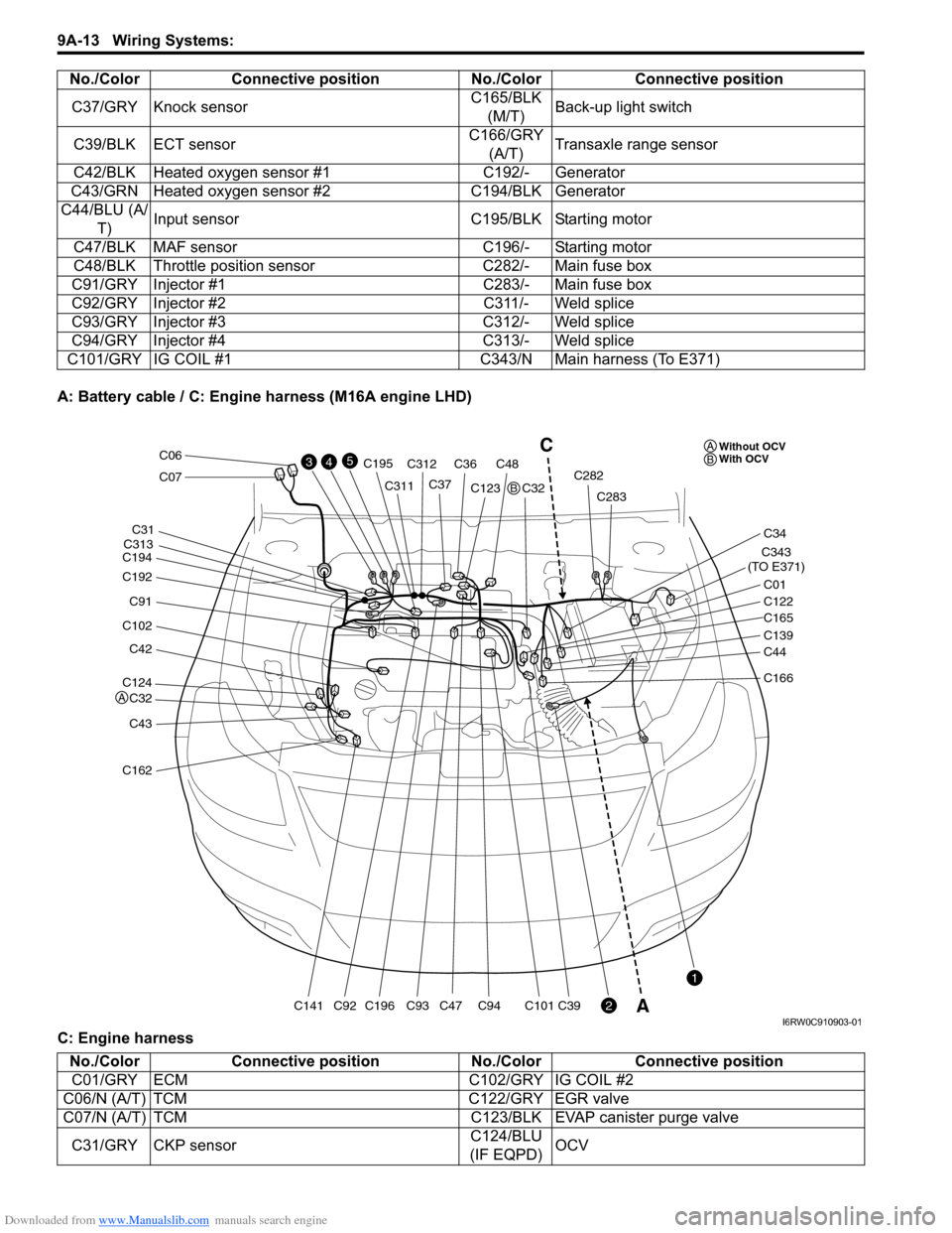
Downloaded from www.Manualslib.com manuals search engine 9A-13 Wiring Systems:
A: Battery cable / C: Engine harness (M16A engine LHD)
C: Engine harnessC37/GRY Knock sensorC165/BLK
(M/T)Back-up light switch
C39/BLK ECT sensorC166/GRY
(A/T)Transaxle range sensor
C42/BLK Heated oxygen sensor #1 C192/- Generator
C43/GRN Heated oxygen sensor #2 C194/BLK Generator
C44/BLU (A/
T)Input sensor C195/BLK Starting motor
C47/BLK MAF sensor C196/- Starting motor
C48/BLK Throttle position sensor C282/- Main fuse box
C91/GRY Injector #1 C283/- Main fuse box
C92/GRY Injector #2 C311/- Weld splice
C93/GRY Injector #3 C312/- Weld splice
C94/GRY Injector #4 C313/- Weld splice
C101/GRY IG COIL #1 C343/N Main harness (To E371)No./Color Connective position No./Color Connective position
C124
C32
C42
C102
C91
C192
C194
C43
C162
C141C196
C195
C93C94C101C39C92
C31
C311
C313C312
C36C48
C37C123
C47C32C282
C283
C343
(TO E371)
C01
C34
C07
C06
C122
C165
C139
C44
C166
43
2
1
5C
AWithout OCV
With OCV A
A
B
B
I6RW0C910903-01
No./Color Connective position No./Color Connective position
C01/GRY ECM C102/GRY IG COIL #2
C06/N (A/T) TCM C122/GRY EGR valve
C07/N (A/T) TCM C123/BLK EVAP canister purge valve
C31/GRY CKP sensorC124/BLU
(IF EQPD)OCV
Page 1181 of 1556
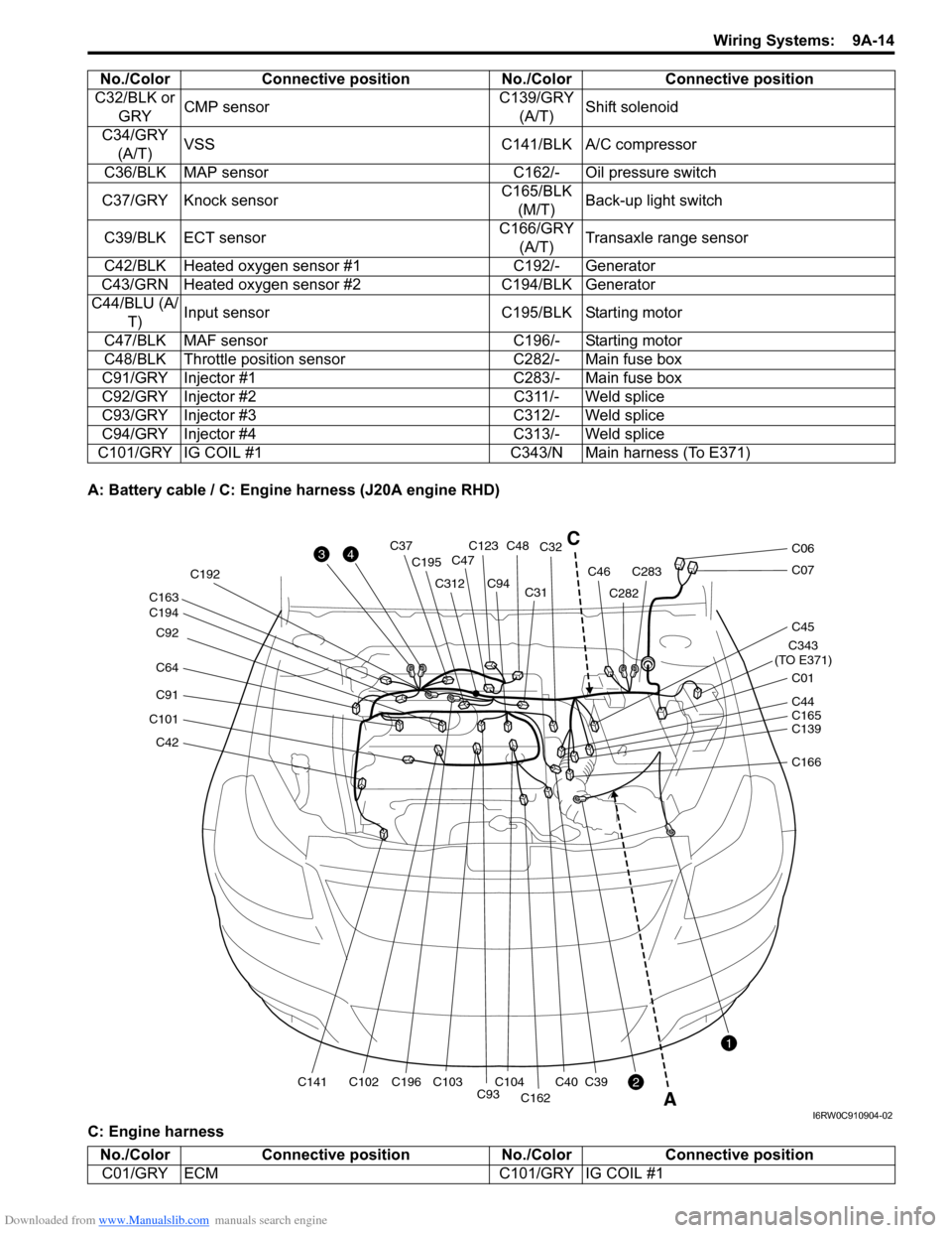
Downloaded from www.Manualslib.com manuals search engine Wiring Systems: 9A-14
A: Battery cable / C: Engine harness (J20A engine RHD)
C: Engine harnessC32/BLK or
GRYCMP sensorC139/GRY
(A/T)Shift solenoid
C34/GRY
(A/T)VSS C141/BLK A/C compressor
C36/BLK MAP sensor C162/- Oil pressure switch
C37/GRY Knock sensorC165/BLK
(M/T)Back-up light switch
C39/BLK ECT sensorC166/GRY
(A/T)Transaxle range sensor
C42/BLK Heated oxygen sensor #1 C192/- Generator
C43/GRN Heated oxygen sensor #2 C194/BLK Generator
C44/BLU (A/
T)Input sensor C195/BLK Starting motor
C47/BLK MAF sensor C196/- Starting motor
C48/BLK Throttle position sensor C282/- Main fuse box
C91/GRY Injector #1 C283/- Main fuse box
C92/GRY Injector #2 C311/- Weld splice
C93/GRY Injector #3 C312/- Weld splice
C94/GRY Injector #4 C313/- Weld splice
C101/GRY IG COIL #1 C343/N Main harness (To E371)No./Color Connective position No./Color Connective position
C42
C101
C91
C64 C92
C194 C163
C141C102C196 C192
C195
C312
C93C104C103
C94C31C32
C40
C162
C39
C123C48C37
C47
C282
C283C46
C343
(TO E371)
C01
C45
C07
C06
C139 C44
C165
C166
3
2
1
4
A
C
I6RW0C910904-02
No./Color Connective position No./Color Connective position
C01/GRY ECM C101/GRY IG COIL #1
Page 1182 of 1556
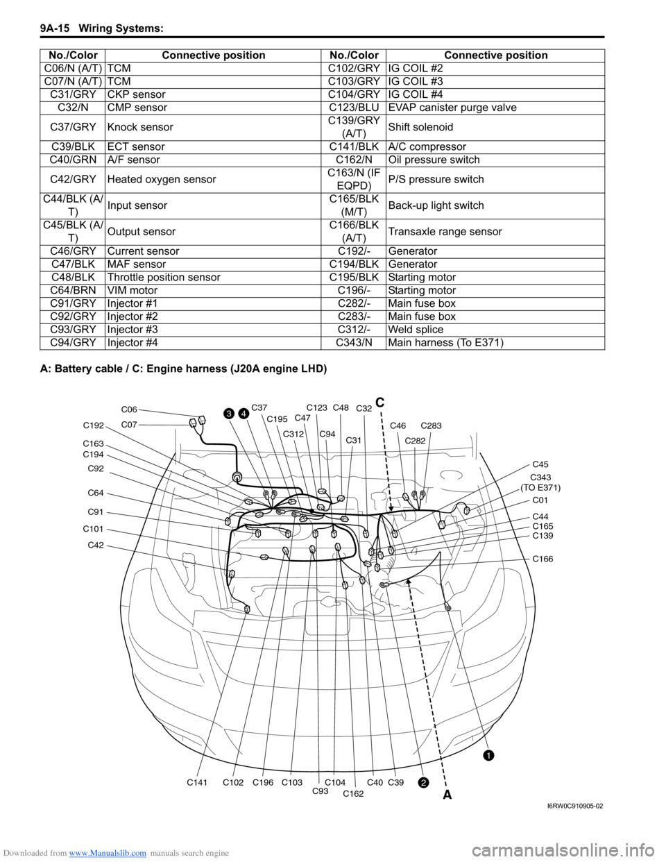
Downloaded from www.Manualslib.com manuals search engine 9A-15 Wiring Systems:
A: Battery cable / C: Engine harness (J20A engine LHD)C06/N (A/T) TCM C102/GRY IG COIL #2
C07/N (A/T) TCM C103/GRY IG COIL #3
C31/GRY CKP sensor C104/GRY IG COIL #4
C32/N CMP sensor C123/BLU EVAP canister purge valve
C37/GRY Knock sensorC139/GRY
(A/T)Shift solenoid
C39/BLK ECT sensor C141/BLK A/C compressor
C40/GRN A/F sensor C162/N Oil pressure switch
C42/GRY Heated oxygen sensorC163/N (IF
EQPD)P/S pressure switch
C44/BLK (A/
T)Input sensorC165/BLK
(M/T)Back-up light switch
C45/BLK (A/
T)Output sensorC166/BLK
(A/T)Transaxle range sensor
C46/GRY Current sensor C192/- Generator
C47/BLK MAF sensor C194/BLK Generator
C48/BLK Throttle position sensor C195/BLK Starting motor
C64/BRN VIM motor C196/- Starting motor
C91/GRY Injector #1 C282/- Main fuse box
C92/GRY Injector #2 C283/- Main fuse box
C93/GRY Injector #3 C312/- Weld splice
C94/GRY Injector #4 C343/N Main harness (To E371) No./Color Connective position No./Color Connective position
C42
C101
C91
C64 C92
C194 C163
C141C102C196 C192
C195
C312
C93C104C103
C94C31C32
C40
C162
C39
C123C48C37
C47
C282
C283C46
C343
(TO E371)
C01
C45
C07
C06
C139 C44
C165
C166
3
2
1
4C
A
I6RW0C910905-02
Page 1183 of 1556
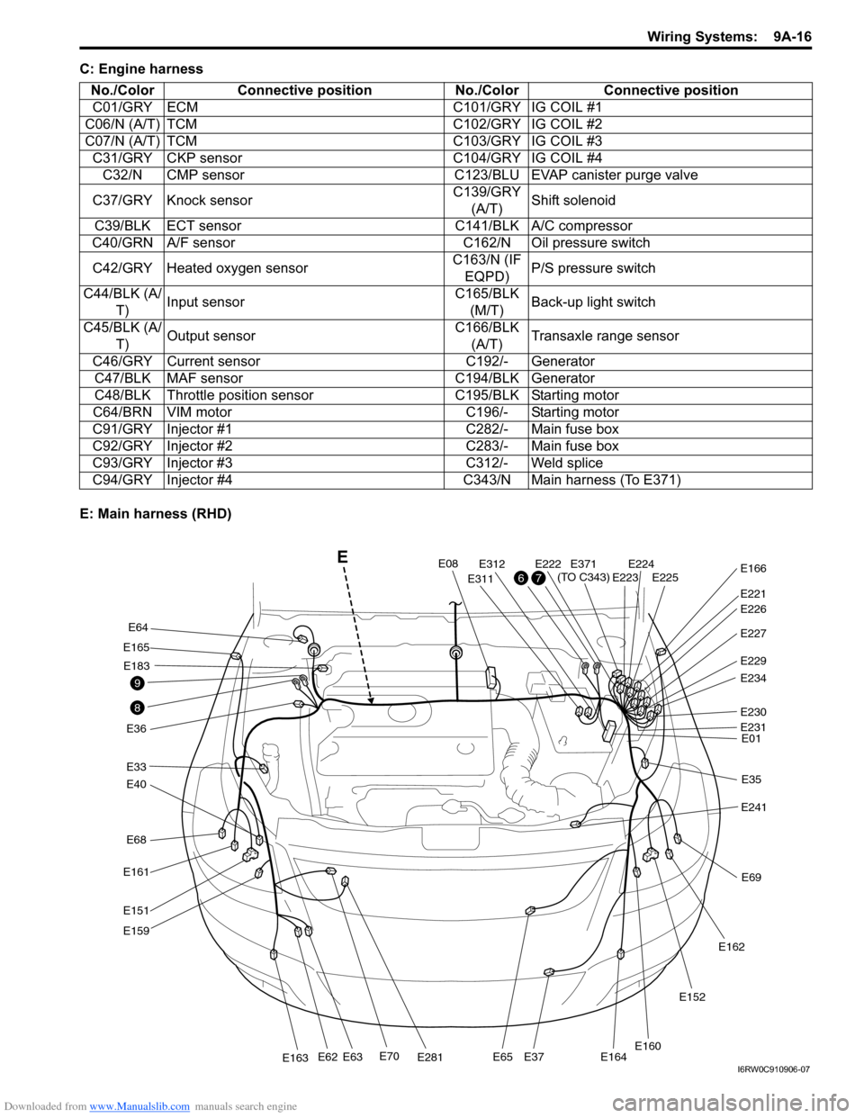
Downloaded from www.Manualslib.com manuals search engine Wiring Systems: 9A-16
C: Engine harness
E: Main harness (RHD)No./Color Connective position No./Color Connective position
C01/GRY ECM C101/GRY IG COIL #1
C06/N (A/T) TCM C102/GRY IG COIL #2
C07/N (A/T) TCM C103/GRY IG COIL #3
C31/GRY CKP sensor C104/GRY IG COIL #4
C32/N CMP sensor C123/BLU EVAP canister purge valve
C37/GRY Knock sensorC139/GRY
(A/T)Shift solenoid
C39/BLK ECT sensor C141/BLK A/C compressor
C40/GRN A/F sensor C162/N Oil pressure switch
C42/GRY Heated oxygen sensorC163/N (IF
EQPD)P/S pressure switch
C44/BLK (A/
T)Input sensorC165/BLK
(M/T)Back-up light switch
C45/BLK (A/
T)Output sensorC166/BLK
(A/T)Transaxle range sensor
C46/GRY Current sensor C192/- Generator
C47/BLK MAF sensor C194/BLK Generator
C48/BLK Throttle position sensor C195/BLK Starting motor
C64/BRN VIM motor C196/- Starting motor
C91/GRY Injector #1 C282/- Main fuse box
C92/GRY Injector #2 C283/- Main fuse box
C93/GRY Injector #3 C312/- Weld splice
C94/GRY Injector #4 C343/N Main harness (To E371)
E68
E40
E33
E165
E36
E161
E151
E159
E70E281E163E62E63E65E37E164
E64
E183
E08
E311
E312E222E224E225E223
E221
E371
(TO C343)E166
E227
E229
E234
E230
E01
E35
E241
E69
E162
E152
E160
E231
E226
8
9
76
E
I6RW0C910906-07