2006 SUZUKI SX4 Service wire
[x] Cancel search: Service wirePage 498 of 1556

Downloaded from www.Manualslib.com manuals search engine 3B-1 Differential:
Driveline / Axle
Differential
Precautions
Precaution for Rear Differential Oil LeakageS6RW0D3200001
Whenever vehicle is hoisted for any other service work than oil change, also be sure to check for oil leakage.
Precautions in Diagnosing TroubleS6RW0D3200002
• Do not disconnect the following parts before confirming diagnostic information (DTC, etc.) stored in 4WD control
module memory. These actions will erase memorized information in 4WD control module memory.
– Disconnection of coupler from 4WD control module
– Disconnection of battery cable from battery
– Disconnection of ground wire harness of 4WD control module
– Disconnect main fuse from fuse box
• Diagnostic information stored in 4WD control module memory can be cleared as well as checked by using SUZUKI
scan tool. Before using scan tool, read its Operator’s (Instruction) Manual carefully to have good understanding as
to what functions are available and how to use it.
• Be sure to read “Precautions for Electrical Circuit Service:” before inspection and observe what is written there.
Page 649 of 1556

Downloaded from www.Manualslib.com manuals search engine Automatic Transmission/Transaxle: 5A-1
Transmission / Transaxle
Automatic Transmission/Transaxle
Precautions
Precautions in Diagnosing TroubleS6RW0D5100001
• Do not disconnect couplers from TCM, battery cable
from battery, TCM ground wire harness from engine or
main fuse before checking the diagnostic information
(DTC, freeze frame data, etc.) stored in TCM memory.
Such disconnection will clear memorized information
in TCM memory.
• Diagnostic information stored in TCM memory can be
cleared as well as checked by using SUZUKI scan
tool or CAN communication OBD generic scan tool.
Before using scan tool, read its Operator’s
(Instruction) Manual carefully to have good
understanding as to what functions are available and
how to use it.
It is indistinguishable which module turns on MIL
because not only ECM but also TCM turns on MIL.
Therefore, check both ECM and TCM for DTC when
MIL lights on.
When checking TCM for DTC, keep in mind that DTC
is displayed on the scan tool as follows depending on
the scan tool used.
– SUZUKI scan tool displays DTC detected by TCM.
– CAN communication OBD generic scan tool
displays DTC detected by each of ECM and TCM
simultaneously.
• Be sure to read “Precautions for Electrical Circuit
Service in Section 00” before inspection and observe
what is written there.
• TCM replacement
– When substituting a known-good TCM, check that
all relays and actuators have resistance of
specified value.
Neglecting this check may result in damage to good
TCM.
• Communication of ECM, BCM, combination meter,
keyless start control module (if equipped), ABS
control module, 4WD control module (if equipped),
TCM and DLC, is established by CAN (Controller
Area Network). (For more detail of CAN
communication for ECM, refer to “CAN
Communication System Description”). Therefore,
handle CAN communication line with care referring to
“Precaution for CAN Communication System in
Section 00”.
Precautions for Disassembly and ReassemblyS6RW0D5100002
When repairing automatic transaxle, it is necessary to
conduct the on-vehicle test to investigate where the
cause of the trouble lies first.
Then whether overhaul should be done or not is
determined. If the transaxle is disassembled without
such preliminary procedure, not only the cause of the
trouble would be unknown, but also a secondary trouble
may occur and often time would be wasted.
As the automatic transaxle consists of high precision
component, the following cautions should be strictly
observed when handling its parts in disassembly and
reassembly.
• Disassembling valve body assembly is prohibited
essentially. However, a few parts can be
disassembled. When disassembling valve body
component parts, confirm whether their parts are
allowed to disassemble or not referring to “Valve Body
Assembly Disassembly and Reassembly”.
• When component part of forward clutch, direct clutch,
2nd brake and/or O/D and 2nd coast brake, namely
clutch disc, brake disc, retaining plate and/or
separator plate, have been replaced, all learned
contents, which have been stored in TCM memory by
executing learning control, should be initialized
referring to “Learning Control Initialization”.
• Make sure to wash dirt off from the transaxle so that
no such dirt will enter the transaxle during
dismounting and remounting.
• Select a clean place free from dust and dirt for
overhauling.
• Place a rubber mat on the work bench to protect parts
from damage.
• Work gloves or shop cloth should not be used. (Use a
nylon cloth or a paper towel.)
• When separating the case joint, do not pry with a
screwdriver or such but tap with a plastic hammer
lightly.
• Make sure to wash dirt off from the transaxle so that
no such dirt will enter the transaxle during
disassembly and reassembly.
• Wash the disassembled parts in ATF (Automatic
Transaxle Fluid) or kerosene (using care not to allow
ATF or kerosene to get on your face, etc.) and confirm
that each fluid passage is not clogged by blowing air
into it. But use kerosene to wash the discs, resin
washers and rubber parts.
• Replace each gasket, oil seal and O-ring with a new
one.
• Apply ATF to sliding or rotating parts before
reassembly.
Page 938 of 1556

Downloaded from www.Manualslib.com manuals search engine 7A-10 Heater and Ventilation:
Installation
Reverse removal procedure noting the following
instruction.
• Be sure to insert the linkage rod (1) into the hole (2) of
air intake control actuator.Air Intake Control Actuator InspectionS6RW0D7106013
Check air intake control actuator as follows:
1) Using service wire, connect battery positive terminal
to “d” terminal and battery negative terminal to
terminal “a”. And, check if air intake selector link
operates smoothly and it stops at “FRE” position (1).
2) Using service wire, connect battery positive terminal
to “d” terminal and battery negative terminal to
terminal “c”. And, check if air intake selector link
operates smoothly and it stops at “REC” position (2).
3) For auto A/C model, using service wire, connect
battery positive terminal to “d” terminal and battery
negative terminal to “b” terminal. And, check air
intake selector link operates smoothly and it stops at
MIX position (3).
If malfunction is found, replace air intake control
actuator.
21
I7RW01710017-02
4. Motor rotation direction
“a” “b” “c” “d”
1 3
2
4“a”
“b”
“c” “d”
I7RW01710018-05
Page 1025 of 1556

Downloaded from www.Manualslib.com manuals search engine Air Conditioning System: Automatic Type 7B-85
Blower Motor Controller InspectionS6RW0D7226012
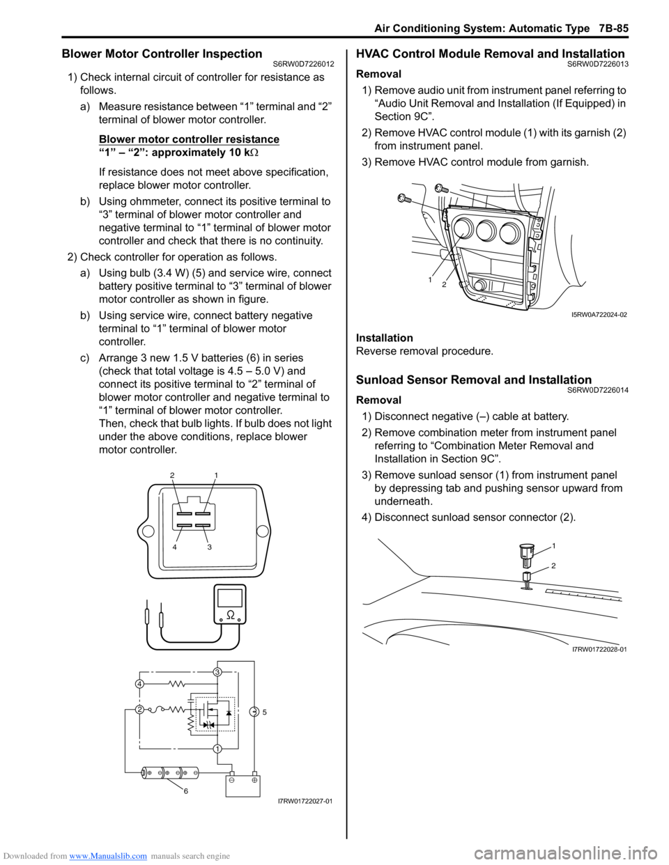
1) Check internal circuit of controller for resistance as
follows.
a) Measure resistance between “1” terminal and “2”
terminal of blower motor controller.
Blower motor controller resistance
“1” – “2”: approximately 10 kΩ
If resistance does not meet above specification,
replace blower motor controller.
b) Using ohmmeter, connect its positive terminal to
“3” terminal of blower motor controller and
negative terminal to “1” terminal of blower motor
controller and check that there is no continuity.
2) Check controller for operation as follows.
a) Using bulb (3.4 W) (5) and service wire, connect
battery positive terminal to “3” terminal of blower
motor controller as shown in figure.
b) Using service wire, connect battery negative
terminal to “1” terminal of blower motor
controller.
c) Arrange 3 new 1.5 V batteries (6) in series
(check that total voltage is 4.5 – 5.0 V) and
connect its positive terminal to “2” terminal of
blower motor controller and negative terminal to
“1” terminal of blower motor controller.
Then, check that bulb lights. If bulb does not light
under the above conditions, replace blower
motor controller.
HVAC Control Module Removal and InstallationS6RW0D7226013
Removal
1) Remove audio unit from instrument panel referring to
“Audio Unit Removal and Installation (If Equipped) in
Section 9C”.
2) Remove HVAC control module (1) with its garnish (2)
from instrument panel.
3) Remove HVAC control module from garnish.
Installation
Reverse removal procedure.
Sunload Sensor Removal and InstallationS6RW0D7226014
Removal
1) Disconnect negative (–) cable at battery.
2) Remove combination meter from instrument panel
referring to “Combination Meter Removal and
Installation in Section 9C”.
3) Remove sunload sensor (1) from instrument panel
by depressing tab and pushing sensor upward from
underneath.
4) Disconnect sunload sensor connector (2).
21
43
3
1 2 4
5
6I7RW01722027-01
12
I5RW0A722024-02
1
2
I7RW01722028-01
Page 1043 of 1556

Downloaded from www.Manualslib.com manuals search engine Air Bag System: 8B-4
• Never attempt to disassemble the seat belt
pretensioners (retractor assembly).
• If any abnormality is found, be sure to replace it with
new one as an assembly.
• When an abnormality is noted as existing in the live
(inactivated) seat belt pretensioner, be sure to activate
it before discarding it.
• When grease, cleaning agent oil, water, etc., got on
the seat belt pretensioners (retractor assembly), wipe
it off immediately with a dry cloth.
• If seat belt pretensioner was dropped from a height of
30 cm (1 ft) or more, it should be replaced with a new
one as an assembly.
WARNING!
• For handling and storage of a live seat belt
pretensioner, select a place where the
ambient temperature below 65 °C (150 °F),
without high humidity and away from
electric noise.
• Never carry the seat belt pretensioner by
webbing.
• When placing a live seat belt pretensioner
on the workbench or other surface, be sure
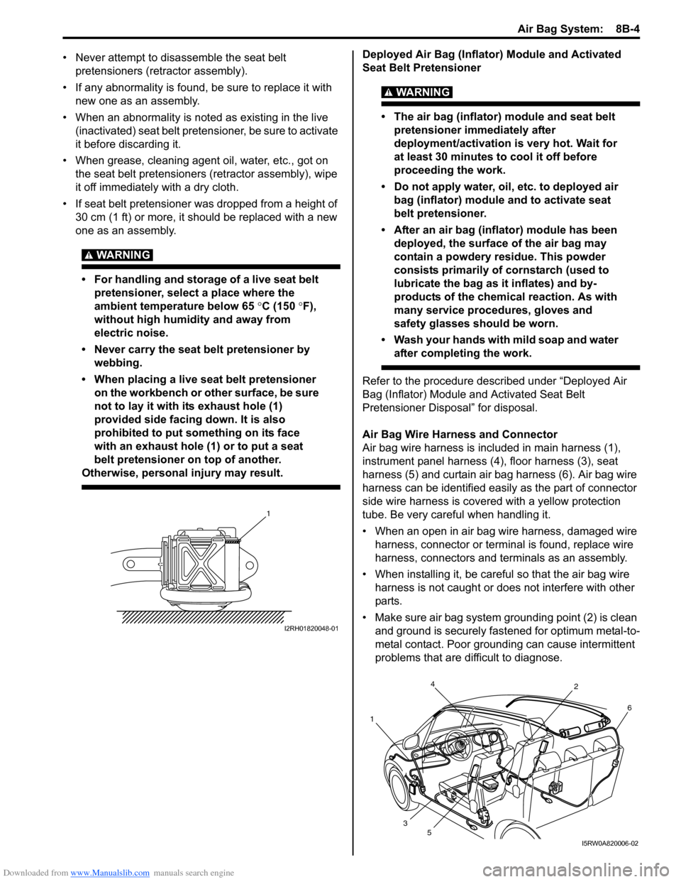
not to lay it with its exhaust hole (1)
provided side facing down. It is also
prohibited to put something on its face
with an exhaust hole (1) or to put a seat
belt pretensioner on top of another.
Otherwise, personal injury may result.
Deployed Air Bag (Inflator) Module and Activated
Seat Belt Pretensioner
WARNING!
• The air bag (inflator) module and seat belt
pretensioner immediately after
deployment/activation is very hot. Wait for
at least 30 minutes to cool it off before
proceeding the work.
• Do not apply water, oil, etc. to deployed air
bag (inflator) module and to activate seat
belt pretensioner.
• After an air bag (inflator) module has been
deployed, the surface of the air bag may
contain a powdery residue. This powder
consists primarily of cornstarch (used to
lubricate the bag as it inflates) and by-
products of the chemical reaction. As with
many service procedures, gloves and
safety glasses should be worn.
• Wash your hands with mild soap and water
after completing the work.
Refer to the procedure described under “Deployed Air
Bag (Inflator) Module and Activated Seat Belt
Pretensioner Disposal” for disposal.
Air Bag Wire Harness and Connector
Air bag wire harness is included in main harness (1),
instrument panel harness (4), floor harness (3), seat
harness (5) and curtain air bag harness (6). Air bag wire
harness can be identified easily as the part of connector
side wire harness is covered with a yellow protection
tube. Be very careful when handling it.
• When an open in air bag wire harness, damaged wire
harness, connector or terminal is found, replace wire
harness, connectors and terminals as an assembly.
• When installing it, be careful so that the air bag wire
harness is not caught or does not interfere with other
parts.
• Make sure air bag system grounding point (2) is clean
and ground is securely fastened for optimum metal-to-
metal contact. Poor grounding can cause intermittent
problems that are difficult to diagnose.
1
I2RH01820048-01
4
12
6
3
5
I5RW0A820006-02
Page 1129 of 1556

Downloaded from www.Manualslib.com manuals search engine Air Bag System: 8B-90
• Improperly formed or damaged terminals.
Check each connector terminal in problem circuits
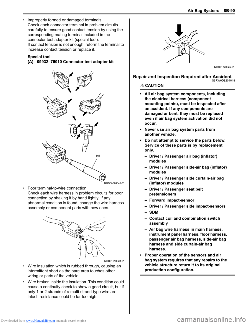
carefully to ensure good contact tension by using the
corresponding mating terminal included in the
connector test adapter kit (special tool).
If contact tension is not enough, reform the terminal to
increase contact tension or replace it.
Special tool
(A): 09932–76010 Connector test adapter kit
• Poor terminal-to-wire connection.
Check each wire harness in problem circuits for poor
connection by shaking it by hand lightly. If any
abnormal condition is found, change the wire harness
assembly or component parts with new ones.
• Wire insulation which is rubbed through, causing an
intermittent short as the bare area touches other
wiring or parts of the vehicle.
• Wire broken inside the insulation. This condition could
cause a continuity check to show a good circuit, but if
only 1 or 2 strands of a multi-strand-type wire are
intact, resistance could be far too high.
Repair and Inspection Required after AccidentS6RW0D8204048
CAUTION!
• All air bag system components, including
the electrical harness (component
mounting points), must be inspected after
an accident. If any components are
damaged or bent, they must be replaced
even if air bag system activation did not
occur.
• Never use air bag system parts from
another vehicle.
• Do not attempt to service the parts below.
Service of these parts is by replacement
only.
– Driver / Passenger air bag (inflator)
modules
– Driver / Passenger side-air bag (inflator)
modules
– Driver / Passenger side curtain-air bag
(inflator) modules
– Driver / Passenger seat belt
pretensioners
– Forward impact-sensor
– Driver / Passenger side impact-sensors
–SDM
– Contact coil and combination switch
assembly
– Air bag wire harness in main harness,
instrument panel harness, floor harness,
passenger air bag harness, side-air bag
harness and side curtain-air bag
harness.
• Proper operation of the sensors and air
bag system requires that any repairs to the
vehicle structure return it to its original
production configuration.
(A)
I4RS0A820045-01
IYSQ01010028-01
IYSQ01820025-01
Page 1136 of 1556

Downloaded from www.Manualslib.com manuals search engine 8B-97 Air Bag System:
Driver Air Bag (Inflator) Module InspectionS6RW0D8206006
WARNING!
Never disassemble air bag (inflator) module
or measure its resistance. Otherwise,
personal injury may result.
CAUTION!
If air bag (inflator) module was dropped from
a height of 90 cm (3 ft) or more, it should be
replaced.
Check air bag (inflator) module visually and if any of the
following is found, replace it with a new one.
• Air bag being deployed
• Trim cover (pad surface) (1) being cracked
• Inflator case (2) being damaged or having been
exposed to strong impact (dropped)
• Bend or deformity of air bag (inflator) module bracket.
Passenger Air Bag (Inflator) Module Removal
and Installation
S6RW0D8206007
WARNING!
• Never attempt to disassemble or repair the
passenger air bag (inflator) module. If any
abnormality is found, be sure to replace it
with new one as an assembly.
• Be sure to read “Precautions on Service
and Diagnosis of Air Bag System”,
“Precautions on Handling and Storage of
Air Bag System Components” and
“Precautions on Disposal of Air Bag and
Seat Belt Pretensioner” before starting to
work and observe every precaution during
work. Neglecting them may result in
personal injury or undeployment of the air
bag when necessary.
Removal
1) Disable air bag system. Refer to “Disabling Air Bag
System”.
2) Remove center ventilation louver with garnish
referring to “Center Ventilation Louver Removal and
Installation in Section 7A”.
3) Pull out glove box while pushing its stopper from
both right and left sides.
4) Remove passenger air bag (inflator) module
attaching bolts (1) and its facing cover bolt (6).
5) Hold up passenger air bag (inflator) module with its
facing cover (5) without extending wire harness (2)
to avoid air bag connector damage and to
disconnect passenger air bag (inflator) module
connector (3) as shown in figure.
a) Unlock lock button (4).
b) With lock button unlocked, disconnect connector.
6) Remove passenger air bag (inflator) module with its
facing cover (5) from instrument panel.
1
2
I5RW0A820067-01
“A”
5
“A”“A”
3
4a)
b)
2
6
1 1
I7RW01821033-01
Page 1138 of 1556

Downloaded from www.Manualslib.com manuals search engine 8B-99 Air Bag System:
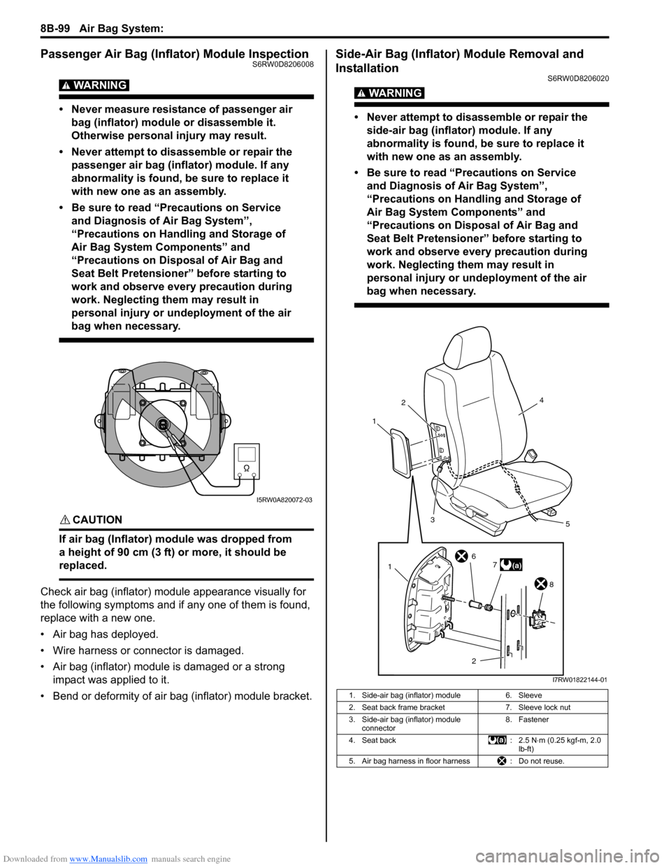
Passenger Air Bag (Inflator) Module InspectionS6RW0D8206008
WARNING!
• Never measure resistance of passenger air
bag (inflator) module or disassemble it.
Otherwise personal injury may result.
• Never attempt to disassemble or repair the
passenger air bag (inflator) module. If any
abnormality is found, be sure to replace it
with new one as an assembly.
• Be sure to read “Precautions on Service
and Diagnosis of Air Bag System”,
“Precautions on Handling and Storage of
Air Bag System Components” and
“Precautions on Disposal of Air Bag and
Seat Belt Pretensioner” before starting to
work and observe every precaution during
work. Neglecting them may result in
personal injury or undeployment of the air
bag when necessary.
CAUTION!
If air bag (Inflator) module was dropped from
a height of 90 cm (3 ft) or more, it should be
replaced.
Check air bag (inflator) module appearance visually for
the following symptoms and if any one of them is found,
replace with a new one.
• Air bag has deployed.
• Wire harness or connector is damaged.
• Air bag (inflator) module is damaged or a strong
impact was applied to it.
• Bend or deformity of air bag (inflator) module bracket.
Side-Air Bag (Inflator) Module Removal and
Installation
S6RW0D8206020
WARNING!
• Never attempt to disassemble or repair the
side-air bag (inflator) module. If any
abnormality is found, be sure to replace it
with new one as an assembly.
• Be sure to read “Precautions on Service
and Diagnosis of Air Bag System”,
“Precautions on Handling and Storage of
Air Bag System Components” and
“Precautions on Disposal of Air Bag and
Seat Belt Pretensioner” before starting to
work and observe every precaution during
work. Neglecting them may result in
personal injury or undeployment of the air
bag when necessary.
I5RW0A820072-03
1. Side-air bag (inflator) module 6. Sleeve
2. Seat back frame bracket 7. Sleeve lock nut
3. Side-air bag (inflator) module
connector8. Fastener
4. Seat back : 2.5 N⋅m (0.25 kgf-m, 2.0
lb-ft)
5. Air bag harness in floor harness : Do not reuse.
12
3
4
5
(a)7 6
8
2
1
I7RW01822144-01