2006 SUZUKI SX4 engine mount
[x] Cancel search: engine mountPage 1153 of 1556
Downloaded from www.Manualslib.com manuals search engine Air Bag System: 8B-114
21) Wash your hands with mild soap and water
afterward.
NOTE
Remaining steps are to be followed in the
unlikely event that air bag (inflator) module
did not deploy or seat belt pretensioner did
not activate.
22) Ensure that deployment harness has been
disconnected from 12 volts vehicle battery and that
its two banana plugs have been shorted together by
fully seating one banana plug into the other.
23) Disconnect deployment harness and adapter cable
from air bag (inflator) module or seat belt
pretensioner.
24) Temporarily store undeployed air bag (inflator)
module referring to “Precautions on Service and
Diagnosis of Air Bag System” for details.
25) Contact your local distributor for further assistance.
Deployment / Activation Inside of Vehicle
When the vehicle will be destroyed, or salvaged for
component parts, deploy the air bag modules and/or
activate seat belt pretensioners installed on vehicle.
NOTE
If equipped with the seat belt pretensioners,
activate both side of seat belt pretensioners
at the same time when using special tool (C).
1) Turn ignition switch to LOCK position, remove key
and put on safety glasses.
2) Remove all loose objects from front seats and
instrument panel.
3) Disconnect air bag (inflator) module or seat belt
pretensioner connector as follows.
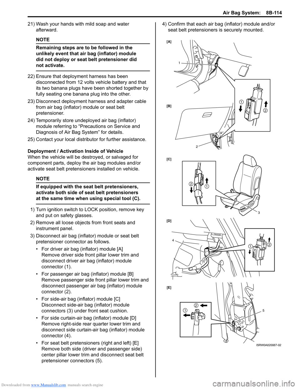
• For driver air bag (inflator) module [A]
Remove driver side front pillar lower trim and
disconnect driver air bag (inflator) module
connector (1).
• For passenger air bag (inflator) module [B]
Remove passenger side front pillar lower trim and
disconnect passenger air bag (inflator) module
connector (2).
• For side-air bag (inflator) module [C]
Disconnect side-air bag (inflator) module
connectors (3) under front seat cushion.
• For side curtain-air bag (inflator) module [D]
Remove right-side rear quarter lower trim and
disconnect side curtain-air bag (inflator) module
connector (4).
• For seat belt pretensioners (right and left) [E]
Remove both side (driver and passenger side)
center pillar lower trim and disconnect seat belt
pretensioner connectors (5).4) Confirm that each air bag (inflator) module and/or
seat belt pretensioners is securely mounted.
1
3
4
2
1
21
2
21
2
15 [A]
[B]
[C]
[D]
[E]
I5RW0A820087-02
Page 1157 of 1556
Downloaded from www.Manualslib.com manuals search engine Air Bag System: 8B-118
Specifications
Tightening Torque SpecificationsS6RW0D8207001
NOTE
The specified tightening torque is also described in the following.
“Side-Air Bag (Inflator) Module Removal and Installation”
Reference:
For the tightening torque of fastener not specified in this section, refer to “Fasteners Information in Section 0A”.
Special Tools and Equipment
Use of Special ToolsS6RW0D8208001
WARNING!
To avoid deployment when troubleshooting
the air bag system, do not use electrical
equipment such as a battery powered or AC
powered voltmeter, ohmmeter, etc., or any
type of electrical equipment other than that
specified. Do not use a non-powered probe
type tester.
Instructions must be followed carefully,
otherwise personal injury may result.
You should be familiar with the tools listed under the
heading “Special Tool”. You should be able to measure
voltage and resistance. You should be familiar with
proper use of a scan tool such as Air Bag Driver /
Passenger Load Tool, Connector Test Adapter Kit and
the Digital Multimeter.
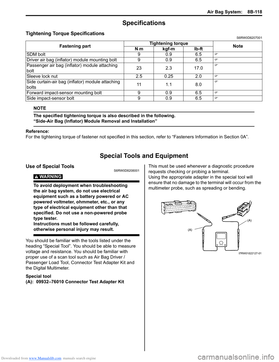
Special tool
(A): 09932–76010 Connector Test Adapter KitThis must be used whenever a diagnostic procedure
requests checking or probing a terminal.
Using the appropriate adapter in the special tool will
ensure that no damage to the terminal will occur from the
multimeter probe, such as spreading or bending. Fastening partTightening torque
Note
N⋅mkgf-mlb-ft
SDM bolt 9 0.9 6.5�)
Driver air bag (inflator) module mounting bolt 9 0.9 6.5�)
Passenger air bag (inflator) module attaching
bolt23 2.3 17.0�)
Sleeve lock nut 2.5 0.25 2.0�)
Side curtain-air bag (inflator) module attaching
bolts11 1.1 8.0�)
Forward impact-sensor mounting bolt 9 0.9 6.5�)
Side impact-sensor bolt 9 0.9 6.5�)
I7RW01822127-01
Page 1196 of 1556
Downloaded from www.Manualslib.com manuals search engine 9A-29 Wiring Systems:
L: Coupling harness
L: Floor antenna wire
Q: Side curtain air-bag wire
Q: Side air-bag (R) harness
Q: Side air-bag (L) harness
R: Fuel pump wireL164/N Rear door switch (L) L381/N Rear door wire (To J217)
L167/BLK Parking brake switch L382/N Rear door wire (To J218)
L170/N Seat belt switch L383/N Roof wire (To K152)
L174/N (IF
EQPD)2WD/4WD switchL384/YEL
(8ch)Side air-bag (R) harness (To Q133)
L283/BLK Pretensioner (Driver side)L385/YEL
(8ch)Side air-bag (L) harness (To Q134)
L285/BLK Pretensioner (Passenger side) L389/GRY Fuel pump wire (To R151)
L292/GRY (IF
EQPD)Back antenna L390/N Rear end door harness (To O231)
L293/BRN (IF
EQPD)Luggage antennaL391/N (IF
EQPD)Rear end door harness (To O232)
L294/BRN (IF
EQPD)Inside antenna L393/N High mounted stop light wire (To O233)
L296/N Rear ACC socketL395/YEL
(8ch)Side curtain air-bag wire (To Q132)
L301/BLK Diode #2L397/GRY (IF
EQPD)Coupling harness (To L408)
L312/N J/B No./Color Connective position No./Color Connective position
No./Color Connective position No./Color Connective position
L40/BLK (IF
EQPD)Coupling air temperature sensorL408/GRY
(IF EQPD)Floor harness (To L397)
L102/GRY
(IF EQPD)Coupling solenoid
No./Color Connective position No./Color Connective position
L307/BLK
(IF EQPD)TV antenna #1L409/GRY
(IF EQPD)Instrument panel antenna wire (To G355)
L308/BLK
(IF EQPD)TV antenna #2L410/GRY
(IF EQPD)Back door antenna wire (To O240)
No./Color Connective position No./Color Connective position
Q102/BLK
(8ch)Side curtain air-bag (R)Q132/YEL
(8ch)Floor harness (To L395)
Q103/BLK
(8ch)Side curtain air-bag (L)
No./Color Connective position No./Color Connective position
Q104/BLK
(8ch)Side air-bag inflator (R)Q133/YEL
(8ch)Floor harness (To L384)
No./Color Connective position No./Color Connective position
Q105/BLK
(8ch)Side air-bag inflator (L)Q134/YEL
(8ch)Floor harness (To L385)
No./Color Connective position No./Color Connective position
R101/BLK Fuel pump and gauge R151/GRY Floor harness (To L389)
Page 1198 of 1556
Downloaded from www.Manualslib.com manuals search engine 9A-31 Wiring Systems:
L: Floor antenna wire
Q: Side curtain air-bag wire
Q: Side air-bag (R) harness
Q: Side air-bag (L) harness
R: Fuel pump wireL170/N Seat belt switch L381/N Rear door wire (To J217)
L171/YEL (IF
EQPD)Seat heater switch (Driver side) L382/N Rear door wire (To J218)
L172/GRN (IF
EQPD)Seat heater switch (Passenger side) L383/N Roof wire (To K152)
L281/N (IF
EQPD)Seat heater (Driver side)L384/YEL
(8ch)Side air-bag (R) harness (To Q133)
L282/N (IF
EQPD)Seat heater (Passenger side)L385/YEL
(8ch)Side air-bag (L) harness (To Q134)
L283/BLK Pretensioner (Driver side) L389/GRY Fuel pump wire (To R151)
L285/BLK Pretensioner (Passenger side) L390/N Rear end door harness (To O231)
L292/GRY (IF
EQPD)Back antennaL391/N (IF
EQPD)Rear end door harness (To O232)
L293/BRN (IF
EQPD)Luggage antenna L393/N High mounted stop light wire (To O233)
L294/BRN (IF
EQPD)Inside antennaL395/YEL
(8ch)Side curtain air-bag wire (To Q132)
L296/N Rear ACC socketL399/YEL
(Taiwan)Instrument panel harness (To G349)
L301/BLK Diode #2L402/YEL
(Taiwan)Instrument panel harness (To G352) No./Color Connective position No./Color Connective position
No./Color Connective position No./Color Connective position
L307/BLK
(IF EQPD)TV antenna #1L409/GRY
(IF EQPD)Instrument panel antenna wire (To G355)
L308/BLK
(IF EQPD)TV antenna #2L410/GRY
(IF EQPD)Back door antenna wire (To O240)
No./Color Connective position No./Color Connective position
Q102/BLK
(8ch)Side curtain air-bag (R)Q132/YEL
(8ch)Floor harness (To L395)
Q103/BLK
(8ch)Side curtain air-bag (L)
No./Color Connective position No./Color Connective position
Q104/BLK
(8ch)Side air-bag inflator (R)Q133/YEL
(8ch)Floor harness (To L384)
No./Color Connective position No./Color Connective position
Q105/BLK
(8ch)Side air-bag inflator (L)Q134/YEL
(8ch)Floor harness (To L385)
No./Color Connective position No./Color Connective position
R101/BLK Fuel pump and gauge R151/GRY Floor harness (To L389)
Page 1199 of 1556
Downloaded from www.Manualslib.com manuals search engine Wiring Systems: 9A-32
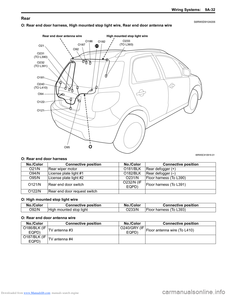
RearS6RW0D910A006
O: Rear end door harness, High mounted stop light wire, Rear end door antenna wire
O: Rear end door harness
O: High mounted stop light wire
O: Rear end door antenna wire
23
O231
(TO L390)
O232
(TO L391)
O181
O240
(TO L410)
O94
O122
O121
O95
O21
O92O187O186O182O233
(TO L393)
O
High mounted stop light wire Rear end door antenna wire
I6RW0C910916-01
No./Color Connective position No./Color Connective position
O21/N Rear wiper motor O181/BLK Rear defogger (+)
O94/N License plate light #1O182/BLK Rear defogger (–)
O95/N License plate light #2 O231/N Floor harness (To L390)
O121/N Rear end door switchO232/N (IF
EQPD)Floor harness (To L391)
O122/N Rear end door request switch
No./Color Connective position No./Color Connective position
O92/N High mounted stop light O233/N Floor harness (To L393)
No./Color Connective position No./Color Connective position
O186/BLK (IF
EQPD)TV antenna #3O240/GRY (IF
EQPD)Floor antenna wire (To L410)
O187/BLK (IF
EQPD)TV antenna #4
Page 1290 of 1556
Downloaded from www.Manualslib.com manuals search engine 9A-123 Wiring Systems:
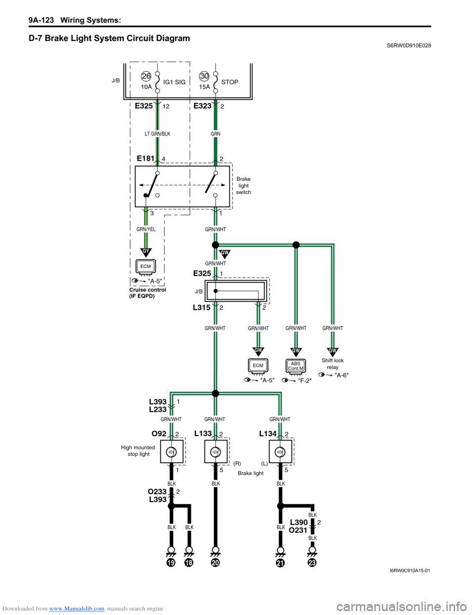
D-7 Brake Light System Circuit DiagramS6RW0D910E028
Brake
light
switch
Shift lock
relay
(R)
Brake light
GRNLT GRN/BLK
BLK
(L)
E181
L134
GRN/WHT
GRN/WHT
GRN/WHTGRN/WHT
5
L315
E325
J/B
"F-2"
ABS
Cont.M
GRN/WHT
2 2 1
"A-5"
ECM
21
GW
GW
GRN/YEL
"A-5"
ECM
GY
GW
42
31
J/B
L1332
52
1
GRN/WHT
"A-6"
GW
O92
High mounted
stop light
201918
BLKBLK
BLKBLKBLK
23
BLK
BLK
2
GRN/WHTGRN/WHTGRN/WHT
E3232
L393
L2331
O233
L3932
L390
O2312 15A
30STOP
E32512 10A
26IG1 SIG
Cruise control
(IF EQPD)
I6RW0C910A15-01
Page 1337 of 1556
Downloaded from www.Manualslib.com manuals search engine Lighting Systems: 9B-18
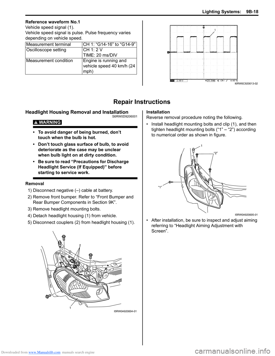
Reference waveform No.1
Vehicle speed signal (1).
Vehicle speed signal is pulse. Pulse frequency varies
depending on vehicle speed.
Repair Instructions
Headlight Housing Removal and InstallationS6RW0D9206001
WARNING!
• To avoid danger of being burned, don’t
touch when the bulb is hot.
• Don’t touch glass surface of bulb, to avoid
deteriorate as the case may be unclear
when bulb light on at dirty condition.
• Be sure to read “Precautions for Discharge
Headlight Service (If Equipped)” before
starting to service work.
Removal
1) Disconnect negative (–) cable at battery.
2) Remove front bumper. Refer to “Front Bumper and
Rear Bumper Components in Section 9K”.
3) Remove headlight mounting bolts.
4) Detach headlight housing (1) from vehicle.
5) Disconnect couplers (2) from headlight housing (1).Installation
Reverse removal procedure noting the following.
• Install headlight mounting bolts and clip (1), and then
tighten headlight mounting bolts (“1” – “2”) according
to numerical order as shown in figure.
• After installation, be sure to inspect and adjust aiming
referring to “Headlight Aiming Adjustment with
Screen”. Measurement terminal CH 1: “G14-16” to “G14-9”
Oscilloscope setting CH 1: 2 V
TIME: 20 ms/DIV
Measurement condition Engine is running and
vehicle speed 40 km/h (24
mph)
I6RW0C920013-02
2
1I5RW0A920004-01
1
“2”
“1”
I5RW0A920005-01
Page 1359 of 1556
Downloaded from www.Manualslib.com manuals search engine Instrumentation / Driver Info. / Horn: 9C-7
Low Fuel Warning Light Symptom DiagnosisS6RW0D9304005
NOTE
• Confirm that fuel meter is in good condition before referring to the following possible causes.
• When fuel level sensor circuit is open or short, fuel level meter indicates empty even if fuel tank
does not empty.
• The low fuel warning light comes ON when fuel level is lower than specification below.
Low fuel warning light operation:
Oil Pressure Warning Light Symptom DiagnosisS6RW0D9304006
Low fuel warning light operation: Fuel amount: Resistance of fuel level sensor:
ON (2WD) Approx. 7.5 liter Approx. 261 Ω
ON (4WD) Approx. 6.8 liter Approx. 261 Ω
Condition Possible cause Correction / Reference Item
Low fuel warning light
does not come ON when
fuel level is lower than
specificationCircuit fuse blownReplace fuse and check for short circuit.
Fuel level sensor faultyCheck fuel level sensor referring to “Fuel Level
Sensor Inspection”.
Wiring or grounding faultyRepair circuit.
Combination meter faultyReplace combination meter.
ECM faultyReplace after making sure that none of above
parts is faulty.
Low fuel warning light
comes ON steadyLow fuelRefill fuel.
Fuel level sensor faultyCheck fuel level sensor referring to “Fuel Level
Sensor Inspection”.
Wiring or grounding faultyRepair circuit.
Combination meter faultyReplace combination meter.
ECM faultyReplace after making sure that none of above
parts is faulty.
Condition Possible cause Correction / Reference Item
Oil pressure warning light
does not light up when
ignition switch is turned
to ON position at engine
offCircuit fuse blownReplace fuse and check for short circuit.
Oil pressure switch faultyCheck oil pressure switch referring to “Oil
Pressure Switch Inspection”.
Wiring or grounding faultyRepair circuit.
Combination meter faultyReplace combination meter.
BCM faultyReplace after making sure that none of above
parts is faulty.
Oil pressure warning light
stays ONOil pressure switch faultyCheck oil pressure switch referring to “Oil
Pressure Switch Inspection”.
Wiring or grounding faultyRepair circuit.
Combination meter faultyReplace combination meter.
BCM faultyReplace after making sure that none of above
parts is faulty.