2006 SUZUKI SX4 fuse
[x] Cancel search: fusePage 1408 of 1556
Downloaded from www.Manualslib.com manuals search engine 9E-23 Glass / Windows / Mirrors:
Pulse Sensor and Its Circuit Inspection
(Pinching Prevention Function Model)
S6RW0D9506029
NOTE
After replacing or disconnecting the driver
side power window regulator (motor), power
window main switch, battery and/or fuse,
make sure to execute the initial setting, (to
have the door glass closed position learned)
refer to “Power Window Main Switch
Initialization (Pinching Prevention Function
Model)”.
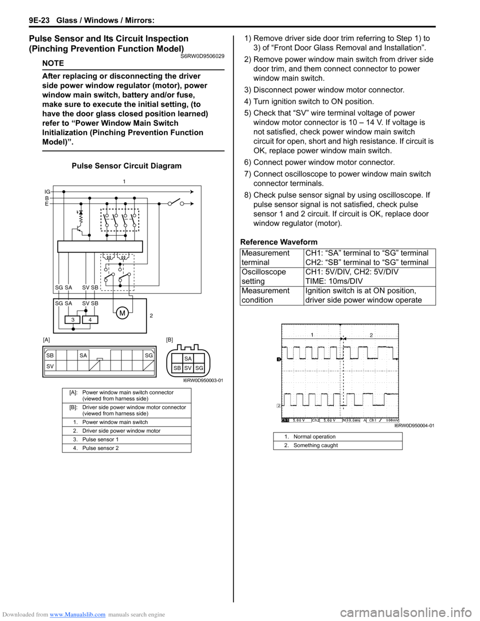
Pulse Sensor Circuit Diagram1) Remove driver side door trim referring to Step 1) to
3) of “Front Door Glass Removal and Installation”.
2) Remove power window main switch from driver side
door trim, and them connect connector to power
window main switch.
3) Disconnect power window motor connector.
4) Turn ignition switch to ON position.
5) Check that “SV” wire terminal voltage of power
window motor connector is 10 – 14 V. If voltage is
not satisfied, check power window main switch
circuit for open, short and high resistance. If circuit is
OK, replace power window main switch.
6) Connect power window motor connector.
7) Connect oscilloscope to power window main switch
connector terminals.
8) Check pulse sensor signal by using oscilloscope. If
pulse sensor signal is not satisfied, check pulse
sensor 1 and 2 circuit. If circuit is OK, replace door
window regulator (motor).
Reference Waveform
[A]: Power window main switch connector
(viewed from harness side)
[B]: Driver side power window motor connector
(viewed from harness side)
1. Power window main switch
2. Driver side power window motor
3. Pulse sensor 1
4. Pulse sensor 2
SG
SV SB SA
SG SV SBSA
B IG
E
4 3
SG SV SBSA
SG SV SBSA
2 1
[A] [B]
I6RW0D950003-01
Measurement
terminalCH1: “SA” terminal to “SG” terminal
CH2: “SB” terminal to “SG” terminal
Oscilloscope
settingCH1: 5V/DIV, CH2: 5V/DIV
TIME: 10ms/DIV
Measurement
conditionIgnition switch is at ON position,
driver side power window operate
1. Normal operation
2. Something caught
I6RW0D950004-01
Page 1409 of 1556
Downloaded from www.Manualslib.com manuals search engine Glass / Windows / Mirrors: 9E-24
Power Window Main Switch Initialization
(Pinching Prevention Function Model)
S6RW0D9506030
CAUTION!
• After replacing or disconnecting the driver
side door window regulator (motor), power
window main switch, battery or fuse, be
sure to execute initial setting (to have door
glass completely closed position learned).
If initial setting is not executed, correct
automatic operation (including pinching
prevention operation) would not be
available.
• Make sure that no foreign matter is
pinched while executing initial setting.
1) Open driver side door glass fully.
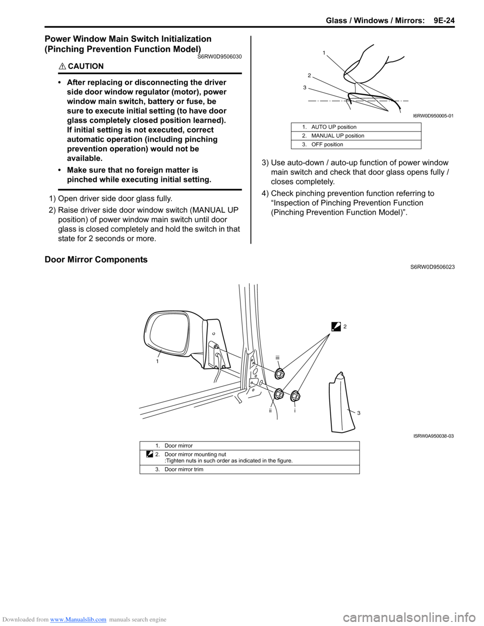
2) Raise driver side door window switch (MANUAL UP
position) of power window main switch until door
glass is closed completely and hold the switch in that
state for 2 seconds or more.3) Use auto-down / auto-up function of power window
main switch and check that door glass opens fully /
closes completely.
4) Check pinching prevention function referring to
“Inspection of Pinching Prevention Function
(Pinching Prevention Function Model)”.
Door Mirror ComponentsS6RW0D9506023 1. AUTO UP position
2. MANUAL UP position
3. OFF position
1
2
3
I6RW0D950005-01
2
1
i
iiiii
3
I5RW0A950038-03
1. Door mirror
2. Door mirror mounting nut
:Tighten nuts in such order as indicated in the figure.
3. Door mirror trim
Page 1414 of 1556
Downloaded from www.Manualslib.com manuals search engine 9F-3 Security and Locks:
Diagnostic Information and Procedures
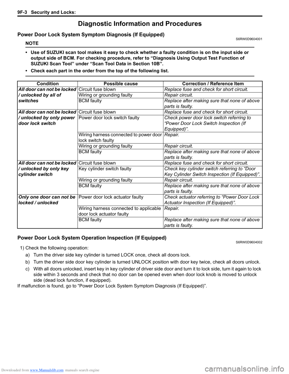
Power Door Lock System Symptom Diagnosis (If Equipped)S6RW0D9604001
NOTE
• Use of SUZUKI scan tool makes it easy to check whether a faulty condition is on the input side or
output side of BCM. For checking procedure, refer to “Diagnosis Using Output Test Function of
SUZUKI Scan Tool” under “Scan Tool Data in Section 10B”.
• Check each part in the order from the top of the following list.
Power Door Lock System Operation Inspection (If Equipped)S6RW0D9604002
1) Check the following operation:
a) Turn the driver side key cylinder is turned LOCK once, check all doors lock.
b) Turn the driver side door key cylinder is turned UNLOCK position with door key twice, check all doors unlock.
c) With all doors unlocked, insert key in key cylinder of driver side door and turn it to lock side, turn it again to lock
side within 3 seconds and check that no door can be opened even when door lock knob is moved to unlock
side (dead lock function, if equipped).
If malfunction is found, go to “Power Door Lock System Symptom Diagnosis (If Equipped)”. Condition Possible cause Correction / Reference Item
All door can not be locked
/ unlocked by all of
switchesCircuit fuse blownReplace fuse and check for short circuit.
Wiring or grounding faultyRepair circuit.
BCM faultyReplace after making sure that none of above
parts is faulty.
All door can not be locked
/ unlocked by only power
door lock switchCircuit fuse blownReplace fuse and check for short circuit.
Power door lock switch faultyCheck power door lock switch referring to
“Power Door Lock Switch Inspection (If
Equipped)”.
Wiring harness connected to power door
lock switch faultyRepair.
Wiring or grounding faultyRepair circuit.
BCM faultyReplace after making sure that none of above
parts is faulty.
All door can not be locked
/ unlocked by only key
cylinder switchCircuit fuse blownReplace fuse and check for short circuit.
Key cylinder switch faultyCheck key cylinder switch referring to “Door
Key Cylinder Switch Inspection (If Equipped)”.
Wiring or grounding faultyRepair circuit.
BCM faultyReplace after making sure that none of above
parts is faulty.
Only one door can not be
locked / unlockedPower door lock actuator faultyCheck actuator referring to “Power Door Lock
Actuator Inspection (If Equipped)”.
Wiring harness connected to applicable
door lock actuator faultyRepair.
BCM faultyReplace after making sure that none of above
parts is faulty.
Page 1416 of 1556
Downloaded from www.Manualslib.com manuals search engine 9F-5 Security and Locks:
Keyless Entry System Operation Inspection (If
Equipped)
S6RW0D9604004
NOTE
When performing the this inspection, make
sure to have any of the door once opened /
closed after the ignition key has been
removed from the ignition key cylinder.
1) Confirm that power door lock system operates
normally, refer to “Power Door Lock System
Operation Inspection (If Equipped)”.
2) All doors are closed and unlocked.
3) Check the following operation:
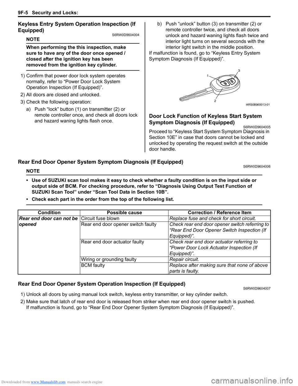
a) Push “lock” button (1) on transmitter (2) or
remote controller once, and check all doors lock
and hazard waning lights flash once.b) Push “unlock” button (3) on transmitter (2) or
remote controller twice, and check all doors
unlock and hazard waning lights flash twice and
interior light turns on several seconds with the
interior light switch in the middle position.
If malfunction is found, go to “Keyless Entry System
Symptom Diagnosis (If Equipped)”.
Door Lock Function of Keyless Start System
Symptom Diagnosis (If Equipped)
S6RW0D9604005
Proceed to “Keyless Start System Symptom Diagnosis in
Section 10E” in case that doors cannot be locked and
unlocked by operating the request switch at the outside
door handle.
Rear End Door Opener System Symptom Diagnosis (If Equipped)S6RW0D9604006
NOTE
• Use of SUZUKI scan tool makes it easy to check whether a faulty condition is on the input side or
output side of BCM. For checking procedure, refer to “Diagnosis Using Output Test Function of
SUZUKI Scan Tool” under “Scan Tool Data in Section 10B”.
• Check each part in the order from the top of the following list.
Rear End Door Opener System Operation Inspection (If Equipped)S6RW0D9604007
1) Unlock all doors by using manual lock switch, keyless entry transmitter, or key cylinder switch.
2) Make sure that latch of rear end door is released from striker when rear end door opener switch is pushed.
If malfunction is found, go to “Rear End Door Opener System Symptom Diagnosis (If Equipped)”.
1
3
2I4RS0B960013-01
Condition Possible cause Correction / Reference Item
Rear end door can not be
openedCircuit fuse blownReplace fuse and check for short circuit.
Rear end door opener switch faultyCheck rear end door opener switch referring to
“Rear End Door Opener Switch Inspection (If
Equipped)”.
Rear end door actuator faultyCheck rear end door actuator referring to
“Power Door Lock Actuator Inspection (If
Equipped)”.
Wiring or grounding faultyRepair circuit.
BCM faultyReplace after making sure that none of above
parts is faulty.
Page 1428 of 1556
Downloaded from www.Manualslib.com manuals search engine 9G-1 Seats:
Body, Cab and Accessories
Seats
Diagnostic Information and Procedures
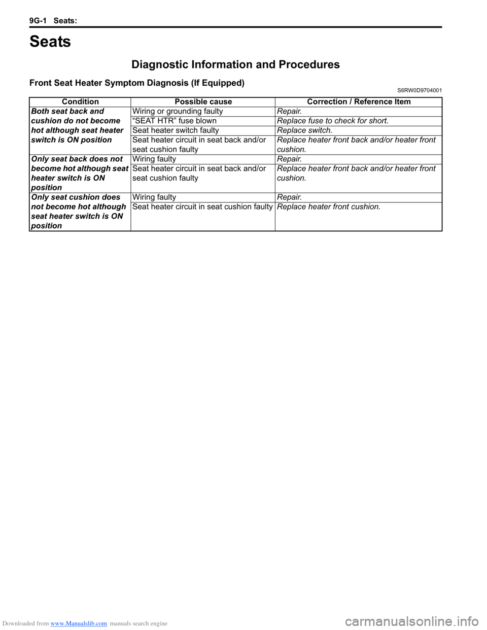
Front Seat Heater Symptom Diagnosis (If Equipped)S6RW0D9704001
Condition Possible cause Correction / Reference Item
Both seat back and
cushion do not become
hot although seat heater
switch is ON positionWiring or grounding faultyRepair.
“SEAT HTR” fuse blownReplace fuse to check for short.
Seat heater switch faultyReplace switch.
Seat heater circuit in seat back and/or
seat cushion faultyReplace heater front back and/or heater front
cushion.
Only seat back does not
become hot although seat
heater switch is ON
positionWiring faultyRepair.
Seat heater circuit in seat back and/or
seat cushion faultyReplace heater front back and/or heater front
cushion.
Only seat cushion does
not become hot although
seat heater switch is ON
positionWiring faultyRepair.
Seat heater circuit in seat cushion faultyReplace heater front cushion.
Page 1489 of 1556
Downloaded from www.Manualslib.com manuals search engine Body Electrical Control System: 10B-16
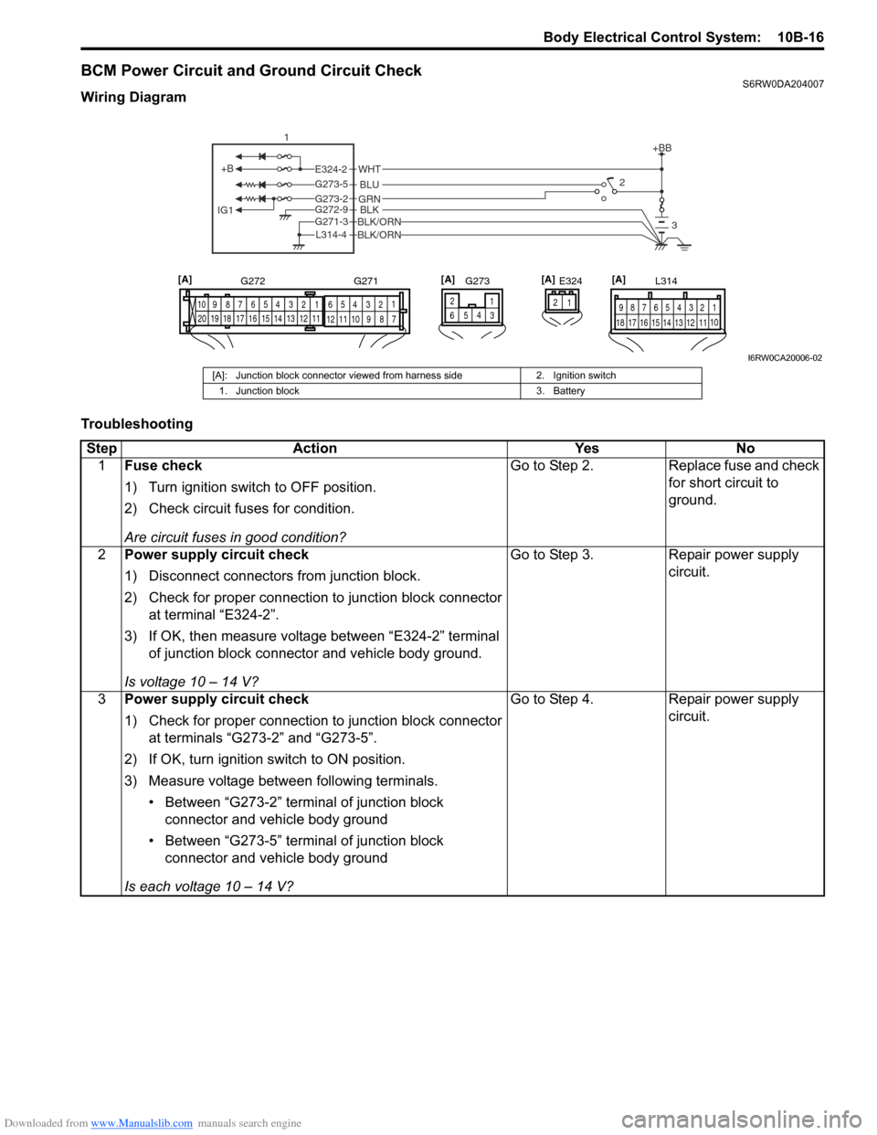
BCM Power Circuit and Ground Circuit CheckS6RW0DA204007
Wiring Diagram
Troubleshooting
+B
IG1
+BB
GRNG273-2BLKBLK/ORNG272-9
G271-3
BLK/ORNL314-4
BLU G273-5
WHTE324-22
3
1
E324 L314
1 2 4 53 6 7 8 9
10
11 12 13 14 15 16 17 181 21 2 4 53 61
2 4 53 6 7 8 9 10
7 8 9 10 11 12
11 12 13 14 15 16 17 18 19 20
G272 G271
1 2
4
65
G273[A] [A] [A]
3
[A]
I6RW0CA20006-02
[A]: Junction block connector viewed from harness side 2. Ignition switch
1. Junction block 3. Battery
Step Action Yes No
1Fuse check
1) Turn ignition switch to OFF position.
2) Check circuit fuses for condition.
Are circuit fuses in good condition?Go to Step 2. Replace fuse and check
for short circuit to
ground.
2Power supply circuit check
1) Disconnect connectors from junction block.
2) Check for proper connection to junction block connector
at terminal “E324-2”.
3) If OK, then measure voltage between “E324-2” terminal
of junction block connector and vehicle body ground.
Is voltage 10 – 14 V?Go to Step 3. Repair power supply
circuit.
3Power supply circuit check
1) Check for proper connection to junction block connector
at terminals “G273-2” and “G273-5”.
2) If OK, turn ignition switch to ON position.
3) Measure voltage between following terminals.
• Between “G273-2” terminal of junction block
connector and vehicle body ground
• Between “G273-5” terminal of junction block
connector and vehicle body ground
Is each voltage 10 – 14 V?Go to Step 4. Repair power supply
circuit.
Page 1503 of 1556
Downloaded from www.Manualslib.com manuals search engine Immobilizer Control System: 10C-1
Control Systems
Immobilizer Control System
Precautions
Precautions in Diagnosing TroublesS6RW0DA300001
• Before confirming the diagnostic trouble code (DTC),
do not disconnect connector from ECM, battery cable
from battery, ground wire harness, or main fuse. Such
disconnection will erase DTC stored in ECM.
• DTC stored in ECM memory can be checked as well
as cleared by using SUZUKI scan tool. Before using
SUZUKI scan tool, read its operator’s manual
carefully to know how to use it and what functions are
available.
• Be sure to read “Precautions for Electrical Circuit
Service in Section 00” before inspection.
• Communication of ECM, BCM, ABS control module,
TCM (if equipped), 4WD control module (if equipped),
keyless start control module (if equipped),
combination meter and DLC is established by CAN
(Controller Area Network). Therefore, handle CAN
communication lines with care referring to “Precaution
for CAN Communication System in Section 00”.
For CAN communication system, refer to description
on “CAN Communication System Description in
Section 1A”.
Precaution in Replacing ECMS6RW0DA300002
• If ECM is replaced with new or used one without
Immobilizer control function, the engine will not be
started. In case of the above, check if the newly
installed ECM has Immobilizer control function.
• After ECM is replaced with new one or used one, the
transponder code in the transponder built in the
ignition key has to be registered with ECM. Or, the
engine cannot be started up. For the registration
procedure, refer to “Procedure after ECM
Replacement”.
Precaution in Replacing Ignition KeyS6RW0DA300003
To register ignition key in case of replacing key(s) and/or
making spare key(s), the transponder code in the ignition
key is registered with ECM. Or the engine can not be
started up. For the registration procedure, refer to
“Registration of the Ignition Key”.
Precautions in Handling Immobilizer Control
System
S6RW0DA300004
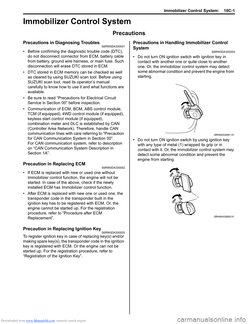
• Do not turn ON ignition switch with ignition key in
contact with another one or quite close to another
one. Or, the immobilizer control system may detect
some abnormal condition and prevent the engine from
starting.
• Do not turn ON ignition switch by using ignition key
with any type of metal (1) wrapped its grip or in
contact with it. Or, the immobilizer control system may
detect some abnormal condition and prevent the
engine from starting.
I3RH0AA30001-01
1
I3RH0AA30002-01
Page 1506 of 1556
Downloaded from www.Manualslib.com manuals search engine 10C-4 Immobilizer Control System:
BLK/WHT
BLK/ORN12V
G17-1
G17-2
12V
5V
12V
12VYEL/RED
YEL/BLK
G17-4
G17-3
5V
BRNBRN/YELBLK/YEL
1 2
22
2 34
251014
15
1 2 3
4 G17
[A]
5
6
G16-20 G16-29 G16-30 G146-3 G146-7 G146-8
WHT/RED
5V
5V
9
G16-18G16-19 E01-13
E01-28
BLU
RED
WHTE08-12
E08-1E01-18
E01-3
RED
WHTE08-13
E08-2
WHT
RED
G05-4
G05-2
12V
G05-35 8
11
G17-5WHT 76
G17-6WHT/RED
17
REDWHT
REDWHT
G241-10 G241-7
IG1
18
WHT
REDG05-1
G05-3
16 [C]
I6RW0DA30002-01
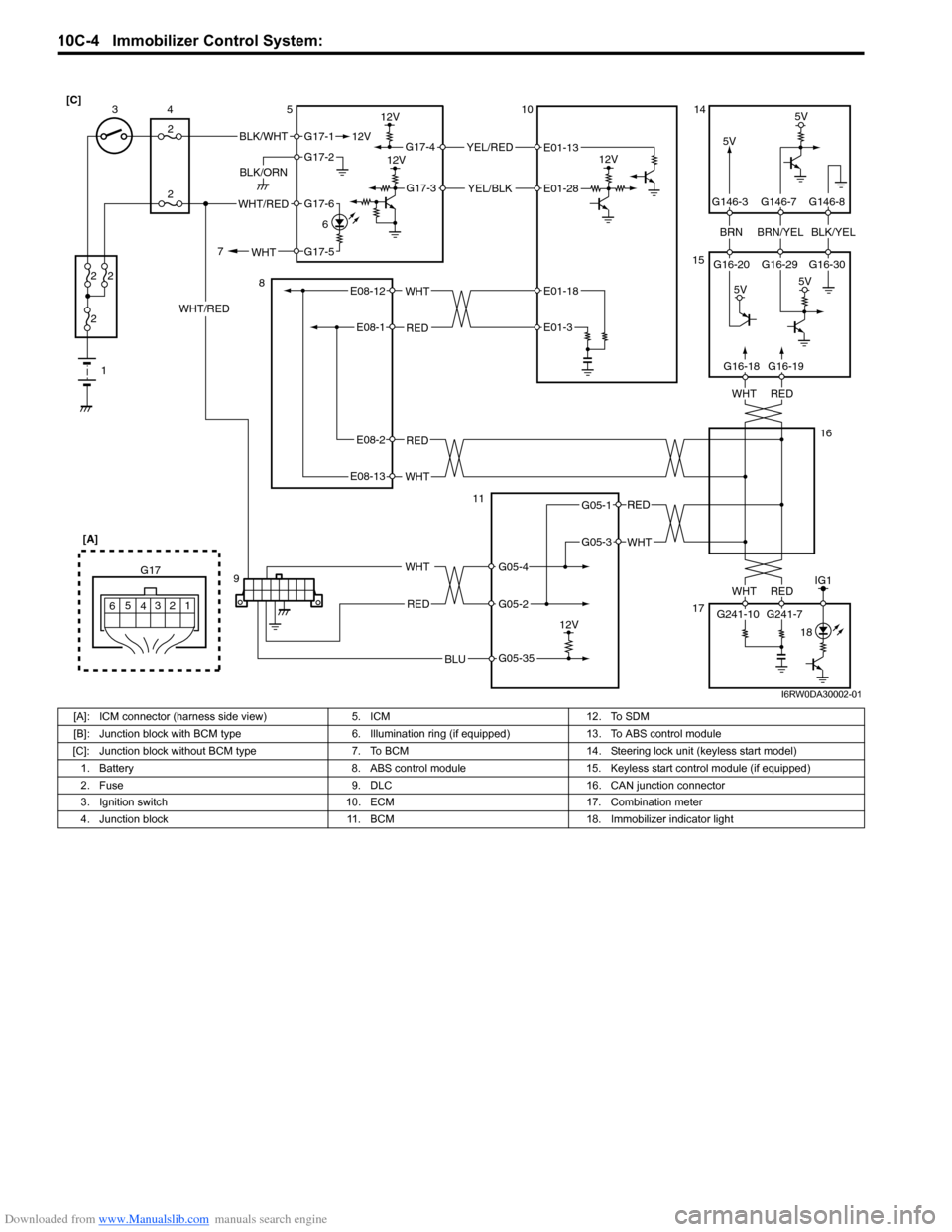
[A]: ICM connector (harness side view) 5. ICM 12. To SDM
[B]: Junction block with BCM type 6. Illumination ring (if equipped) 13. To ABS control module
[C]: Junction block without BCM type 7. To BCM 14. Steering lock unit (keyless start model)
1. Battery 8. ABS control module 15. Keyless start control module (if equipped)
2. Fuse 9. DLC 16. CAN junction connector
3. Ignition switch 10. ECM 17. Combination meter
4. Junction block 11. BCM 18. Immobilizer indicator light