2006 SUZUKI SX4 fuse
[x] Cancel search: fusePage 1364 of 1556
Downloaded from www.Manualslib.com manuals search engine 9C-12 Instrumentation / Driver Info. / Horn:
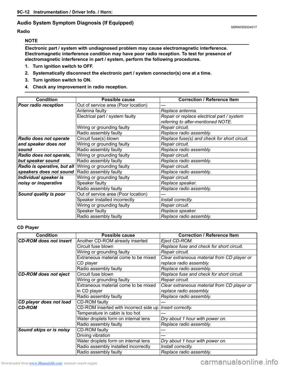
Audio System Symptom Diagnosis (If Equipped)S6RW0D9304017
Radio
NOTE
Electronic part / system with undiagnosed problem may cause electromagnetic interference.
Electromagnetic interference condition may have poor radio reception. To test for presence of
electromagnetic interference in part / system, perform the following procedures.
1. Turn ignition switch to OFF.
2. Systematically disconnect the electronic part / system connector(s) one at a time.
3. Turn ignition switch to ON.
4. Check any improvement in radio reception.
CD PlayerCondition Possible cause Correction / Reference Item
Poor radio receptionOut of service area (Poor location)—
Antenna faultyReplace antenna.
Electrical part / system faultyRepair or replace electrical part / system
referring to after-mentioned NOTE.
Wiring or grounding faultyRepair circuit.
Radio assembly faultyReplace radio assembly.
Radio does not operate
and speaker does not
soundCircuit fuse(s) blownReplace fuse(s) and check for short circuit.
Wiring or grounding faultyRepair circuit.
Radio assembly faultyReplace radio assembly.
Radio does not operate,
but speaker soundWiring or grounding faultyRepair circuit.
Radio assembly faultyReplace radio assembly.
Radio is operative, but all
speakers does not soundWiring or grounding faultyRepair circuit.
Radio assembly faultyReplace radio assembly.
Individual speaker is
noisy or inoperativeWiring or grounding faultyRepair circuit.
Speaker faultyReplace speaker.
Radio assembly faultyReplace radio assembly.
Sound quality is poorOut of service area (Poor location)—
Speaker installed incorrectlyInstall correctly.
Wiring or grounding faultyRepair circuit.
Speaker faultyReplace speaker.
Radio assembly faultyReplace radio assembly.
Condition Possible cause Correction / Reference Item
CD-ROM does not insertAnother CD-ROM already insertedEject CD-ROM.
Circuit fuse blownReplace fuse and check for short circuit.
Wiring or grounding faultyRepair circuit.
Extraneous material come to be mixed
CD playerClear extraneous material from CD player or
replace radio assembly.
Radio assembly faultyReplace radio assembly.
CD-ROM does not ejectCircuit fuse blownReplace fuse and check for short circuit.
Wiring or grounding faultyRepair circuit.
Extraneous material come to be mixed
in CD playerClear extraneous material from CD player or
replace radio assembly.
Radio assembly faultyReplace radio assembly.
CD player does not load
CD-ROMCD-ROM faulty—
CD-ROM inserted with incorrect side upInsert correctly.
Temperature in cabin is too hot—
Water droplets form on internal lensDry about 1 hour with power on.
Radio assembly faultyReplace radio assembly.
Sound skips or is noisyCD-ROM faulty—
Driving vibration—
Water droplets form on internal lensDry about 1 hour with power on.
Radio assembly installed incorrectlyInstall correctly.
Radio assembly faultyReplace radio assembly.
Page 1365 of 1556
Downloaded from www.Manualslib.com manuals search engine Instrumentation / Driver Info. / Horn: 9C-13
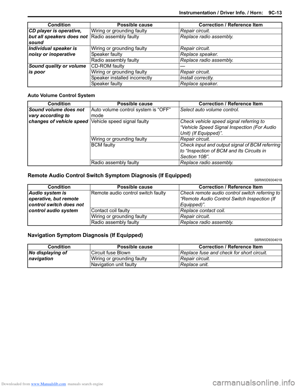
Auto Volume Control System
Remote Audio Control Switch Symptom Diagnosis (If Equipped)S6RW0D9304018
Navigation Symptom Diagnosis (If Equipped)S6RW0D9304019
CD player is operative,
but all speakers does not
soundWiring or grounding faultyRepair circuit.
Radio assembly faultyReplace radio assembly.
Individual speaker is
noisy or inoperativeWiring or grounding faultyRepair circuit.
Speaker faultyReplace speaker.
Radio assembly faultyReplace radio assembly.
Sound quality or volume
is poorCD-ROM faulty—
Wiring or grounding faultyRepair circuit.
Speaker installed incorrectlyInstall correctly.
Speaker faultyReplace speaker. Condition Possible cause Correction / Reference Item
Condition Possible cause Correction / Reference Item
Sound volume does not
vary according to
changes of vehicle speedAuto volume control system is “OFF”
modeSelect auto volume control.
Vehicle speed signal faultyCheck vehicle speed signal referring to
“Vehicle Speed Signal Inspection (For Audio
Unit) (If Equipped)”.
Wiring or grounding faultyRepair circuit.
BCM faultyCheck input and output signal of BCM referring
to “Inspection of BCM and Its Circuits in
Section 10B”.
Radio assembly faultyReplace radio assembly.
Condition Possible cause Correction / Reference Item
Audio system is
operative, but remote
control switch does not
control audio systemRemote audio control switch faultyCheck remote audio control switch referring to
“Remote Audio Control Switch Inspection (If
Equipped)”.
Contact coil faultyReplace contact coil.
Wiring or grounding faultyRepair circuit.
Radio assembly faultyReplace radio assembly.
Condition Possible cause Correction / Reference Item
No displaying of
navigationCircuit fuse BlownReplace fuse and check for short circuit.
Wiring or grounding faultyRepair circuit.
Navigation unit faultyReplace unit.
Page 1375 of 1556
Downloaded from www.Manualslib.com manuals search engine Wipers / Washers: 9D-1
Body, Cab and Accessories
Wipers / Washers
Diagnostic Information and Procedures
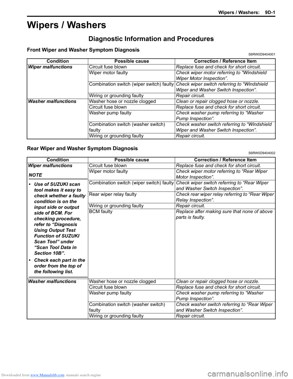
Front Wiper and Washer Symptom DiagnosisS6RW0D9404001
Rear Wiper and Washer Symptom DiagnosisS6RW0D9404002
Condition Possible cause Correction / Reference Item
Wiper malfunctionsCircuit fuse blownReplace fuse and check for short circuit.
Wiper motor faultyCheck wiper motor referring to “Windshield
Wiper Motor Inspection”.
Combination switch (wiper switch) faultyCheck wiper switch referring to “Windshield
Wiper and Washer Switch Inspection”.
Wiring or grounding faultyRepair circuit.
Washer malfunctionsWasher hose or nozzle cloggedClean or repair clogged hose or nozzle.
Circuit fuse blownReplace fuse and check for short circuit.
Washer pump faultyCheck washer pump referring to “Washer
Pump Inspection”.
Combination switch (washer switch)
faultyCheck washer switch referring to “Windshield
Wiper and Washer Switch Inspection”.
Wiring or grounding faultyRepair circuit.
Condition Possible cause Correction / Reference Item
Wiper malfunctions
NOTE
• Use of SUZUKI scan
tool makes it easy to
check whether a faulty
condition is on the
input side or output
side of BCM. For
checking procedure,
refer to “Diagnosis
Using Output Test
Function of SUZUKI
Scan Tool” under
“Scan Tool Data in
Section 10B”.
• Check each part in the
order from the top of
the following list.
Circuit fuse blownReplace fuse and check for short circuit.
Wiper motor faultyCheck wiper motor referring to “Rear Wiper
Motor Inspection”.
Combination switch (wiper switch) faultyCheck wiper switch referring to “Rear Wiper
and Washer Switch Inspection”.
Rear wiper relay faultyCheck rear wiper relay referring to “Rear Wiper
Relay Inspection”.
Wiring or grounding faultyRepair circuit.
BCM faultyReplace after making sure that none of above
parts is faulty.
Washer malfunctionsWasher hose or nozzle cloggedClean or repair clogged hose or nozzle.
Circuit fuse blownReplace fuse and check for short circuit.
Washer pump faultyCheck washer pump referring to “Washer
Pump Inspection”.
Combination switch (washer switch)
faultyCheck washer switch referring to “Rear Wiper
and Washer Switch Inspection”.
Wiring or grounding faultyRepair circuit.
Page 1386 of 1556
Downloaded from www.Manualslib.com manuals search engine 9E-1 Glass / Windows / Mirrors:
Body, Cab and Accessories
Glass / Windows / Mirrors
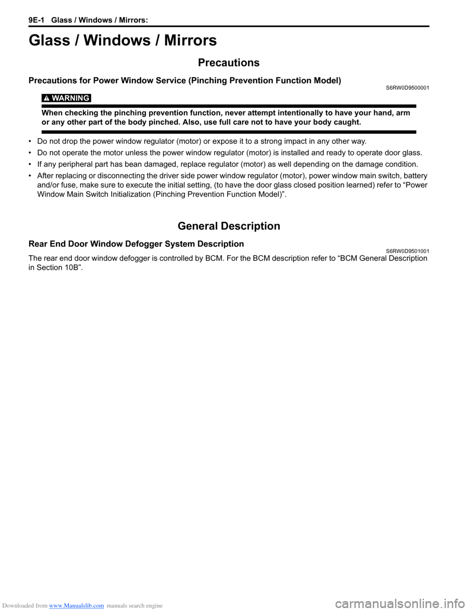
Precautions
Precautions for Power Window Service (Pinching Prevention Function Model)S6RW0D9500001
WARNING!
When checking the pinching prevention function, never attempt intentionally to have your hand, arm
or any other part of the body pinched. Also, use full care not to have your body caught.
• Do not drop the power window regulator (motor) or expose it to a strong impact in any other way.
• Do not operate the motor unless the power window regulator (motor) is installed and ready to operate door glass.
• If any peripheral part has bean damaged, replace regulator (motor) as well depending on the damage condition.
• After replacing or disconnecting the driver side power window regulator (motor), power window main switch, battery
and/or fuse, make sure to execute the initial setting, (to have the door glass closed position learned) refer to “Power
Window Main Switch Initialization (Pinching Prevention Function Model)”.
General Description
Rear End Door Window Defogger System DescriptionS6RW0D9501001
The rear end door window defogger is controlled by BCM. For the BCM description refer to “BCM General Description
in Section 10B”.
Page 1387 of 1556
Downloaded from www.Manualslib.com manuals search engine Glass / Windows / Mirrors: 9E-2
Schematic and Routing Diagram
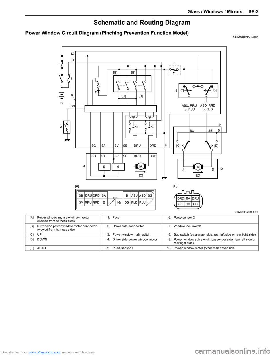
Power Window Circuit Diagram (Pinching Prevention Function Model)S6RW0D9502001
6 5
[C][D]
DSB IG
E
SG SV SBSA DRU DRD
SG SV SBSA DRU DRDASU, RRU
or RLUASD, RRD
or RLD
[C][C]
D U
[C][D]
SU SBB [C][D] [E] [E]
ESG
SV SB SADRU DRD B ASU ASD
RRU
RRDDS IG RLD RLUSG SV SBSA DRU DRD [A] [B] 1
1
3
2
47
8
9
10
I6RW0D950001-01
[A]: Power window main switch connector
(viewed from harness side)1. Fuse 6. Pulse sensor 2
[B]: Driver side power window motor connector
(viewed from harness side)2. Driver side door switch 7. Window lock switch
[C]: UP 3. Power window main switch 8. Sub switch (passenger side, rear left side or rear light side)
[D]: DOWN 4. Driver side power window motor 9. Power window sub switch (passenger side, rear left side or
rear light side)
[E]: AUTO 5. Pulse sensor 1 10. Power window motor (other than driver side)
Page 1388 of 1556
Downloaded from www.Manualslib.com manuals search engine 9E-3 Glass / Windows / Mirrors:
Diagnostic Information and Procedures
Rear End door Window Defogger Symptom DiagnosisS6RW0D9504001
NOTE
• Use of SUZUKI scan tool makes it easy to check whether a faulty condition is on the input side or
output side of BCM. For checking procedure, refer to “Diagnosis Using Output Test Function of
SUZUKI Scan Tool” under “Scan Tool Data in Section 10B”.
• Check each part in the order from the top of the following list.
Power Window Control System Symptom DiagnosisS6RW0D9504002
Condition Possible cause Correction / Reference Item
Rear end door window
defogger does not
operateCircuit fuse blownReplace fuse and check for short circuit.
Rear end door window defogger switch
faultyCheck rear end door window defogger switch
referring to “Rear End Door Window Defogger
Switch Inspection”.
Rear end door window defogger relay
faultyCheck rear end door window defogger relay
referring to “Rear End Door Window Defogger
Relay Inspection”.
Defogger wire faultyCheck defogger wire referring to “Rear End
Door Window Defogger Wire Inspection”.
Wiring or grounding faultyRepair circuit.
BCM faultyReplace after making sure that none of above
parts is faulty.
Condition Possible cause Correction / Reference Item
All power windows do not
operateCircuit fuse blownReplace fuse and check for short circuit.
Power window main switch faultyCheck power window main switch referring to
“Power Window Main Switch Inspection”.
Ignition switch faultyCheck ignition switch referring to “Ignition
Switch Inspection in Section 9C”.
Wiring or grounding faultyRepair circuit.
Only one power window
does not operatePower window main switch faultyCheck power window main switch referring to
“Power Window Main Switch Inspection”.
Power window sub switch faultyCheck power window sub switch referring to
“Power Window Sub Switch Inspection”.
Wiring and/or coupler faultyCheck wiring and/or coupler.
Power window regulator faultyCheck window regulator.
Power window motor faultyCheck power window motor.
Wiring or grounding faultyRepair circuit.
Driver side door glass
fails to perform auto-up /
auto-down function
(Pinching Prevention
Function Model)Power window main switch faultyCheck power window main switch referring to
“Power Window Main Switch Inspection”.
Power window motor faultyCheck power window motor referring to “Pulse
Sensor and Its Circuit Inspection (Pinching
Prevention Function Model)”.
Wiring or grounding faultyRepair circuit.
Driver side door glass
fails to lower back even
when a foreign matter is
pinched (Pinching
Prevention Function
Model)Power window main switch has not been
initializedExecute the initial setting of power window
main switch referring to “Power Window Main
Switch Initialization (Pinching Prevention
Function Model)”.
Power window main switch faultyCheck power window main switch referring to
“Power Window Main Switch Inspection”.
Power window motor faultyCheck power window motor referring to “Pulse
Sensor and Its Circuit Inspection (Pinching
Prevention Function Model)”.
Page 1389 of 1556
Downloaded from www.Manualslib.com manuals search engine Glass / Windows / Mirrors: 9E-4
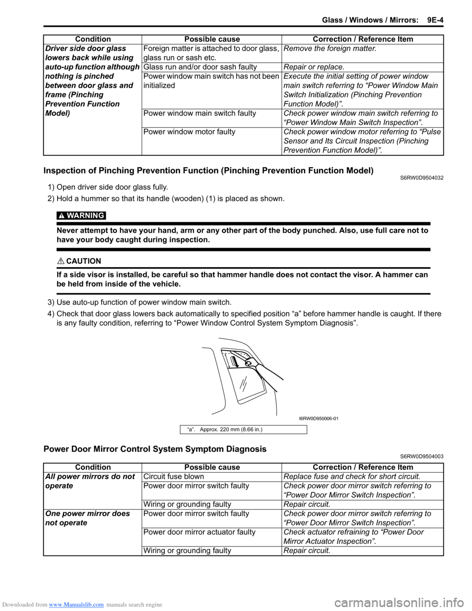
Inspection of Pinching Prevention Function (Pinching Prevention Function Model)S6RW0D9504032
1) Open driver side door glass fully.
2) Hold a hummer so that its handle (wooden) (1) is placed as shown.
WARNING!
Never attempt to have your hand, arm or any other part of the body punched. Also, use full care not to
have your body caught during inspection.
CAUTION!
If a side visor is installed, be careful so that hammer handle does not contact the visor. A hammer can
be held from inside of the vehicle.
3) Use auto-up function of power window main switch.
4) Check that door glass lowers back automatically to specified position “a” before hammer handle is caught. If there
is any faulty condition, referring to “Power Window Control System Symptom Diagnosis”.
Power Door Mirror Control System Symptom DiagnosisS6RW0D9504003
Driver side door glass
lowers back while using
auto-up function although
nothing is pinched
between door glass and
frame (Pinching
Prevention Function
Model)Foreign matter is attached to door glass,
glass run or sash etc.Remove the foreign matter.
Glass run and/or door sash faultyRepair or replace.
Power window main switch has not been
initializedExecute the initial setting of power window
main switch referring to “Power Window Main
Switch Initialization (Pinching Prevention
Function Model)”.
Power window main switch faultyCheck power window main switch referring to
“Power Window Main Switch Inspection”.
Power window motor faultyCheck power window motor referring to “Pulse
Sensor and Its Circuit Inspection (Pinching
Prevention Function Model)”. Condition Possible cause Correction / Reference Item
“a”. Approx. 220 mm (8.66 in.)
I6RW0D950006-01
Condition Possible cause Correction / Reference Item
All power mirrors do not
operateCircuit fuse blownReplace fuse and check for short circuit.
Power door mirror switch faultyCheck power door mirror switch referring to
“Power Door Mirror Switch Inspection”.
Wiring or grounding faultyRepair circuit.
One power mirror does
not operatePower door mirror switch faultyCheck power door mirror switch referring to
“Power Door Mirror Switch Inspection”.
Power door mirror actuator faultyCheck actuator refraining to “Power Door
Mirror Actuator Inspection”.
Wiring or grounding faultyRepair circuit.
Page 1390 of 1556
Downloaded from www.Manualslib.com manuals search engine 9E-5 Glass / Windows / Mirrors:
Door Mirror Heater Symptom Diagnosis (If Equipped)S6RW0D9504004
NOTE
• Use of SUZUKI scan tool makes it easy to check whether a faulty condition is on the input side or
output side of BCM. For checking procedure, refer to “Diagnosis Using Output Test Function of
SUZUKI Scan Tool” under “Scan Tool Data in Section 10B”.
• Check each part in the order from the top of the following list.
Repair Instructions
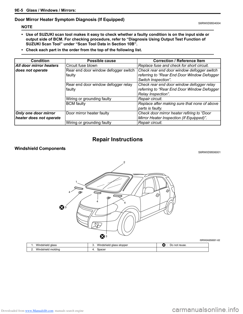
Windshield ComponentsS6RW0D9506001
Condition Possible cause Correction / Reference Item
All door mirror heaters
does not operateCircuit fuse blownReplace fuse and check for short circuit.
Rear end door window defogger switch
faultyCheck rear end door window defogger switch
referring to “Rear End Door Window Defogger
Switch Inspection”.
Rear end door window defogger relay
faultyCheck rear end door window defogger relay
referring to “Rear End Door Window Defogger
Relay Inspection”.
Wiring or grounding faultyRepair circuit.
BCM faultyReplace after making sure that none of above
parts is faulty.
Only one door mirror
heater does not operateDoor mirror heater faultyCheck door mirror heater refiring to “Door
Mirror Heater Inspection (If Equipped)”.
Wiring or grounding faultyRepair circuit.
3 31
2
44
4
I5RW0A950001-02
1. Windshield glass 3. Windshield glass stopper : Do not reuse.
2. Windshield molding 4. Spacer