2006 SUZUKI SX4 temperature sensor
[x] Cancel search: temperature sensorPage 1354 of 1556
Downloaded from www.Manualslib.com manuals search engine 9C-2 Instrumentation / Driver Info. / Horn:
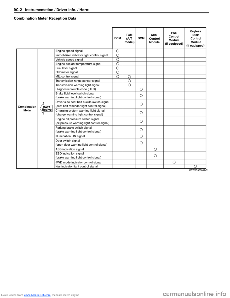
Combination Meter Reception Data
ECM BCM
Keyless
Start
Control
Module
(if equipped)
Combination
Meter4WD
Control
Module
(if equipped)TCM
(A/T
model)
Engine speed signal
Immobilizer indicator light control signal
Vehicle speed signal
Engine coolant temperature signal
Fuel level signal
MIL control signal
Transmission range sensor signal
Transmission warning light signal
Diagnostic trouble code (DTC)
Brake fluid level switch signal
(brake warning light control signal)
Driver side seat belt buckle switch signal
(seat belt reminder light control signal)
Charging system warning light signal
(charge warning light control signal)
Engine oil pressure switch signal
(oil pressure warning light control signal)
Parking brake switch signal
(brake warning light control signal)
Illumination ON signal
Door switch signal
(open door warning light control signal)
ABS indication signal
EBD indication signal
(brake warning light control signal)
4WD mode indicator control signal
Key indicator light control signal
ABS
Control
Module
Odometer signal
DATA
Recive
I6RW0D930001-01
Page 1358 of 1556
Downloaded from www.Manualslib.com manuals search engine 9C-6 Instrumentation / Driver Info. / Horn:
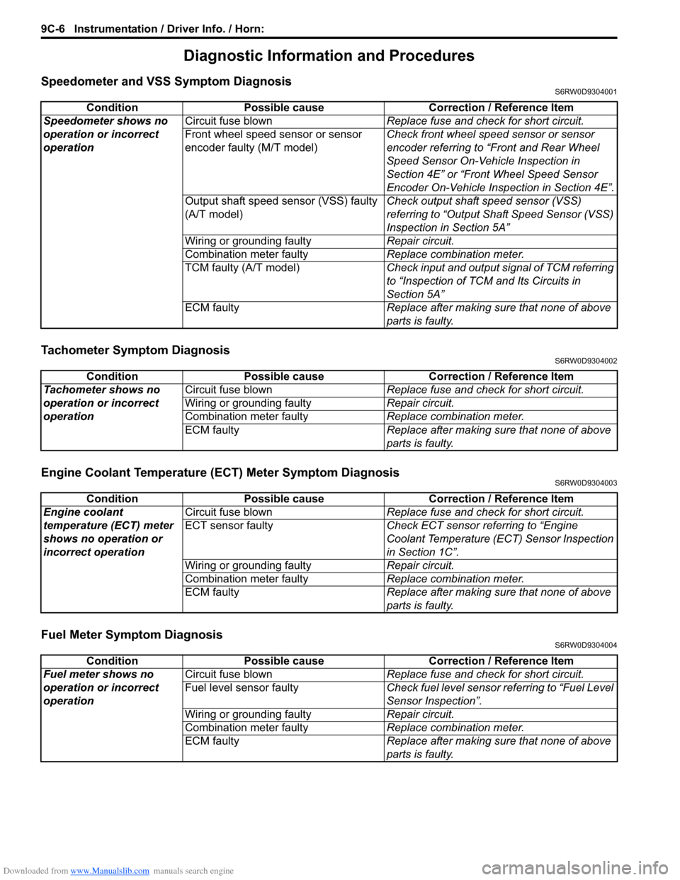
Diagnostic Information and Procedures
Speedometer and VSS Symptom DiagnosisS6RW0D9304001
Tachometer Symptom DiagnosisS6RW0D9304002
Engine Coolant Temperature (ECT) Meter Symptom DiagnosisS6RW0D9304003
Fuel Meter Symptom DiagnosisS6RW0D9304004
Condition Possible cause Correction / Reference Item
Speedometer shows no
operation or incorrect
operationCircuit fuse blownReplace fuse and check for short circuit.
Front wheel speed sensor or sensor
encoder faulty (M/T model)Check front wheel speed sensor or sensor
encoder referring to “Front and Rear Wheel
Speed Sensor On-Vehicle Inspection in
Section 4E” or “Front Wheel Speed Sensor
Encoder On-Vehicle Inspection in Section 4E”.
Output shaft speed sensor (VSS) faulty
(A/T model)Check output shaft speed sensor (VSS)
referring to “Output Shaft Speed Sensor (VSS)
Inspection in Section 5A”
Wiring or grounding faultyRepair circuit.
Combination meter faulty Replace combination meter.
TCM faulty (A/T model)Check input and output signal of TCM referring
to “Inspection of TCM and Its Circuits in
Section 5A”
ECM faultyReplace after making sure that none of above
parts is faulty.
Condition Possible cause Correction / Reference Item
Tachometer shows no
operation or incorrect
operationCircuit fuse blownReplace fuse and check for short circuit.
Wiring or grounding faultyRepair circuit.
Combination meter faultyReplace combination meter.
ECM faultyReplace after making sure that none of above
parts is faulty.
Condition Possible cause Correction / Reference Item
Engine coolant
temperature (ECT) meter
shows no operation or
incorrect operationCircuit fuse blownReplace fuse and check for short circuit.
ECT sensor faultyCheck ECT sensor referring to “Engine
Coolant Temperature (ECT) Sensor Inspection
in Section 1C”.
Wiring or grounding faultyRepair circuit.
Combination meter faultyReplace combination meter.
ECM faultyReplace after making sure that none of above
parts is faulty.
Condition Possible cause Correction / Reference Item
Fuel meter shows no
operation or incorrect
operationCircuit fuse blownReplace fuse and check for short circuit.
Fuel level sensor faultyCheck fuel level sensor referring to “Fuel Level
Sensor Inspection”.
Wiring or grounding faultyRepair circuit.
Combination meter faultyReplace combination meter.
ECM faultyReplace after making sure that none of above
parts is faulty.
Page 1362 of 1556
Downloaded from www.Manualslib.com manuals search engine 9C-10 Instrumentation / Driver Info. / Horn:
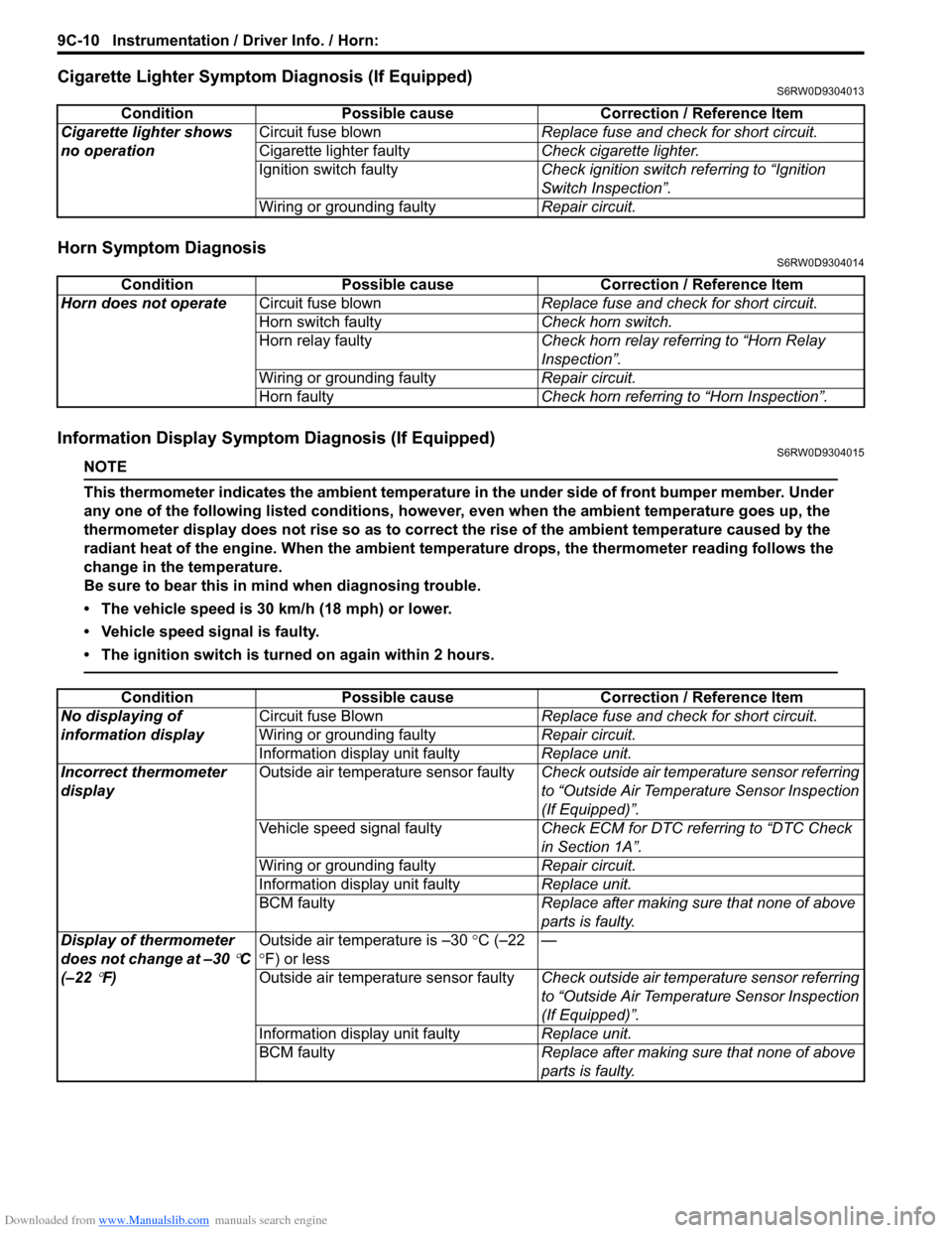
Cigarette Lighter Symptom Diagnosis (If Equipped)S6RW0D9304013
Horn Symptom DiagnosisS6RW0D9304014
Information Display Symptom Diagnosis (If Equipped)S6RW0D9304015
NOTE
This thermometer indicates the ambient temperature in the under side of front bumper member. Under
any one of the following listed conditions, however, even when the ambient temperature goes up, the
thermometer display does not rise so as to correct the rise of the ambient temperature caused by the
radiant heat of the engine. When the ambient temperature drops, the thermometer reading follows the
change in the temperature.
Be sure to bear this in mind when diagnosing trouble.
• The vehicle speed is 30 km/h (18 mph) or lower.
• Vehicle speed signal is faulty.
• The ignition switch is turned on again within 2 hours.
Condition Possible cause Correction / Reference Item
Cigarette lighter shows
no operationCircuit fuse blownReplace fuse and check for short circuit.
Cigarette lighter faultyCheck cigarette lighter.
Ignition switch faultyCheck ignition switch referring to “Ignition
Switch Inspection”.
Wiring or grounding faultyRepair circuit.
Condition Possible cause Correction / Reference Item
Horn does not operateCircuit fuse blownReplace fuse and check for short circuit.
Horn switch faultyCheck horn switch.
Horn relay faultyCheck horn relay referring to “Horn Relay
Inspection”.
Wiring or grounding faultyRepair circuit.
Horn faultyCheck horn referring to “Horn Inspection”.
Condition Possible cause Correction / Reference Item
No displaying of
information displayCircuit fuse BlownReplace fuse and check for short circuit.
Wiring or grounding faultyRepair circuit.
Information display unit faultyReplace unit.
Incorrect thermometer
displayOutside air temperature sensor faultyCheck outside air temperature sensor referring
to “Outside Air Temperature Sensor Inspection
(If Equipped)”.
Vehicle speed signal faultyCheck ECM for DTC referring to “DTC Check
in Section 1A”.
Wiring or grounding faultyRepair circuit.
Information display unit faultyReplace unit.
BCM faultyReplace after making sure that none of above
parts is faulty.
Display of thermometer
does not change at –30
°C
(–22
°F)Outside air temperature is –30 °C (–22
°F) or less—
Outside air temperature sensor faultyCheck outside air temperature sensor referring
to “Outside Air Temperature Sensor Inspection
(If Equipped)”.
Information display unit faultyReplace unit.
BCM faultyReplace after making sure that none of above
parts is faulty.
Page 1363 of 1556
Downloaded from www.Manualslib.com manuals search engine Instrumentation / Driver Info. / Horn: 9C-11
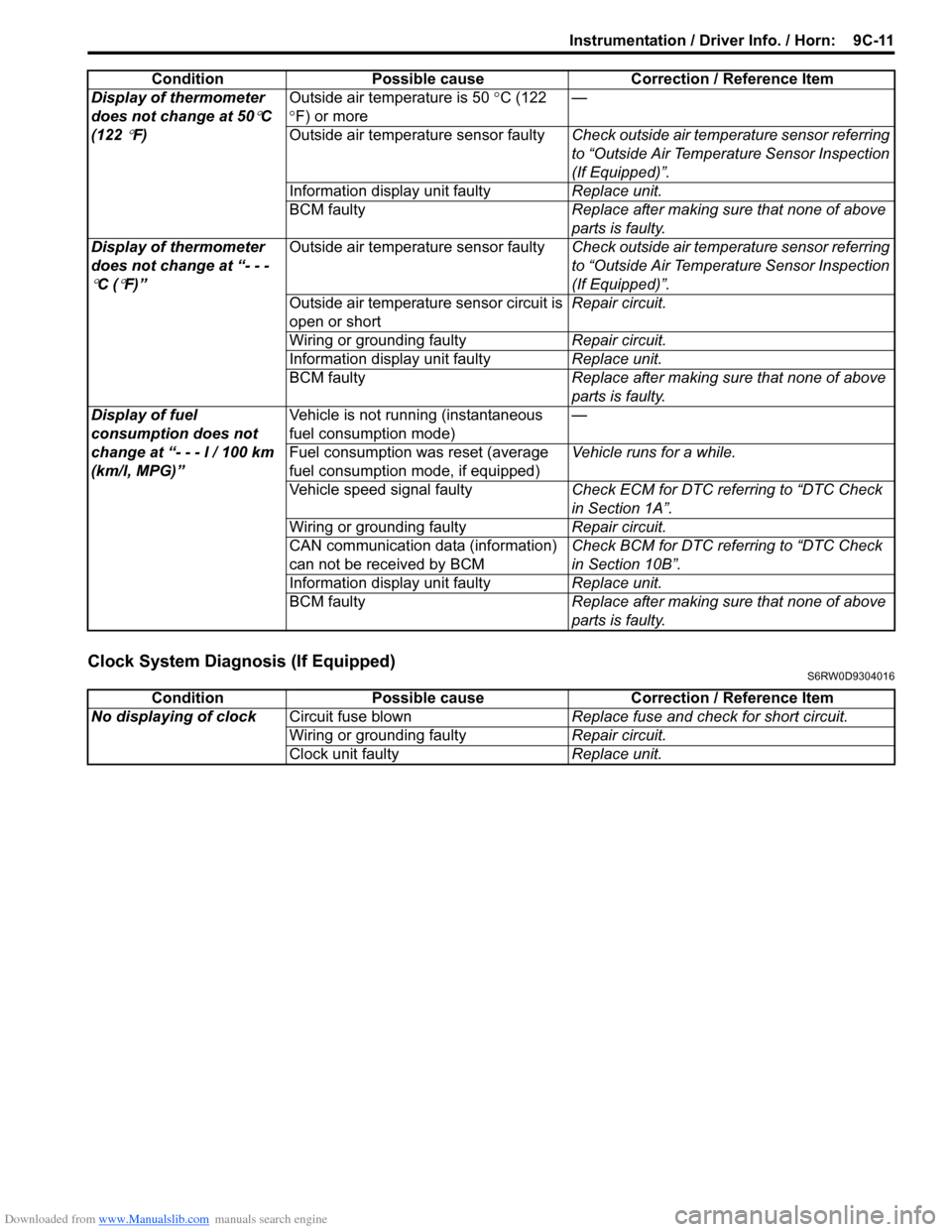
Clock System Diagnosis (If Equipped)S6RW0D9304016
Display of thermometer
does not change at 50
°C
(122
°F)Outside air temperature is 50 °C (122
°F) or more—
Outside air temperature sensor faultyCheck outside air temperature sensor referring
to “Outside Air Temperature Sensor Inspection
(If Equipped)”.
Information display unit faultyReplace unit.
BCM faultyReplace after making sure that none of above
parts is faulty.
Display of thermometer
does not change at “- - -
°C (°F)”Outside air temperature sensor faultyCheck outside air temperature sensor referring
to “Outside Air Temperature Sensor Inspection
(If Equipped)”.
Outside air temperature sensor circuit is
open or shortRepair circuit.
Wiring or grounding faultyRepair circuit.
Information display unit faultyReplace unit.
BCM faultyReplace after making sure that none of above
parts is faulty.
Display of fuel
consumption does not
change at “- - - l / 100 km
(km/l, MPG)”Vehicle is not running (instantaneous
fuel consumption mode)—
Fuel consumption was reset (average
fuel consumption mode, if equipped)Vehicle runs for a while.
Vehicle speed signal faultyCheck ECM for DTC referring to “DTC Check
in Section 1A”.
Wiring or grounding faultyRepair circuit.
CAN communication data (information)
can not be received by BCMCheck BCM for DTC referring to “DTC Check
in Section 10B”.
Information display unit faultyReplace unit.
BCM faultyReplace after making sure that none of above
parts is faulty. Condition Possible cause Correction / Reference Item
Condition Possible cause Correction / Reference Item
No displaying of clockCircuit fuse blownReplace fuse and check for short circuit.
Wiring or grounding faultyRepair circuit.
Clock unit faultyReplace unit.
Page 1368 of 1556
Downloaded from www.Manualslib.com manuals search engine 9C-16 Instrumentation / Driver Info. / Horn:
Engine Coolant Temperature (ECT) Sensor
Inspection
S6RW0D9306008
Check engine coolant temperature sensor for resistance,
refer to “Engine Coolant Temperature (ECT) Sensor
Inspection in Section 1C”.
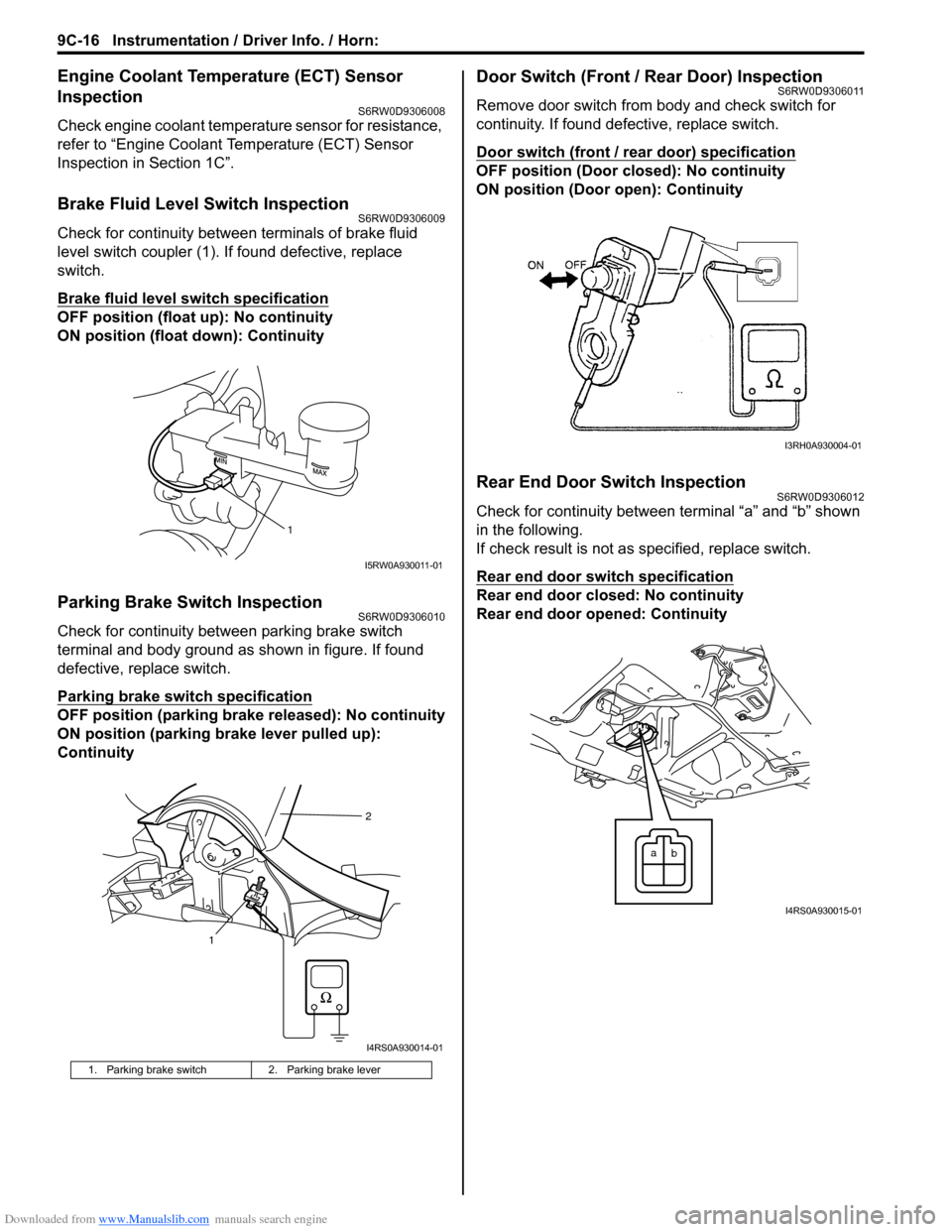
Brake Fluid Level Switch InspectionS6RW0D9306009
Check for continuity between terminals of brake fluid
level switch coupler (1). If found defective, replace
switch.
Brake fluid level switch specification
OFF position (float up): No continuity
ON position (float down): Continuity
Parking Brake Switch InspectionS6RW0D9306010
Check for continuity between parking brake switch
terminal and body ground as shown in figure. If found
defective, replace switch.
Parking brake switch specification
OFF position (parking brake released): No continuity
ON position (parking brake lever pulled up):
Continuity
Door Switch (Front / Rear Door) InspectionS6RW0D9306011
Remove door switch from body and check switch for
continuity. If found defective, replace switch.
Door switch (front / rear door) specification
OFF position (Door closed): No continuity
ON position (Door open): Continuity
Rear End Door Switch InspectionS6RW0D9306012
Check for continuity between terminal “a” and “b” shown
in the following.
If check result is not as specified, replace switch.
Rear end door switch specification
Rear end door closed: No continuity
Rear end door opened: Continuity
1. Parking brake switch 2. Parking brake lever
1
I5RW0A930011-01
12
I4RS0A930014-01
I3RH0A930004-01
a
b
I4RS0A930015-01
Page 1369 of 1556
Downloaded from www.Manualslib.com manuals search engine Instrumentation / Driver Info. / Horn: 9C-17
Outside Air Temperature Sensor Removal and
Installation (If Equipped)
S6RW0D9306013
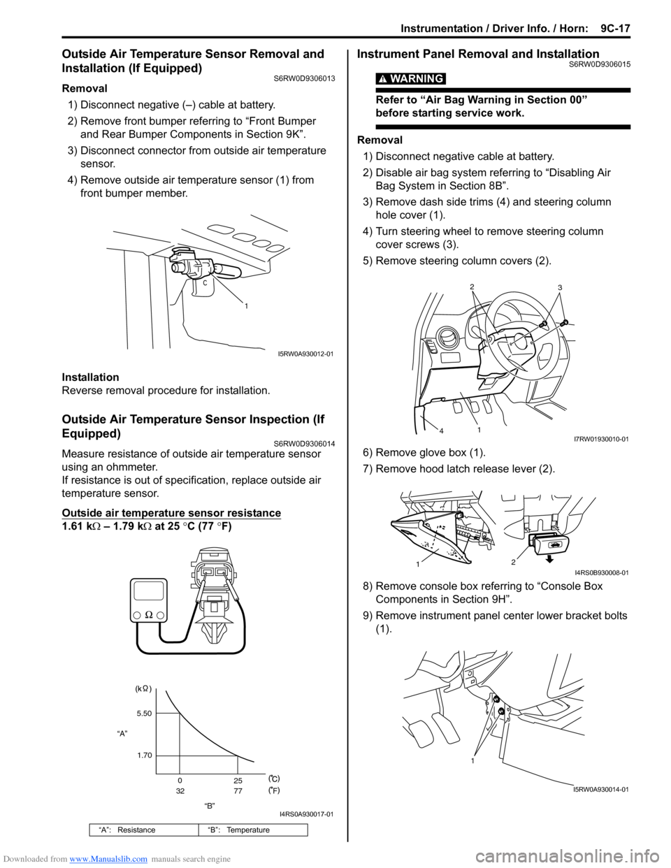
Removal
1) Disconnect negative (–) cable at battery.
2) Remove front bumper referring to “Front Bumper
and Rear Bumper Components in Section 9K”.
3) Disconnect connector from outside air temperature
sensor.
4) Remove outside air temperature sensor (1) from
front bumper member.
Installation
Reverse removal procedure for installation.
Outside Air Temperature Sensor Inspection (If
Equipped)
S6RW0D9306014
Measure resistance of outside air temperature sensor
using an ohmmeter.
If resistance is out of specification, replace outside air
temperature sensor.
Outside air temperature sensor resistance
1.61 kΩ – 1.79 kΩ at 25 °C (77 °F)
Instrument Panel Removal and InstallationS6RW0D9306015
WARNING!
Refer to “Air Bag Warning in Section 00”
before starting service work.
Removal
1) Disconnect negative cable at battery.
2) Disable air bag system referring to “Disabling Air
Bag System in Section 8B”.
3) Remove dash side trims (4) and steering column
hole cover (1).
4) Turn steering wheel to remove steering column
cover screws (3).
5) Remove steering column covers (2).
6) Remove glove box (1).
7) Remove hood latch release lever (2).
8) Remove console box referring to “Console Box
Components in Section 9H”.
9) Remove instrument panel center lower bracket bolts
(1).
“A”: Resistance “B”: Temperature
1
I5RW0A930012-01
“B” “A”5.50
1.70
0
3225
77
F
I4RS0A930017-01
2
3
1
4I7RW01930010-01
2
1I4RS0B930008-01
1
I5RW0A930014-01
Page 1471 of 1556
Downloaded from www.Manualslib.com manuals search engine Table of Contents 10- i
10
Section 10
CONTENTS
Control Systems
Precautions ............................................... 10-1
Precautions........................................................... 10-1
Precautions for Control Systems......................... 10-1
Body Electrical Control System ........... 10B-1
Precautions......................................................... 10B-1
Precautions in Diagnosing Trouble ................... 10B-1
General Description ........................................... 10B-1
BCM General Description ................................. 10B-1
CAN Communication System Description......... 10B-1
Theft Deterrent Light ......................................... 10B-2
Security Alarm Description (If Equipped) .......... 10B-2
Schematic and Routing Diagram ...................... 10B-3
Body Electrical Control System Wiring Circuit
Diagram .......................................................... 10B-3
Connector Layout Diagram of BCM and
Junction Block ................................................. 10B-6
Component Location ......................................... 10B-7
BCM and Related System Component
Location .......................................................... 10B-7
Diagnostic Information and Procedures .......... 10B-8
BCM Self-Diagnosis Function ........................... 10B-8
Body Electrical Control System Check.............. 10B-9
Scan Tool Data ............................................... 10B-11
DTC Table ....................................................... 10B-13
DTC Check ..................................................... 10B-14
DTC Clearance ............................................... 10B-15
BCM Power Circuit and Ground Circuit Check 10B-16
DTC B1133 (DTC No. 1133): Battery Voltage
Too High ....................................................... 10B-17
DTC B1141 / DTC B1142 (No. 1141 / No.
1142) Outside Air Temperature (Ambient
Temp.) Sensor Circuit Malfunction ................ 10B-18
DTC B1150 (No. 1150): Air Bag
Communication Circuit Malfunction .............. 10B-19
DTC B1157 (No. 1157) Air Bag Deployment
Signal Input ................................................... 10B-20
DTC B1170 (No. 1170): EEPROM Access
Error .............................................................. 10B-20
DTC U0073 (No. 0073): Control Module
Communication Bus Off ................................ 10B-20
DTC U0100 (No. 0100): Lost Communication
with ECM....................................................... 10B-20DTC U0101 (No. 0101): Lost Communication
with TCM ....................................................... 10B-20
DTC U0155 (No. 0155): Lost Communication
with Instrument Panel Cluster (IPC) Control
Module .......................................................... 10B-20
DTC U1144 (No. 1144): Lost Communication
with Keyless Start Control Module ................ 10B-20
Inspection of BCM and Its Circuits .................. 10B-21
Repair Instructions ..........................................10B-28
BCM (Included in Junction Block) Removal
and Installation .............................................. 10B-28
Security Alarm Mode Selection Procedure (If
Equipped) ...................................................... 10B-29
Outside Air Temperature Sensor Removal
and Installation .............................................. 10B-29
Outside Air Temperature Sensor Inspection ... 10B-29
Special Tools and Equipment .........................10B-29
Special Tool .................................................... 10B-29
Immobilizer Control System ................. 10C-1
Precautions.........................................................10C-1
Precautions in Diagnosing Troubles .................10C-1
Precaution in Replacing ECM ...........................10C-1
Precaution in Replacing Ignition Key ................10C-1
Precautions in Handling Immobilizer Control
System ............................................................10C-1
General Description ...........................................10C-2
Immobilizer Control System Introduction ..........10C-2
On-Board Diagnostic System Description
(Self-diagnosis Function)................................10C-2
Schematic and Routing Diagram ......................10C-3
Immobilizer Control System Wiring Circuit
Diagram...........................................................10C-3
Component Location .........................................10C-5
Immobilizer Control System Components
Location...........................................................10C-5
Diagnostic Information and Procedures ..........10C-5
Immobilizer Control System Check ...................10C-5
DTC Check........................................................10C-6
DTC Clearance .................................................10C-6
DTC Table .........................................................10C-7
Scan Tool Data .................................................10C-8
Immobilizer Indicator Light Does Not Come
ON with Ignition Switch ON and Engine Stop ..10C-9
Page 1475 of 1556
Downloaded from www.Manualslib.com manuals search engine Body Electrical Control System: 10B-2
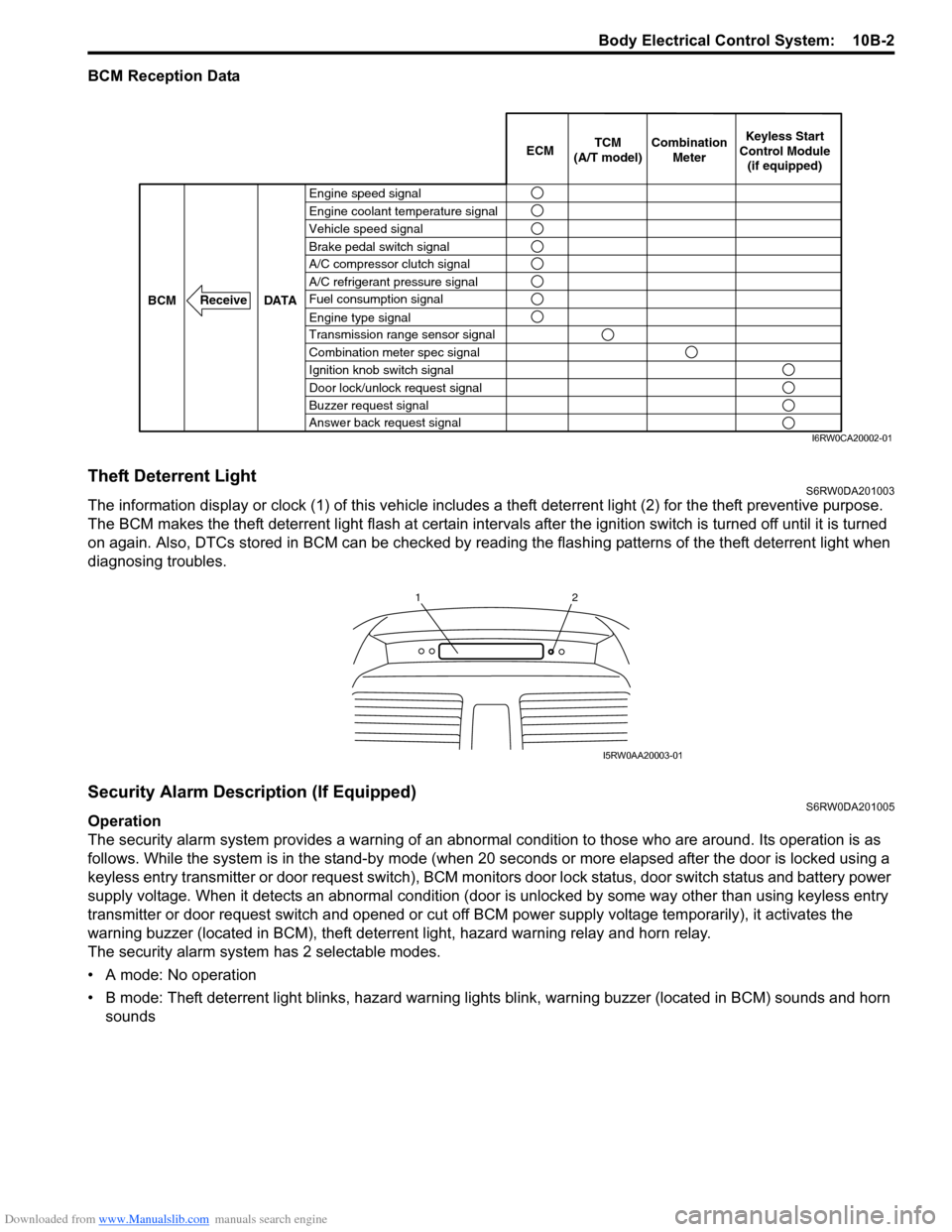
BCM Reception Data
Theft Deterrent LightS6RW0DA201003
The information display or clock (1) of this vehicle includes a theft deterrent light (2) for the theft preventive purpose.
The BCM makes the theft deterrent light flash at certain intervals after the ignition switch is turned off until it is turned
on again. Also, DTCs stored in BCM can be checked by reading the flashing patterns of the theft deterrent light when
diagnosing troubles.
Security Alarm Description (If Equipped)S6RW0DA201005
Operation
The security alarm system provides a warning of an abnormal condition to those who are around. Its operation is as
follows. While the system is in the stand-by mode (when 20 seconds or more elapsed after the door is locked using a
keyless entry transmitter or door request switch), BCM monitors door lock status, door switch status and battery power
supply voltage. When it detects an abnormal condition (door is unlocked by some way other than using keyless entry
transmitter or door request switch and opened or cut off BCM power supply voltage temporarily), it activates the
warning buzzer (located in BCM), theft deterrent light, hazard warning relay and horn relay.
The security alarm system has 2 selectable modes.
• A mode: No operation
• B mode: Theft deterrent light blinks, hazard warning lights blink, warning buzzer (located in BCM) sounds and horn
sounds
Engine speed signal
Vehicle speed signal Engine coolant temperature signal
Brake pedal switch signal
A/C refrigerant pressure signal
Fuel consumption signal A/C compressor clutch signal
Engine type signal
Transmission range sensor signal
Combination meter spec signal
Ignition knob switch signal
Door lock/unlock request signal
Buzzer request signal
Answer back request signal DATA BCM
Receive
Combination
Meter TCM
(A/T model)Keyless Start
Control Module
(if equipped) ECM
I6RW0CA20002-01
12
I5RW0AA20003-01