2006 SUZUKI SX4 air condition
[x] Cancel search: air conditionPage 708 of 1556

Downloaded from www.Manualslib.com manuals search engine 5A-60 Automatic Transmission/Transaxle:
DTC P0962: Pressure Control Solenoid Control Circuit LowS6RW0D5104030
Wiring Diagram
DTC Detecting Condition and Trouble Area
DTC Confirmation Procedure
1) Connect scan tool to DLC with ignition switch OFF, if available.
2) Clear DTC in TCM memory.
3) Start engine.
4) Keep engine running at idle speed for 30 seconds or more.
5) Stop vehicle and check DTC.3Check for pressure control solenoid valve circuit
1) Disconnect TCM connectors.
2) Check for proper connection to TCM at terminals “C06-
2” and “C06-4”. If connection is OK, check circuit for
open, short, and high resistance for the following circuit.
• Between “C06-2” terminal of TCM connector and “LT
GRN/BLK” terminal of valve body harness connector.
• Between “C06-4” terminal of TCM connector and
“GRY” terminal of valve body harness connector.
Are they in good condition?Intermittent trouble or
faulty TCM. Check for
intermittent referring to
“Intermittent and Poor
Connection Inspection
in Section 00”. If OK,
substitute a known-
good TCM and recheck.Repair “LT GRN/BLK”
and/or “GRY” circuit. Step Action Yes No
12V
C06-4
C06-2
GRY
LT GRN/BLK
3
1
2
42
C06C07
[A]
I6RW0B510013-01
1. TCM 3. A/T
2. Pressure control solenoid valve [A]: Terminal arrangement of TCM connector (viewed from harness side)
DTC detecting condition Trouble area
Pressure control solenoid valve output voltage is too low
comparing with TCM command value.• Pressure control solenoid valve circuit open or
shorted to ground
• Malfunction of pressure control solenoid valve
•TCM
Page 719 of 1556

Downloaded from www.Manualslib.com manuals search engine Automatic Transmission/Transaxle: 5A-71
DTC Troubleshooting
Step Action Yes No
1Was “A/T System Check” performed?Go to Step 2. Go to “A/T System
Check”.
2Check TCC solenoid valve resistance
1) Turn ignition switch OFF.
2) Disconnect valve body harness connector (1), (2) on
automatic transaxle.
3) Check for proper connection to terminal at “WHT/BLU”
and “WHT/BLK” circuit.
4) Check resistance of TCC solenoid valve.
TCC solenoid valve resistance
Between terminals of transaxle side valve body
harness connector: 5.0 – 5.6 Ω at 20 °C (68 °F)
Between terminals of transaxle valve body harness
connector and transaxle: Infinity
Is check results satisfactory?Go to Step 3. Replace TCC solenoid
valve or valve body
harness.
3Check for pressure control solenoid valve circuit
1) Disconnect TCM connectors
2) Check for proper connection to TCM at terminals “C06-
3” and “C06-5”. If connection is OK, check circuit for
open, short and high resistance for the following circuit.
• Between “C06-3” terminal of TCM connector and
“WHT/BLK” terminal of valve body harness connector.
• Between “C06-4” terminal of TCM connector and
“WHT/BLU” terminal of valve body harness connector.
Are they in good condition?Intermittent trouble or
faulty TCM. Check for
intermittent referring to
“Intermittent and Poor
Connection Inspection
in Section 00”. If OK,
substitute a known-
good TCM and recheck.Repair “WHT/BLU” and/
or “WHT/BLK” circuit.
1
6 7 8 9
1054
32
2
1
I5RW0C510023-01
Page 730 of 1556

Downloaded from www.Manualslib.com manuals search engine 5A-82 Automatic Transmission/Transaxle:
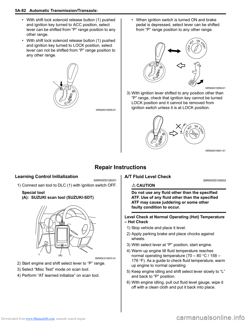
• With shift lock solenoid release button (1) pushed
and ignition key turned to ACC position, select
lever can be shifted from “P” range position to any
other range.
• With shift lock solenoid release button (1) pushed
and ignition key turned to LOCK position, select
lever can not be shifted from “P” range position to
any other range.• When ignition switch is turned ON and brake
pedal is depressed, select lever can be shifted
from “P” range position to any other range.
3) With ignition lever shifted to any position other than
“P” range, check that ignition key cannot be turned
LOCK position and it cannot be removed from
ignition switch unless it is at LOCK position.
Repair Instructions
Learning Control InitializationS6RW0D5106001
1) Connect san tool to DLC (1) with ignition switch OFF.
Special tool
(A): SUZUKI scan tool (SUZUKI-SDT)
2) Start engine and shift select lever to “P” range.
3) Select “Misc Test” mode on scan tool.
4) Perform “AT learned initialize” on scan tool.
A/T Fluid Level CheckS6RW0D5106002
CAUTION!
Do not use any fluid other than the specified
ATF. Use of any fluid other than the specified
ATF may cause juddering or some other
faulty condition to occur.
Level Check at Normal Operating (Hot) Temperature
– Hot Check
1) Stop vehicle and place it level.
2) Apply parking brake and place chocks against
wheels.
3) With select lever at “P” position, start engine.
4) Warm up engine till fluid temperature reaches
normal operating temperature (70 – 80 °C / 158 –
176 °F). As a guide to check fluid temperature, warm
up engine to normal operating.
5) Keep engine idling and shift select lever slowly to “L”
and back to “P” position.
6) With engine idling, pull out fluid level gauge, wipe it
off with a clean cloth and put it back into place.
1
I4RS0A510049-01
I4RS0A510050-01
I4RS0A510051-01
(A) 1I5RW0C510072-01
Page 737 of 1556

Downloaded from www.Manualslib.com manuals search engine Automatic Transmission/Transaxle: 5A-89
2) Turn ignition switch to ACC position.
3) Insert cable casing cap (1) into key cylinder cover (2)
securely.
4) Pull out lock button (1) of select lever side cable end
(2).
5) Shift select lever to “N” position.
NOTE
If select lever is in “P” position, shift select
lever referring to “Select Lever Inspection”.
6) Install cable casing cap (3) to bracket (4).
7) Connect cable end (1) to interlock cam (2) with
ignition switch turned to ACC position.
8) Drive lock button (5) in cable end until it locks cable
expansion and contraction.9) With select lever set at “P” position, turn ignition key
to ACC position and then check for the following
conditions.
• With knob button released, ignition key can be
turned from ACC position to LOCK position.
• With knob button pressed, ignition key cannot be
turned from ACC position to LOCK position.
10) Install knee protector to steering column.
11) Install steering column cover.
12) If the vehicle is equipped with air bag system,
connect negative cable at battery and enable air bag
system, referring to “Enabling Air Bag System in
Section 8B”.
Transmission Range Sensor Inspection and
Adjustment
S6RW0D5106009
1) Shift manual select lever (4) to “N” range.
2) Check that needle direction shaped on lock washer
(2) and “N” reference line (1) on transmission range
sensor are aligned. If not, loosen sensor bolts (3)
and align them.
Tightening torque
Transmission range sensor bolt (a): 5.5 N·m (
0.55 kgf-m, 4.0 lb-ft)
2
1I5RW0C510047-01
1 1
2
I2RH01510086-01
3
4 12
3 5
I5RW0C510048-01
1
3, (a) 4
2
I2RH0B510041-01
Page 742 of 1556

Downloaded from www.Manualslib.com manuals search engine 5A-94 Automatic Transmission/Transaxle:
4) Install oil strainer assembly (1).
Tightening torque
Oil strainer bolt (a): 10 N·m (1.0 kgf-m, 7.5 lb-ft)
5) Install new oil pan gasket (1) and oil pan (2).
6) Tighten oil pan bolts to specified torque diagonally
and little by little.
Tightening torque
Oil pan bolt (b): 7.0 N·m (0.7 kgf-m, 5.0 lb-ft)
7) Install left side engine under cover.
8) Lower vehicle.
9) Connect negative cable at battery.
Solenoid Valves (Shift Solenoid Valves and
Timing Solenoid Valve) Inspection
S6RW0D5106062
Resistance Check
Check shift solenoid valves and timing solenoid valve.
Shift solenoid valves and timing solenoid valve
resistance
Standard: 11 – 15 Ω at 20 °C (68 °F)Operation Check
Shift solenoid valve-A (No.1) and -B (No.2)
CAUTION!
• Do not insert air gun against strainer
installed on inlet of solenoid valve too
deeply, when blowing air into solenoid
valve. If not, the strainer will be damaged.
• Be very careful as dust etc. does not enter
when solenoid valves are inspected.
• Check that solenoid valve (1) actuate with click sound
when battery voltage is conducted.
• When solenoid valve (1) is connected to battery (2),
confirm that solenoid valve is close condition by
blowing air (50 – 200 kPa, 0.5 – 2.0 kg/cm
2, 7 – 28.5
psi) into solenoid valve as shown in figure.
• When solenoid valve (1) is not connected to battery
(2), confirm that solenoid valve is open condition by
blowing air (50 – 200 kPa, 0.5 – 2.0 kg/cm
2, 7 – 28.5
psi) into solenoid valve as shown in figure.
NOTE
Do not fail to inspect with air to prevent
mistaken checking because return spring for
valve is not installed into solenoid valve.
I2RH0B510059-01
I2RH0B510060-01
I2RH0B510061-01
I2RH0B510062-01
Page 743 of 1556

Downloaded from www.Manualslib.com manuals search engine Automatic Transmission/Transaxle: 5A-95
Timing solenoid valve
CAUTION!
• Do not insert air gun against strainer
installed on inlet of solenoid valve too
deeply, when blowing air into solenoid
valve. If not, the strainer will be damaged.
• Be very careful as dust etc. does not enter
when solenoid valves are inspected.
• Check that solenoid valve (1) actuate with click sound
when battery voltage is conducted.
• When timing solenoid valve (1) is connected to battery
(2), confirm that timing solenoid valve is open
condition by blowing air (50 – 200 kPa, 0.5 – 2.0 kg/
cm
2, 7 – 28.5 psi) into solenoid valve as shown in
figure.
• When timing solenoid valve (1) is not connected to
battery (2), confirm that timing solenoid valve is close
condition by blowing air (50 – 200 kPa, 0.5 – 2.0 kg/
cm
2, 7 – 28.5 psi) into solenoid valve as shown in
figure.
NOTE
Do not fail to inspect with air to prevent
mistaken checking because return spring for
valve is not installed into solenoid valve.
Pressure Control Solenoid Valves (Pressure
Control Solenoid and TCC Solenoid) Removal
and Installation
S6RW0D5106063
Removal
1) Disconnect negative cable at battery.
2) Lift up vehicle.
3) Remove left side engine under cover.
4) Remove drain plug and drain A/T fluid.
5) Install drain plug.
Tightening torque
A/T fluid drain plug: 17 N·m (1.7 kgf-m, 12.5 lb-ft)
6) Remove A/T oil pan (1) and oil pan gasket (2).
7) Remove oil strainer assembly (3).
8) Remove transmission fluid temperature sensor (1)
from sensor clamp.
9) Disconnect solenoid connectors (2).
I2RH0B510063-01
I2RH0B510054-01
2
1
I5RW0C510038-02
Page 817 of 1556

Downloaded from www.Manualslib.com manuals search engine Manual Transmission/Transaxle: 5B-5
Diagnostic Information and Procedures
Manual Transaxle Symptom DiagnosisS6RW0D5204001
Repair Instructions
Manual Transaxle Oil Level CheckS6RW0D5206001
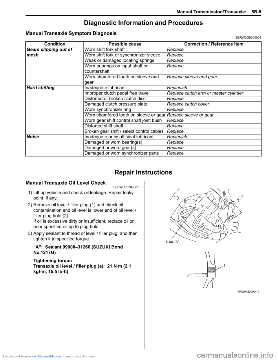
1) Lift up vehicle and check oil leakage. Repair leaky
point, if any.
2) Remove oil level / filler plug (1) and check oil
contamination and oil level is lower end of oil level /
filler plug hole (2).
If oil is excessive dirty or insufficient, replace oil or
pour specified oil up to plug hole.
3) Apply sealant to thread of level / filler plug, and then
tighten it to specified torque.
“A”: Sealant 99000–31260 (SUZUKI Bond
No.1217G)
Tightening torque
Transaxle oil level / filler plug (a): 21 N·m (2.1
kgf-m, 15.5 lb-ft)Condition Possible cause Correction / Reference Item
Gears slipping out of
meshWorn shift fork shaftReplace
Worn shift fork or synchronizer sleeveReplace
Weak or damaged locating springsReplace
Worn bearings on input shaft or
countershaftReplace
Worn chamfered tooth on sleeve and
gearReplace sleeve and gear
Hard shiftingInadequate lubricantReplenish
Improper clutch pedal free travelReplace clutch arm or master cylinder
Distorted or broken clutch discReplace
Damaged clutch pressure plateReplace clutch cover
Worn synchronizer ringReplace
Worn chamfered tooth on sleeve or gearReplace sleeve or gear
Worn gear shift control shaft joint bushReplace
Distorted shift shaftReplace
Broken gear shift / select control cablesReplace
NoiseInadequate or insufficient lubricantReplenish
Damaged or worn bearing(s)Replace
Damaged or worn gear(s)Replace
Damaged or worn synchronizer partsReplace
I5RW0A520004-01
Page 855 of 1556

Downloaded from www.Manualslib.com manuals search engine Clutch: 5C-2
Diagnostic Information and Procedures
Clutch System Symptom DiagnosisS6RW0D5304001
Condition Possible cause Correction / Reference Item
SlippingImproper clutch pedal free travelBleed air or replace master cylinder.
Worn or oily clutch disc facingReplace disc.
Warped disc, pressure plate or flywheel
surfaceReplace disc, clutch cover or flywheel.
Weakened diaphragm springReplace clutch cover.
Master cylinder piston or seal cup not
returningReplace master cylinder.
Dragging clutchImproper clutch pedal free travelBleed air or replace master cylinder.
Weakened diaphragm spring, or worn
spring tipReplace clutch cover.
Rusted input shaft splinesLubricate.
Damaged or worn splines of transaxle
input shaftReplace input shaft.
Excessively wobbly clutch discReplace disc.
Clutch facings broken or dirty with oilReplace disc.
Fluid leakageRepair or replace.
Clutch vibrationGlazed (glass-like) clutch facingsRepair or replace disc.
Clutch facings dirty with oilReplace disc.
Release bearing slides unsmoothlyReplace clutch operating cylinder assembly.
Wobbly clutch disc, or poor facing
contactReplace disc.
Weakened torsion springs in clutch discReplace disc.
Clutch disc rivets looseReplace disc.
Distorted pressure plate or flywheel
surfaceReplace clutch cover or flywheel.
Weakened engine mountingReplace engine mounting.
Loosened engine mounting bolt or nutRetighten engine mounting bolt or nut.
Noisy clutchWorn or broken release bearingReplace clutch operating cylinder assembly.
Input shaft front bearing worn downReplace input shaft bearing.
Excessive rattle of clutch disc hubReplace disc.
Cracked clutch discReplace disc.
Pressure plate and diaphragm spring
rattlingReplace clutch cover.
Grabbing clutchClutch disc facings soaked with oilReplace disc.
Clutch disc facings excessively wornReplace disc.
Rivet heads showing out of facingReplace disc.
Weakened torsion springsReplace disc.