2006 SUZUKI SX4 heating
[x] Cancel search: heatingPage 372 of 1556

Downloaded from www.Manualslib.com manuals search engine 1F-7 Engine Cooling System:
Thermostat Removal and InstallationS6RW0D1606007
Removal
1) Drain coolant referring to “Cooling System Draining”.
2) Remove intake manifold referring to “Intake Manifold
Removal and Installation in Section 1D”.
3) Disconnect water hose (1) and heater hose (2) from
each pipe.
4) Remove thermostat case (3) with thermostat cap (4)
and water inlet pipe (5).
5) Remove water inlet pipe with thermostat cap from
thermostat case.
6) Remove thermostat from thermostat case (3).
Installation
Reverse removal procedure for installation noting the
following points.
• Install thermostat (5) to thermostat case (2) by
aligning air bleed valve (4) of thermostat with mark (3)
of thermostat case and, then install thermostat cap (1)
to thermostat case.
• Use new O-rings when installing.
• Refill cooling system referring to Step 7) to 17) of
“Cooling System Flush and Refill”.
• Verify that there is no coolant leakage at each
connection.
Thermostat InspectionS6RW0D1606008
• Make sure that air bleed valve (1) of thermostat is
clean.
• Check to make sure that valve seat (2) is free from
foreign matters which would prevent valve from
seating tight.
• Check thermostat seal (3) for breakage, deterioration
or any other damage.
• Check thermostatic movement of wax pellet as
follows:
a. Immerse thermostat (1) in water, and heat water
gradually.
b. Check that valve starts to open at specific
temperature.
Temperature at which valve begins to open
80 – 84 °C (176 – 183 °F)
Temperature at which valve become fully open
95 – 97 °C (203 – 206 °F)
Va l v e l i ft
More than 8 mm (0.31 in.) at 95 °C (203 °F)
If valve starts to open at a temperature substantially
below or above specific temperature, thermostat unit
should be replaced with a new one. Such a unit, if
reused, will bring about overcooling or overheating
tendency.
I6RW0B160007-01
4
53
12
I6RW0B160008-01
2. Thermometer 3. Heater
I3RM0A160008-01
I2RH01160012-01
Page 428 of 1556

Downloaded from www.Manualslib.com manuals search engine 1K-1 Exhaust System:
Engine
Exhaust System
General Description
Exhaust System DescriptionS6RW0D1B01001
The exhaust system consists of an exhaust manifold, three-way catalytic converter (TWC) in catalyst case, exhaust
pipes, a muffler and seals, gasket and etc.
The three-way catalytic converter is an emission control device added to the exhaust system to lower the levels of
Hydrocarbon (HC), Carbon Monoxide (CO), and Oxides of Nitrogen (NOx) pollutants in the exhaust gas.
Diagnostic Information and Procedures
Exhaust System CheckS6RW0D1B04001
WARNING!
To avoid the danger of being burned, do not touch the exhaust system when the system is hot. Any
service on the exhaust system should be performed when the system is cool.
At every interval of periodic maintenance service, and when vehicle is raised for other service, check exhaust system
as follows:
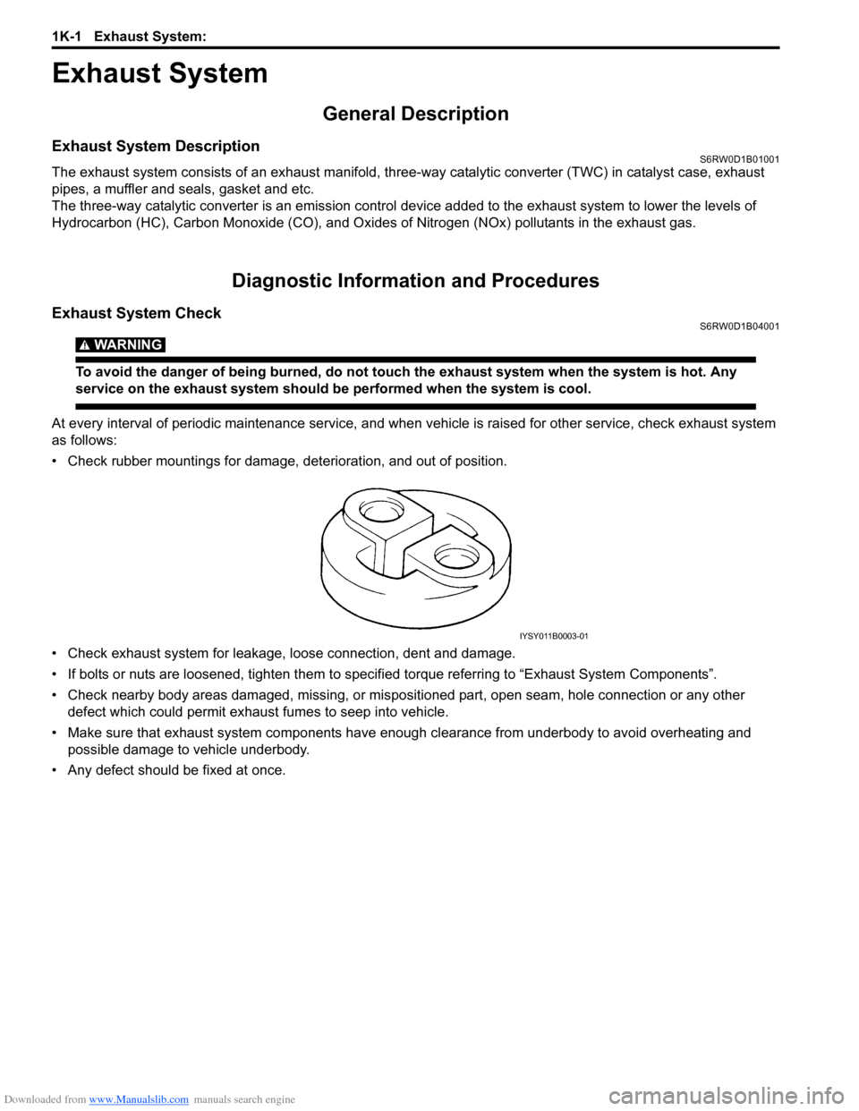
• Check rubber mountings for damage, deterioration, and out of position.
• Check exhaust system for leakage, loose connection, dent and damage.
• If bolts or nuts are loosened, tighten them to specified torque referring to “Exhaust System Components”.
• Check nearby body areas damaged, missing, or mispositioned part, open seam, hole connection or any other
defect which could permit exhaust fumes to seep into vehicle.
• Make sure that exhaust system components have enough clearance from underbody to avoid overheating and
possible damage to vehicle underbody.
• Any defect should be fixed at once.
IYSY011B0003-01
Page 471 of 1556

Downloaded from www.Manualslib.com manuals search engine Wheels and Tires: 2D-2
Replacement Tires
When replacement is necessary, the original equipment
type tire should be used. Refer to the Tire Placard.
Replacement tires should be of the same size, load
range and construction as those originally on the vehicle.
Use of any other size or type tire may affect ride,
handling, speedometer / odometer calibration, vehicle
ground clearance and tire or snow chain clearance to the
body and chassis.
It is recommended that new tires be installed in pairs on
the same axle. If necessary to replace only one tire, it
should be paired with the tire having the most tread, to
equalize braking traction.
WARNING!
Do not mix different types of tires on the
same vehicle such as radial, bias and bias-
belted tires except in emergencies, because
handling may be seriously affected and may
result in loss of control.
The metric term for tire inflation pressure is the kilo
pascal (kPa). Tire pressures is usually printed in both
kPa and kgf/cm
2 on the “Tire Placard”.
Metric tire gauges are available from tool suppliers.
The chart, shown in the table, converts commonly used
inflation pressures from kPa to kgf/cm
2 and psi.
Wheels DescriptionS6RW0D2401002
Wheel Maintenance
Wheel repairs that use welding, heating, or peening are
not approved. All damaged wheels should be replaced.
Replacement Wheels
Wheels must be replaced if they are bent, dented, have
excessive lateral or radial runout, air leak through welds,
have elongated bolt holes, if lug wheel bolts won’t stay
tight, or if they are heavily rusted. Wheels with greater
runout than shown in the following may cause
objectional vibrations.
Replacement wheels must be equivalent to the original
equipment wheels in load capacity, diameter, rim with
offset and mounting configuration. A wheel of improper
size or type may affect wheel and bearing life, brake
cooling, speedometer / odometer calibration, vehicle
ground clearance and tire clearance to body and
chassis.How to Measure Wheel Runout
To measure the wheel runout, it is necessary to use an
accurate dial indicator. The tire may be on or off the
wheel. The wheel should be installed to the wheel
balancer of the like for proper measurement.
Take measurements of both lateral runout “a” and radial
runout “b” at both inside and outside of the rim flange.
With the dial indicator set in place securely, turn the
wheel one full revolution slowly and record every reading
of the indicator.
When the measured runout exceeds the specification
and correction by the balancer adjustment is impossible,
replace the wheel. If the reading is affected by welding,
paint or scratch, it should be ignored.
Lateral runout limit “a”
Aluminum wheel: 0.3 mm (0.012 in.)
Steel wheel: 0.9 mm (0.035 in.)
Radial runout limit “b”
Aluminum wheel: 0.3 mm (0.012 in.)
Steel wheel: 0.7 mm (0.028 in.)
Metric Lug Nuts and Wheel Studs
All models use metric lug nuts and wheel studs.
Metric lug nuts and wheel studs size
M12 x 1.25
If a broken stud is found, see “Front Wheel Hub, Disc,
Bolt and Bearing Check in Section 2B”, “Front Wheel
Hub, Steering Knuckle and Wheel Bearing Removal and
Installation in Section 2B”, “Rear Wheel Hub Assembly
Removal and Installation in Section 2C”. kPa kgf/cm
2psi
Conversion: 1 psi =
6.895 kPa 1 kgf/cm
2 =
98.066 kPa160 1.6 23
180 1.8 26
200 2.0 29
220 2.2 32
240 2.4 35
260 2.6 38
280 2.8 41
300 3.0 44
320 3.2 47
340 3.4 50I4RS0A240001-01
I2RH01240003-01
Page 529 of 1556

Downloaded from www.Manualslib.com manuals search engine Differential: 3B-32
Coupling Air Temperature Sensor InspectionS6RW0D3206007
CAUTION!
Do not heat up coupling air temperature
sensor more than 100 °C (212 °F). Otherwise,
coupling air temperature sensor will be
damaged.
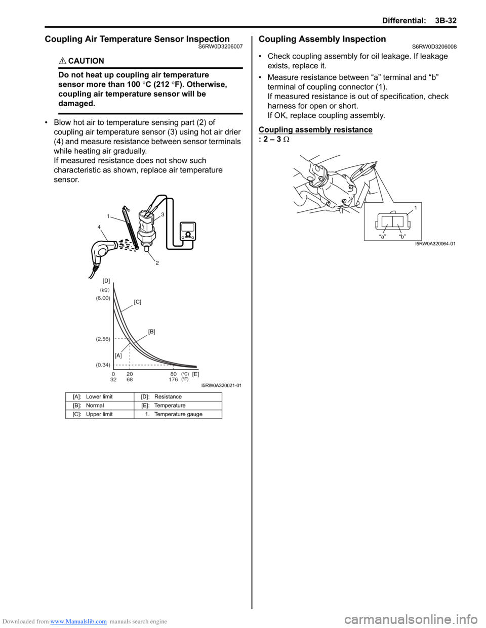
• Blow hot air to temperature sensing part (2) of
coupling air temperature sensor (3) using hot air drier
(4) and measure resistance between sensor terminals
while heating air gradually.
If measured resistance does not show such
characteristic as shown, replace air temperature
sensor.
Coupling Assembly InspectionS6RW0D3206008
• Check coupling assembly for oil leakage. If leakage
exists, replace it.
• Measure resistance between “a” terminal and “b”
terminal of coupling connector (1).
If measured resistance is out of specification, check
harness for open or short.
If OK, replace coupling assembly.
Coupling assembly resistance
: 2 – 3 Ω
[A]: Lower limit [D]: Resistance
[B]: Normal [E]: Temperature
[C]: Upper limit 1. Temperature gauge
020
32 68 17680 (6.00)
(0.34) (2.56)
1
4
23
[D]
[C]
[B]
[A]
[E]
I5RW0A320021-01
1
“a” “b”I5RW0A320064-01
Page 784 of 1556

Downloaded from www.Manualslib.com manuals search engine 5A-136 Automatic Transmission/Transaxle:
Differential Assembly Disassembly and
Reassembly
S6RW0D5106053
Disassembly
1) Remove final gear bolts (1), and then final gear (2).
2) Remove differential side RH bearing by using special
tools.
Special tool
(A): 09926–37610
(B): 09926–37610–001
(C): 09926–37610–003
(D): 09926–37610–002
3) Remove output shaft speed sensor (VSS) drive gear
(1).4) Remove differential side LH bearing by using special
tools.
Special tool
(A): 09926–37610
(B): 09926–37610–001
(C): 09926–37610–003
(D): 09926–37610–002
Reassembly
WARNING!
• When taking warmed final driven gear out
of vessel, use tongs or the like. Taking out
it with bare hand will cause severe burn.
• While installing warmed final driven gear,
use oven glove such as leather glove.
Picking up it with bare hand may cause
burn.
CAUTION!
Do not leave final driven gear in boiling water
for longer than 5 min. Overheating the gear
may cause strength reduction of gear.
1) Put final driven gear in water vessel, heat and
remove when it boils, then remove moisture.
NOTE
After removing moisture on final driven gear,
install final driven gear to differential case as
quickly as possible.
2. Differential case subassembly
I2RH0B510225-01
I2RH0B510226-01
I2RH0B510227-01
I2RH0B510228-01
I2RH0B510229-01