2006 SUZUKI SX4 fuses
[x] Cancel search: fusesPage 997 of 1556

Downloaded from www.Manualslib.com manuals search engine Air Conditioning System: Automatic Type 7B-57
SUN LOAD (W/m2): This parameter indicates the
amount of sunlight detected by sunload sensor.
MODE CONT SWITCH (Air flow selector position,
AUTO, FACE, B/L, FOOT, D/F, DEF): This
parameter indicates the selected position of air flow
selector.
FAN CONT SWITCH (Blower speed selector, AUTO,
OFF, 1st – 8th): This parameter indicates the
selected position of blower speed selector.
FAN DESIRE VOLT (Fan desired voltage, V): This
parameter indicates the consumption voltage of
blower motor.
AIR MIX POS SENSOR (Temperature control
actuator position sensor, V): This parameter
indicates the input signal from position sensor in
temperature control actuator.
MODE POS SENSOR (Air flow control actuator
position sensor, V): This parameter indicates the
input signal from position sensor in air flow control
actuator.
A/C CONT SIG (A/C control signal, ON, OFF): This
parameter indicates the state of A/C switch.BLOWER LOAD SIG (Blower fan load signal, ON,
OFF): ON: Position of blower speed selector is 1st
position or more.
OFF: Position of blower speed selector is OFF
position.
AIR INTAKE MODE (Air intake selector position,
AUTO, FRE, REC): This parameter indicates the
selected position of air intake selector.
REFRIGERANT PRESSURE (A/C refrigerant absolute
pressure, kPa): This parameter indicates the A/C
refrigerant absolute pressure calculated by ECM
A/C COMP CLUCH (A/C compressor magnet clutch,
ON, OFF): This parameter indicates the state of the
A/C compressor magnet clutch.
VEHICLE SPEED (km/h, mph): This parameter
indicates the vehicle speed calculated by ECM.
ENGINE TYPE (Engine type signal, J20, M16 or
M15): This parameter indicates the engine type
signal transmitted by ECM.
METER SPEC (Combination meter spec signal, EU,
UK, US, Canada, DOM): This parameter indicates
the combination meter spec signal transmitted by
combination meter.
Visual InspectionS6RW0D7224009
Check visually the following parts and systems.
DTC B1502: Inside Air Temperature Sensor Circuit MalfunctionS6RW0D7224010
Wiring DiagramInspection item Correction
• Refrigerant leakage and amount
• A/C pipe or hose disconnection,
looseness and
deterioration
• A/C compressor drive belt looseness and damageRefer to “Compressor Drive Belt Inspection
and Adjustment”.
• Battery fluid level and corrosion
of terminal
• Connectors of electric wire harness disconnection and
friction
• Fuses burning
• Parts installation and damage
• Other parts that can be checked visually
5V
G20
1 2 3 4 5 6 7 8 9 10 11 12 13 14
15 16 17 18 19 20 21 24 23 22 25 26 27 28 29 30
ORNORNPNK/BLKG20-10
21
3 [S]
[G]
G20-24
I7RW01722004-01
[S]: Inside air temperature sensor signal circuit 1. HVAC control module 3. To other sensors
[G]: Inside air temperature sensor ground circuit 2. Inside air temperature sensor
Page 1161 of 1556
Downloaded from www.Manualslib.com manuals search engine Table of Contents 9- i
9
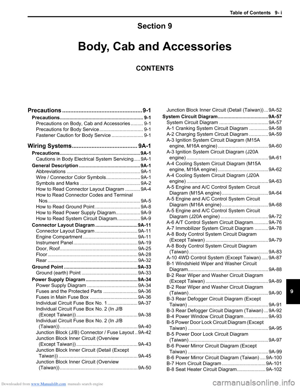
Section 9
CONTENTS
Body, Cab and Accessories
Precautions ................................................. 9-1
Precautions............................................................. 9-1
Precautions on Body, Cab and Accessories ......... 9-1
Precautions for Body Service ................................ 9-1
Fastener Caution for Body Service ....................... 9-1
Wiring Systems........................................ 9A-1
Precautions........................................................... 9A-1
Cautions in Body Electrical System Servicing..... 9A-1
General Description ............................................. 9A-1
Abbreviations ...................................................... 9A-1
Wire / Connector Color Symbols ......................... 9A-1
Symbols and Marks ............................................ 9A-2
How to Read Connector Layout Diagram ........... 9A-4
How to Read Connector Codes and Terminal
Nos.................................................................... 9A-5
How to Read Ground Point ................................. 9A-8
How to Read Power Supply Diagram.................. 9A-9
How to Read System Circuit Diagram................. 9A-9
Connector Layout Diagram ............................... 9A-11
Connector Layout Diagram ............................... 9A-11
Engine Compartment ........................................ 9A-11
Instrument Panel ............................................... 9A-19
Door, Roof......................................................... 9A-25
Floor .................................................................. 9A-28
Rear .................................................................. 9A-32
Ground Point ...................................................... 9A-33
Ground (earth) Point ......................................... 9A-33
Power Supply Diagram ...................................... 9A-34
Power Supply Diagram ..................................... 9A-34
Fuses and the Protected Parts ......................... 9A-36
Fuses in Main Fuse Box ................................... 9A-36
Individual Circuit Fuse Box No. 1 ...................... 9A-37
Individual Circuit Fuse Box No. 2 (In J/B
(Except Taiwan)) ............................................. 9A-38
Individual Circuit Fuse Box No. 2 (In J/B
(Taiwan)) ......................................................... 9A-40
Junction Block (J/B) Connector / Fuse Layout .. 9A-42
Junction Block Inner Circuit (Overview
(Except Taiwan)) ............................................. 9A-43
Junction Block Inner Circuit (Detail (Except
Taiwan)) .......................................................... 9A-45
Junction Block Inner Circuit (Overview
(Taiwan)) ......................................................... 9A-50Junction Block Inner Circuit (Detail (Taiwan)) ... 9A-52
System Circuit Diagram.....................................9A-57
System Circuit Diagram .................................... 9A-57
A-1 Cranking System Circuit Diagram .............. 9A-58
A-2 Charging System Circuit Diagram .............. 9A-59
A-3 Ignition System Circuit Diagram (M15A
engine, M16A engine) ..................................... 9A-60
A-3 Ignition System Circuit Diagram (J20A
engine) ............................................................ 9A-61
A-4 Cooling System Circuit Diagram (M15A
engine, M16A engine) ..................................... 9A-62
A-4 Cooling System Circuit Diagram (J20A
engine) ............................................................ 9A-63
A-5 Engine and A/C Control System Circuit
Diagram (M15A engine) .................................. 9A-64
A-5 Engine and A/C Control System Circuit
Diagram (M16A engine) .................................. 9A-68
A-5 Engine and A/C Control System Circuit
Diagram (J20A engine) ................................... 9A-72
A-6 A/T Control System Circuit Diagram........... 9A-76
A-7 Immobilizer System Circuit Diagram .......... 9A-78
A-8 Body Control System Circuit Diagram
(Except Taiwan) .............................................. 9A-79
A-8 Body Control System Circuit Diagram
(Taiwan) .......................................................... 9A-83
A-10 4WD Control System (Except Taiwan) ..... 9A-87
B-1 Windshield Wiper and Washer Circuit
Diagram........................................................... 9A-88
B-2 Rear Wiper and Washer Circuit Diagram
(Except Taiwan) .............................................. 9A-89
B-2 Rear Wiper and Washer Circuit Diagram
(Taiwan) .......................................................... 9A-90
B-3 Rear Defogger Circuit Diagram (Except
Taiwan) ........................................................... 9A-91
B-3 Rear Defogger Circuit Diagram (Taiwan) ... 9A-92
B-4 Power Window Circuit Diagram .................. 9A-93
B-5 Power Door Lock Circuit Diagram (Except
Taiwan) ........................................................... 9A-95
B-5 Power Door Lock Circuit Diagram
(Taiwan) .......................................................... 9A-97
B-6 Power Mirror Circuit Diagram (Except
Taiwan) ........................................................... 9A-99
B-6 Power Mirror Circuit Diagram (Taiwan) .... 9A-100
B-7 Horn Circuit Diagram ................................ 9A-101
B-8 Seat Heater Circuit Diagram..................... 9A-102
Page 1203 of 1556
Downloaded from www.Manualslib.com manuals search engine Wiring Systems: 9A-36
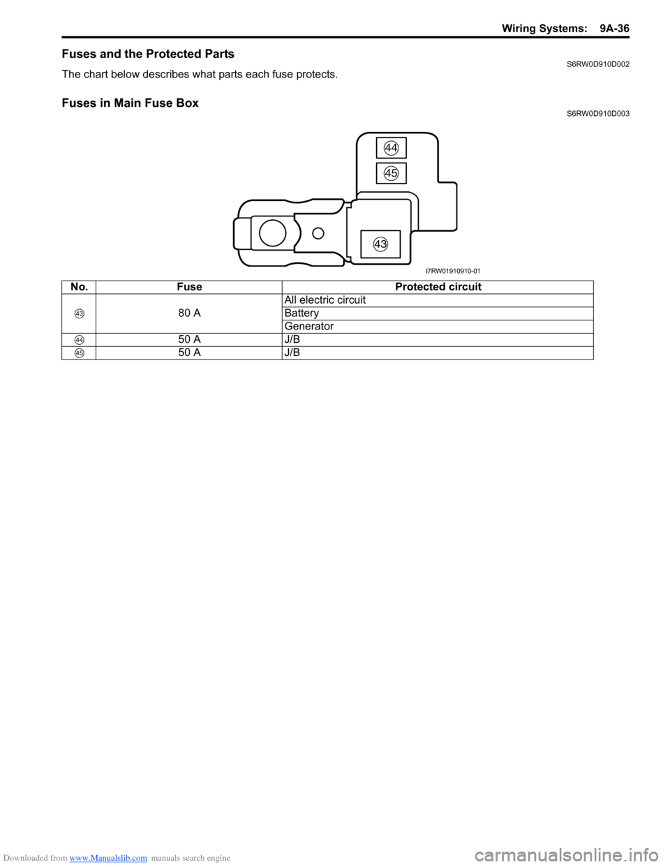
Fuses and the Protected PartsS6RW0D910D002
The chart below describes what parts each fuse protects.
Fuses in Main Fuse BoxS6RW0D910D003
No. Fuse Protected circuit
80 AAll electric circuit
Battery
Generator
50 A J/B
50 A J/B
43
45
44
I7RW01910910-01
Page 1204 of 1556
Downloaded from www.Manualslib.com manuals search engine 9A-37 Wiring Systems:
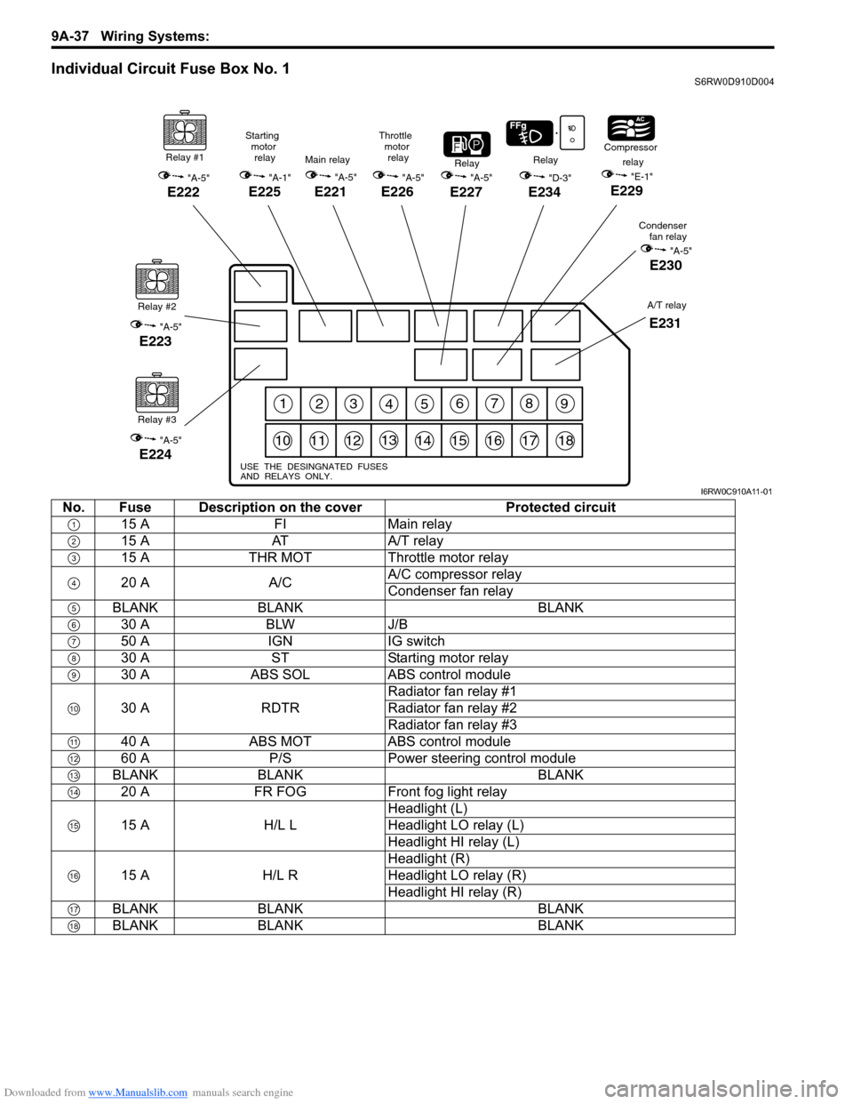
Individual Circuit Fuse Box No. 1S6RW0D910D004
123456789
101112131415161718
USE THE DESINGNATED FUSES
AND RELAYS ONLY.
Relay #1
"A-5"
E222
Relay #2
"A-5"
E223
Relay #3
"A-5"
E224
"A-5"
E227
RelayRelay
"D-3"
E234
Compressor
relay
"E-1"
E229
Condenser
fan relay
"A-5"
E230
Main relay
"A-5"
E221
Starting
motor
relay
"A-1"
E225
Throttle
motor
relay
"A-5"
E226
A/T relay
E231
I6RW0C910A11-01
No. Fuse Description on the cover Protected circuit
15 A FI Main relay
15 A AT A/T relay
15 A THR MOT Throttle motor relay
20 A A/CA/C compressor relay
Condenser fan relay
BLANK BLANK BLANK
30 A BLW J/B
50 A IGN IG switch
30 A ST Starting motor relay
30 A ABS SOL ABS control module
30 A RDTRRadiator fan relay #1
Radiator fan relay #2
Radiator fan relay #3
40 A ABS MOT ABS control module
60 A P/S Power steering control module
BLANK BLANK BLANK
20 A FR FOG Front fog light relay
15 A H/L LHeadlight (L)
Headlight LO relay (L)
Headlight HI relay (L)
15 A H/L RHeadlight (R)
Headlight LO relay (R)
Headlight HI relay (R)
BLANK BLANK BLANK
BLANK BLANK BLANK
Page 1205 of 1556
Downloaded from www.Manualslib.com manuals search engine Wiring Systems: 9A-38
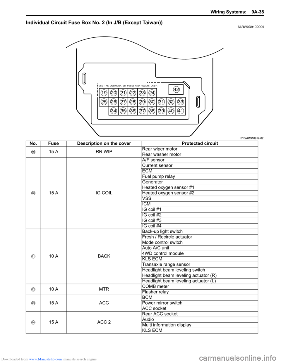
Individual Circuit Fuse Box No. 2 (In J/B (Except Taiwan))S6RW0D910D009
19
25
20
26
34
21
27
35
22
28
36
23
29
37
24
30
38
31
39
32
40
33
41
42USE THE DESINGNATED FUSES AND RELAYS ONLY.
I7RW01910912-02
No. Fuse Description on the cover Protected circuit
15 A RR WIPRear wiper motor
Rear washer motor
15 A IG COILA/F sensor
Current sensor
ECM
Fuel pump relay
Generator
Heated oxygen sensor #1
Heated oxygen sensor #2
VSS
ICM
IG coil #1
IG coil #2
IG coil #3
IG coil #4
10 A BACKBack-up light switch
Fresh / Recircle actuator
Mode control switch
Auto A/C unit
4WD control module
KLS ECM
Transaxle range sensor
Headlight beam leveling switch
Headlight beam leveling actuator (R)
Headlight beam leveling actuator (L)
10 A MTRCOMB meter
Flasher relay
15 A ACCBCM
Power mirror switch
ACC socket
15 A ACC 2Rear ACC socket
Audio
Multi information display
KLS ECM
Page 1207 of 1556
Downloaded from www.Manualslib.com manuals search engine Wiring Systems: 9A-40
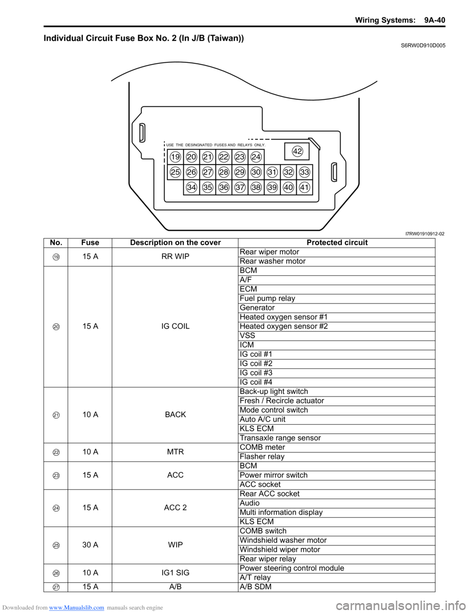
Individual Circuit Fuse Box No. 2 (In J/B (Taiwan))S6RW0D910D005
19
25
20
26
34
21
27
35
22
28
36
23
29
37
24
30
38
31
39
32
40
33
41
42USE THE DESINGNATED FUSES AND RELAYS ONLY.
I7RW01910912-02
No. Fuse Description on the cover Protected circuit
15 A RR WIPRear wiper motor
Rear washer motor
15 A IG COILBCM
A/F
ECM
Fuel pump relay
Generator
Heated oxygen sensor #1
Heated oxygen sensor #2
VSS
ICM
IG coil #1
IG coil #2
IG coil #3
IG coil #4
10 A BACKBack-up light switch
Fresh / Recircle actuator
Mode control switch
Auto A/C unit
KLS ECM
Transaxle range sensor
10 A MTRCOMB meter
Flasher relay
15 A ACCBCM
Power mirror switch
ACC socket
15 A ACC 2Rear ACC socket
Audio
Multi information display
KLS ECM
30 A WIPCOMB switch
Windshield washer motor
Windshield wiper motor
Rear wiper relay
10 A IG1 SIGPower steering control module
A/T relay
15 A A/B A/B SDM
Page 1327 of 1556
Downloaded from www.Manualslib.com manuals search engine Lighting Systems: 9B-8
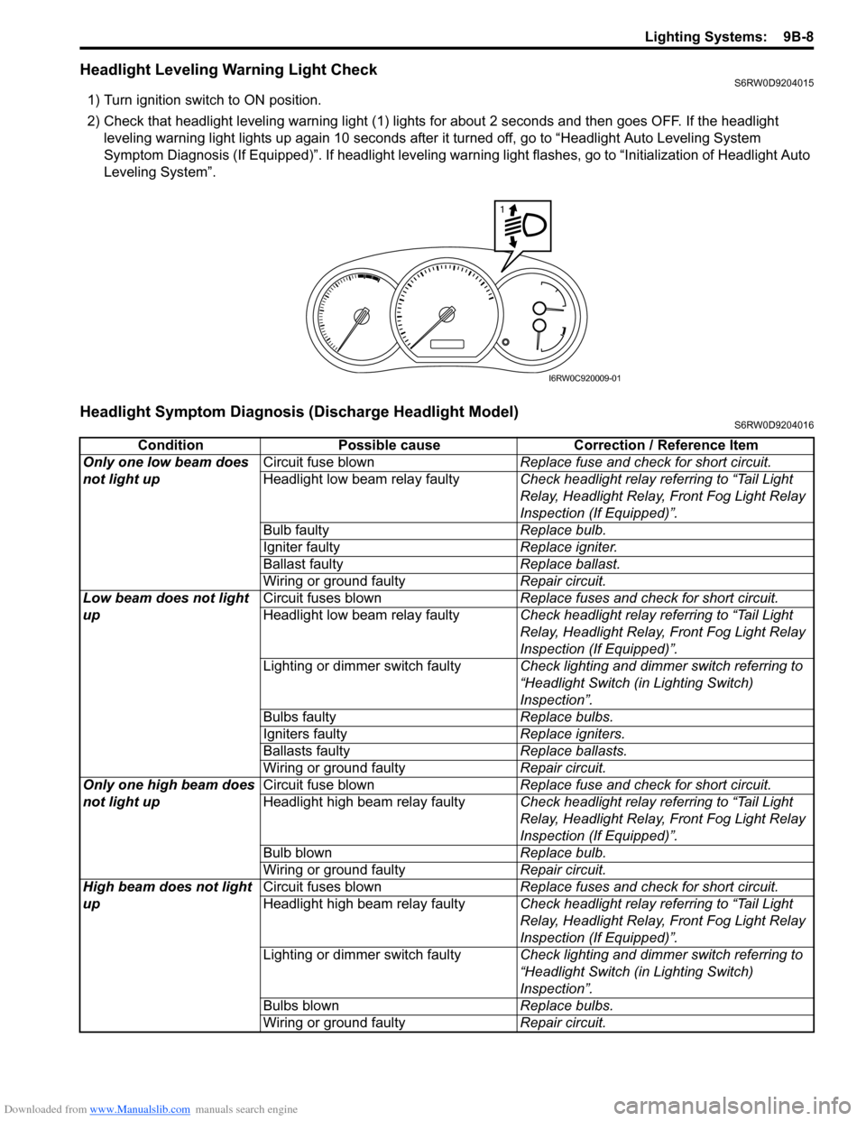
Headlight Leveling Warning Light CheckS6RW0D9204015
1) Turn ignition switch to ON position.
2) Check that headlight leveling warning light (1) lights for about 2 seconds and then goes OFF. If the headlight
leveling warning light lights up again 10 seconds after it turned off, go to “Headlight Auto Leveling System
Symptom Diagnosis (If Equipped)”. If headlight leveling warning light flashes, go to “Initialization of Headlight Auto
Leveling System”.
Headlight Symptom Diagnosis (Discharge Headlight Model)S6RW0D9204016
1
I6RW0C920009-01
Condition Possible cause Correction / Reference Item
Only one low beam does
not light upCircuit fuse blownReplace fuse and check for short circuit.
Headlight low beam relay faultyCheck headlight relay referring to “Tail Light
Relay, Headlight Relay, Front Fog Light Relay
Inspection (If Equipped)”.
Bulb faultyReplace bulb.
Igniter faultyReplace igniter.
Ballast faultyReplace ballast.
Wiring or ground faultyRepair circuit.
Low beam does not light
upCircuit fuses blownReplace fuses and check for short circuit.
Headlight low beam relay faultyCheck headlight relay referring to “Tail Light
Relay, Headlight Relay, Front Fog Light Relay
Inspection (If Equipped)”.
Lighting or dimmer switch faultyCheck lighting and dimmer switch referring to
“Headlight Switch (in Lighting Switch)
Inspection”.
Bulbs faultyReplace bulbs.
Igniters faultyReplace igniters.
Ballasts faultyReplace ballasts.
Wiring or ground faultyRepair circuit.
Only one high beam does
not light upCircuit fuse blownReplace fuse and check for short circuit.
Headlight high beam relay faultyCheck headlight relay referring to “Tail Light
Relay, Headlight Relay, Front Fog Light Relay
Inspection (If Equipped)”.
Bulb blownReplace bulb.
Wiring or ground faultyRepair circuit.
High beam does not light
upCircuit fuses blownReplace fuses and check for short circuit.
Headlight high beam relay faultyCheck headlight relay referring to “Tail Light
Relay, Headlight Relay, Front Fog Light Relay
Inspection (If Equipped)”.
Lighting or dimmer switch faultyCheck lighting and dimmer switch referring to
“Headlight Switch (in Lighting Switch)
Inspection”.
Bulbs blownReplace bulbs.
Wiring or ground faultyRepair circuit.
Page 1328 of 1556

Downloaded from www.Manualslib.com manuals search engine 9B-9 Lighting Systems:
Headlight Symptom diagnosis (Other than Discharge Headlight Model)S6RW0D9204017
Auto-On Headlight System Symptom Diagnosis (If Equipped)S6RW0D9204018
Condition Possible cause Correction / Reference Item
Only one low beam does
not light upCircuit fuse blownReplace fuse and check for short circuit.
Bulb blownReplace bulb.
Headlight low beam relay faulty (if
equipped)Check headlight relay referring to “Tail Light
Relay, Headlight Relay, Front Fog Light Relay
Inspection (If Equipped)”.
Wiring or ground faultyRepair circuit.
Low beam does not light
upCircuit fuse blownReplace fuses and check for short circuit.
Headlight low beam relay faulty (if
equipped)Check headlight relay referring to “Tail Light
Relay, Headlight Relay, Front Fog Light Relay
Inspection (If Equipped)”.
Lighting or dimmer switch faultyCheck lighting and dimmer switch referring to
“Headlight Switch (in Lighting Switch)
Inspection”.
Bulbs blownReplace bulbs.
Wiring or ground faultyRepair circuit.
DRL controller faulty (if equipped)Check system referring to “Inspection of DRL
Controller and Its Circuits (If Equipped)”.
Only one high beam does
not light upCircuit fuse blownReplace fuse and check for short circuit.
Bulb blownReplace bulb.
Headlight high beam relay faulty (if
equipped)Check headlight relay referring to “Tail Light
Relay, Headlight Relay, Front Fog Light Relay
Inspection (If Equipped)”.
Wiring or ground faultyRepair circuit.
High beam does not light
upCircuit fuse blownReplace fuses and check for short circuit.
Headlight high beam relay faulty (if
equipped)Check headlight relay referring to “Tail Light
Relay, Headlight Relay, Front Fog Light Relay
Inspection (If Equipped)”.
Lighting or dimmer switch faultyCheck lighting and dimmer switch referring to
“Headlight Switch (in Lighting Switch)
Inspection”.
Bulbs blownReplace bulbs.
Wiring or ground faultyRepair circuit.
Condition Possible cause Correction / Reference Item
Headlights are not turned
ON or OFF automatically
even after darkened or
lightenedCircuit fuse blownReplace fuse and check for short circuit.
Lighting or dimmer switch faultyCheck lighting and dimmer switch referring to
“Headlight Switch (in Lighting Switch)
Inspection”.
Auto-on headlight sensor faultyCheck auto-on headlight sensor referring to
“Auto-On Headlight Sensor Inspection (If
Equipped)”.
Wiring or ground faultyRepair circuit.
Auto-on headlight controller faultyCheck auto-on headlight controller for function
referring to “Inspection of Auto-On Headlight
Controller and Its Circuit (If Equipped)”.