2006 SUZUKI SX4 Seat heater
[x] Cancel search: Seat heaterPage 1210 of 1556
Downloaded from www.Manualslib.com manuals search engine 9A-43 Wiring Systems:
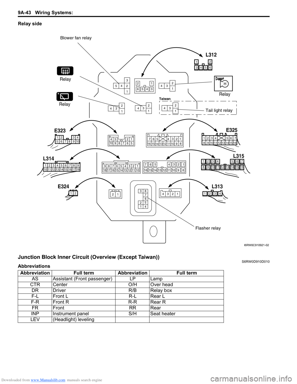
Relay side
Junction Block Inner Circuit (Overview (Except Taiwan))S6RW0D910D010
Abbreviations
543
2
1
432
1432
1432
1
4
32
1
Blower fan relay
Relay
23412 11 2
12 34 5 6 78 9
15 16 17 18 11 10 12 13 144 3561214
11
1015
721
1316
9 8 1
234
5
678 910
4
321
10
987 656
5 4 3
2
17
11 10
9 8
15
14 13
1216
987654321
13 12 11 10 17 18 16 15 14
13
14 15
16
9 10 11
128 5 6
72 3
41
321 4
E323
L314
E324L313L315 E325
HRelay
Relay
Tail light relay
38
7
6
5
2
4 1
43
5
6
12 14 11 10 15 72
1
13 16 9 8
3456
12
L312
6543
21
Flasher relay
Taiwan
I6RW0C910921-02
Abbreviation Full term Abbreviation Full term
AS Assistant (Front passenger) LP Lamp
CTR Center O/H Over head
DR Driver R/B Relay box
F-L Front L R-L Rear L
F-R Front R R-R Rear R
FR Front RR Rear
INP Instrument panel S/H Seat heater
LEV (Headlight) leveling
Page 1217 of 1556
Downloaded from www.Manualslib.com manuals search engine Wiring Systems: 9A-50
Junction Block Inner Circuit (Overview (Taiwan))S6RW0D910D007
Abbreviations
Abbreviation Full term Abbreviation Full term
AS Assistant (Front passenger) LP Lamp
CTR Center O/H Over head
DR Driver R/B Relay box
F-L Front L R-L Rear L
F-R Front R R-R Rear R
FR Front RR Rear
INP Instrument panel S/H Seat heater
LEV (Headlight) leveling
Page 1224 of 1556
Downloaded from www.Manualslib.com manuals search engine 9A-57 Wiring Systems:
System Circuit Diagram
System Circuit DiagramS6RW0D910E001
Refer to “A-1 Cranking System Circuit Diagram”.
Refer to “A-2 Charging System Circuit Diagram”.
Refer to “A-3 Ignition System Circuit Diagram (M15A engine, M16A engine)”.
Refer to “A-3 Ignition System Circuit Diagram (J20A engine)”.
Refer to “A-4 Cooling System Circuit Diagram (M15A engine, M16A engine)”.
Refer to “A-4 Cooling System Circuit Diagram (J20A engine)”.
Refer to “A-5 Engine and A/C Control System Circuit Diagram (M15A engine)”.
Refer to “A-5 Engine and A/C Control System Circuit Diagram (M16A engine)”.
Refer to “A-5 Engine and A/C Control System Circuit Diagram (J20A engine)”.
Refer to “A-6 A/T Control System Circuit Diagram”.
Refer to “A-7 Immobilizer System Circuit Diagram”.
Refer to “A-8 Body Control System Circuit Diagram (Except Taiwan)”.
Refer to “A-8 Body Control System Circuit Diagram (Taiwan)”.
Refer to “A-10 4WD Control System (Except Taiwan)”
Refer to “B-1 Windshield Wiper and Washer Circuit Diagram”.
Refer to “B-2 Rear Wiper and Washer Circuit Diagram (Except Taiwan)”.
Refer to “B-2 Rear Wiper and Washer Circuit Diagram (Taiwan)”.
Refer to “B-3 Rear Defogger Circuit Diagram (Except Taiwan)”.
Refer to “B-3 Rear Defogger Circuit Diagram (Taiwan)”.
Refer to “B-4 Power Window Circuit Diagram”.
Refer to “B-5 Power Door Lock Circuit Diagram (Except Taiwan)”.
Refer to “B-5 Power Door Lock Circuit Diagram (Taiwan)”.
Refer to “B-6 Power Mirror Circuit Diagram (Except Taiwan)”.
Refer to “B-6 Power Mirror Circuit Diagram (Taiwan)”.
Refer to “B-7 Horn Circuit Diagram”.
Refer to “B-8 Seat Heater Circuit Diagram”.
Refer to “B-9 Keyless Start System Circuit Diagram”
Refer to “C-1 Combination Meter Circuit Diagram (Meter)”.
Refer to “C-2 Combination Meter Circuit Diagram (Indicator)”.
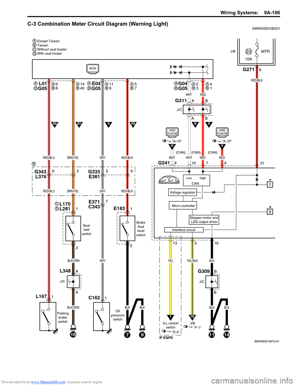
Refer to “C-3 Combination Meter Circuit Diagram (Warning Light)”.
Refer to “D-1 Headlight System Circuit Diagram (Except Taiwan)”.
Refer to “D-1 Headlight System Circuit Diagram (Taiwan)”.
Refer to “D-2 Position, Tail and Licence Plate Light System Circuit Diagram (Except Taiwan)”.
Refer to “D-2 Position, Tail and Licence Plate Light System Circuit Diagram (Taiwan)”.
Refer to “D-3 Front Fog Light System Circuit Diagram (Except Taiwan)”.
Refer to “D-3 Front Fog Light System Circuit Diagram (Taiwan)”.
Refer to “D-4 Illumination Light System Circuit Diagram (Except Taiwan)”.
Refer to “D-4 Illumination Light System Circuit Diagram (Taiwan)”.
Refer to “D-5 Interior Light System Circuit Diagram (Except Taiwan)”.
Refer to “D-5 Interior Light System Circuit Diagram (Taiwan)”.
Refer to “D-6 Turn Signal and Hazard Warning Light System Circuit Diagram (Except Taiwan)”.
Refer to “D-6 Turn Signal and Hazard Warning Light System Circuit Diagram (Taiwan)”.
Refer to “D-7 Brake Light System Circuit Diagram”.
Refer to “D-8 Back-Up Light System Circuit Diagram”.
Refer to “D-9 Headlight Beam Leveling System Circuit Diagram (Manual Leveling)”.
Refer to “D-10 Rear Fog Light Circuit Diagram”.
Refer to “E-1 Heater System Circuit Diagram”.
Refer to “E-2 Auto A/C System Circuit Diagram”.
Refer to “F-1 Air-Bag System Circuit Diagram (4ch)”.
Refer to “F-1 Air-Bag System Circuit Diagram (8ch)”.
Refer to “F-2 Anti-Lock Brake System Circuit Diagram”.
Refer to “F-4 Power Steering System Circuit Diagram”.
Refer to “G-1 Audio System Circuit Diagram”.
Refer to “G-2 Multi Information Display / Accessory Socket System Circuit Diagram”.
Refer to “G-4 Navigation System Circuit Diagram”.
Page 1269 of 1556
Downloaded from www.Manualslib.com manuals search engine Wiring Systems: 9A-102
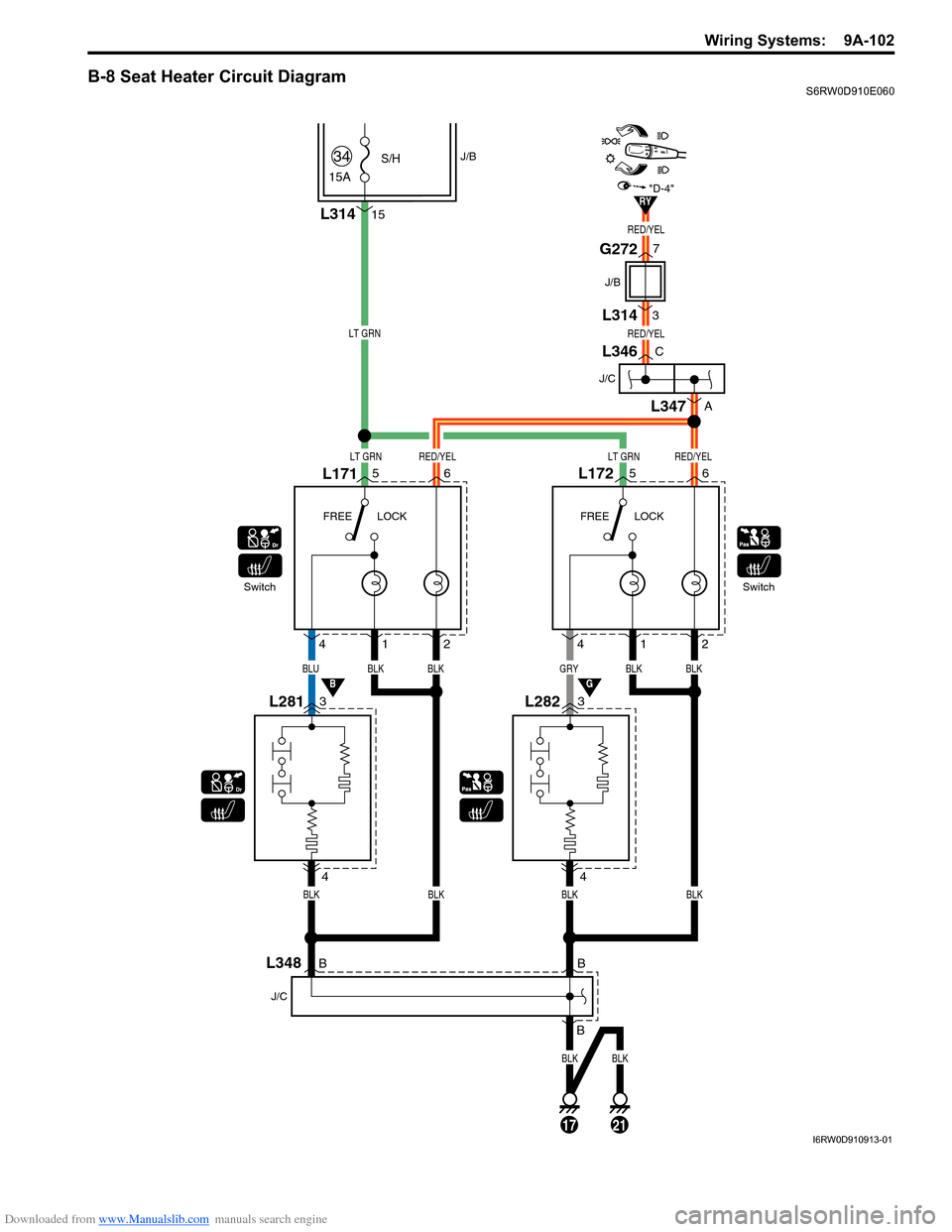
B-8 Seat Heater Circuit DiagramS6RW0D910E060
LT GRN
LT GRNLT GRNRED/YEL
RED/YEL
RED/YEL
RED/YEL
BLUBLK
L17156
L2813 4
4
12
L1725
L2823
4
BLKGRYBLK
412
BLK
BLKBLKBLKBLK
SwitchFREE LOCK FREE LOCKSwitch
L31415
15A
S/H34J/B
6
J/C
L346C
A
L347
RY
BG
"D-4"
7
3
J/B
G272
L314
B
BLK
B
B
J/C
L348
17
BLK
21I6RW0D910913-01
Page 1273 of 1556
Downloaded from www.Manualslib.com manuals search engine Wiring Systems: 9A-106
C-3 Combination Meter Circuit Diagram (Warning Light)S6RW0D910E021
J/BMTR
10A22
31
Stepper motor and
LED output driver
Voltage regulator
Micro controller
G2716
RED/BLK
516
YB
YEL/BLK
"F-1"
CAN
High Low
WHTWHTRED
RW
10G2419
7
L01
G05
RED/BLUBRN/YEL
L1671
Parking
brake
switch
1
2
A
A
16
BLK/ORN
BLK/ORN
J/C
L348B
B
J/C
G309
Seat
belt
switch
Oil
pressure
switch
J/B
13
Y
YEL
"D-4"
ILL cancel
switch
E371
C3437
G343
L37693G333
E38156
GRY
GRY
1C162
RED/BLK
RED/BLUBRN/YELGRYRED/BLK
E1831
Brake
fluid
level
switch
2
71114
BLK
BLK
BLK
9
BLKBLK
W
WHTRED
1
2
A
AB
B
J/C
G311
RBGBYRB
BCM
"A-10"
4WD
Cont.M
Interface circuit
RED
6
R"A-10"
4WD
Cont.M
(CAN) (CAN) (CAN)
IF EQPD
Except Taiwan
Taiwan
Without seat heater
With seat heater A
A
B
L170
L281C
D
G04
G05A
BE04
G05A
B
BCD
B
6
8AB14
40AB11
9AB5
7AB2
3AB4
1AB
I6RW0D910915-01
Page 1428 of 1556
Downloaded from www.Manualslib.com manuals search engine 9G-1 Seats:
Body, Cab and Accessories
Seats
Diagnostic Information and Procedures
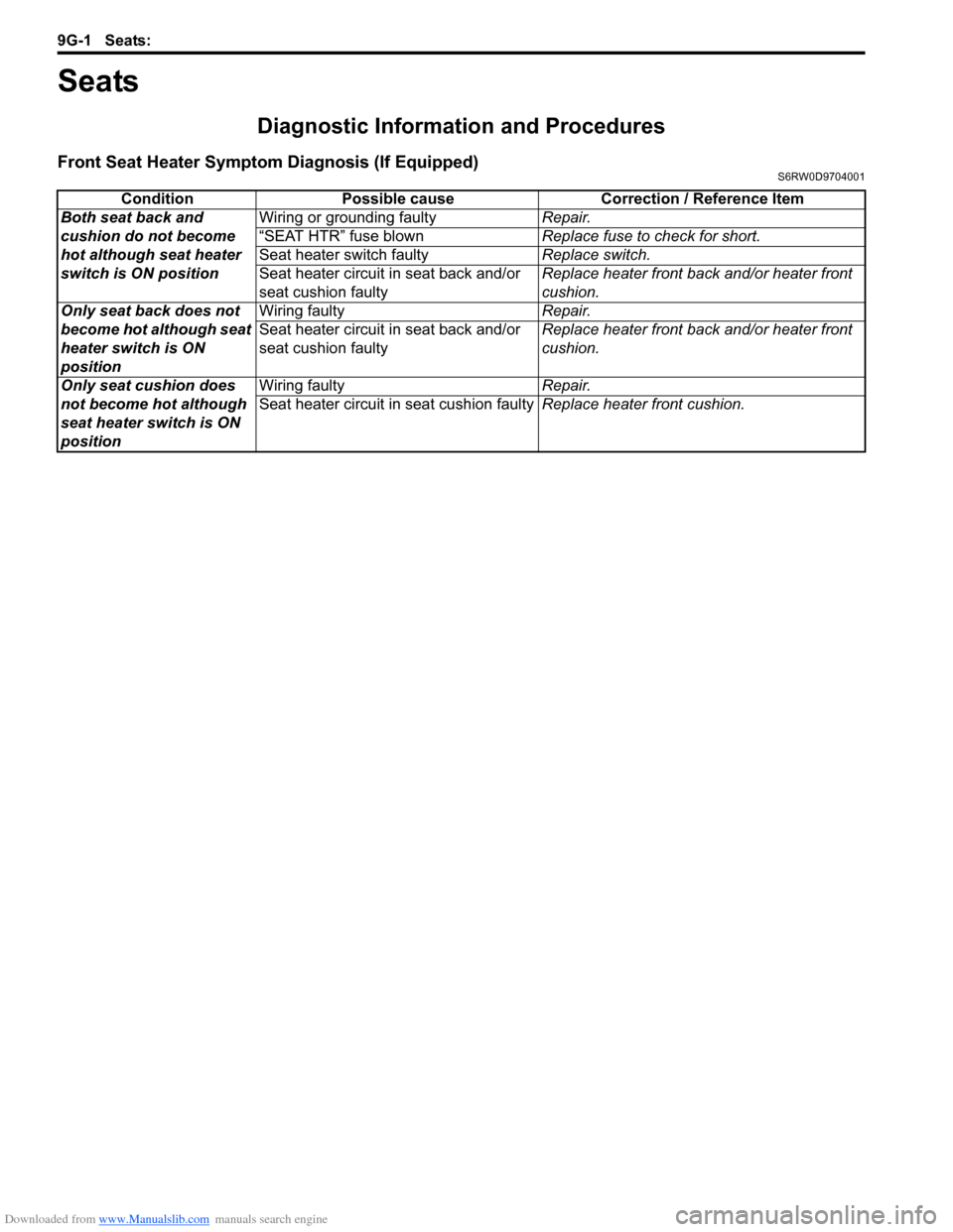
Front Seat Heater Symptom Diagnosis (If Equipped)S6RW0D9704001
Condition Possible cause Correction / Reference Item
Both seat back and
cushion do not become
hot although seat heater
switch is ON positionWiring or grounding faultyRepair.
“SEAT HTR” fuse blownReplace fuse to check for short.
Seat heater switch faultyReplace switch.
Seat heater circuit in seat back and/or
seat cushion faultyReplace heater front back and/or heater front
cushion.
Only seat back does not
become hot although seat
heater switch is ON
positionWiring faultyRepair.
Seat heater circuit in seat back and/or
seat cushion faultyReplace heater front back and/or heater front
cushion.
Only seat cushion does
not become hot although
seat heater switch is ON
positionWiring faultyRepair.
Seat heater circuit in seat cushion faultyReplace heater front cushion.
Page 1430 of 1556
Downloaded from www.Manualslib.com manuals search engine 9G-3 Seats:
Front Seat Removal and InstallationS6RW0D9706002
Removal
1) Disable air bag system referring to “Disabling Air
Bag System in Section 8B”.
2) Disconnect seat harness coupler and side air bag
coupler, if equipped.
3) Remove 4 mounting bolts to remove seat assembly.
4) Disassemble and repair seat as necessary.
Installation
Reverse removal procedure to install front seat.
• Torque to specifications as shown in “Front Seat
Components”.
• Enable air bag system referring to “Enabling Air Bag
System in Section 8B”.
Front Seat Heater Switch (Driver and Passenger
Side) Inspection (If Equipped)
S6RW0D9706005
1) Confirm that ignition switch is OFF position.
2) Remove console box.
3) Disconnect seat heater switch coupler and remove
seat heater switch.
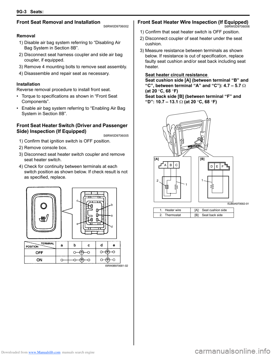
4) Check for continuity between terminals at each
switch position as shown below. If check result is not
as specified, replace.
Front Seat Heater Wire Inspection (If Equipped)S6RW0D9706006
1) Confirm that seat heater switch is OFF position.
2) Disconnect coupler of seat heater under the seat
cushion.
3) Measure resistance between terminals as shown
below. If resistance is out of specification, replace
faulty seat cushion and/or seat back including seat
heater.
Seat heater circuit resistance
Seat cushion side [A] (between terminal “B” and
“C”, between terminal “A” and “C”): 4.7 – 5.7 Ω
(at 20 °C, 68 °F)
Seat back side [B] (between terminal “F” and
“D”: 10.7 – 13.1 Ω (at 20 °C, 68 °F)
I5RW0B970001-02
1. Heater wire [A]: Seat cushion side
2. Thermostat [B]: Seat back side
ABCDE F [A] [B]
11
2
I5JB0A970002-01
Page 1474 of 1556
Downloaded from www.Manualslib.com manuals search engine 10B-1 Body Electrical Control System:
Control Systems
Body Electrical Control System
Precautions
Precautions in Diagnosing TroubleS6RW0DA200001
• Diagnostic information stored in BCM memory can be cleared as well as checked by using SUZUKI scan tool.
Before using scan tool, read its Operator’s (Instruction) Manual carefully to have good understanding as to what
functions are available and how to use it.
• Be sure to read “Precautions for Electrical Circuit Service in Section 00” before inspection and observe what is
written there.
• Communication of ECM, TCM (A/T model), ABS control module, 4WD control module (if equipped), keyless start
control module (if equipped), combination meter and BCM is established by CAN (Controller Area Network). For
detail of CAN communication for BCM, refer to “CAN Communication System Description”. Therefore, handle CAN
communication line with care referring to “Precaution for CAN Communication System in Section 00”.
General Description
BCM General DescriptionS6RW0DA201001
The Body electrical Control Module (BCM) is
incorporated in junction block. Do not attempt removal of
BCM from junction block as it may cause contact failure.
The BCM incorporates relays and controllers which are
used for the following systems and controls them.
• Power door lock (if equipped)
• Keyless entry (if equipped)
• Door lock function of keyless start system (if
equipped)
• Rear wiper
• Combination meter
• Interior light• Warning buzzer
• Rear end door window defogger and door mirror
heater (if equipped)
• Rear end door opener (if equipped)
• Theft deterrent light
Also, the BCM has a function to cause the interior light
and open door warning light in the combination meter to
turn off when any door is left open for longer than 15
minutes to reduce wasteful battery consumption.
In addition, it is possible to check operation of actuator
which is controlled by BCM by using the output test
function of SUZUKI scan tool to operate actuator
simulatively.
CAN Communication System DescriptionS6RW0DA201002
Refer to “CAN Communication System Description in Section 1A” for CAN communication system description.
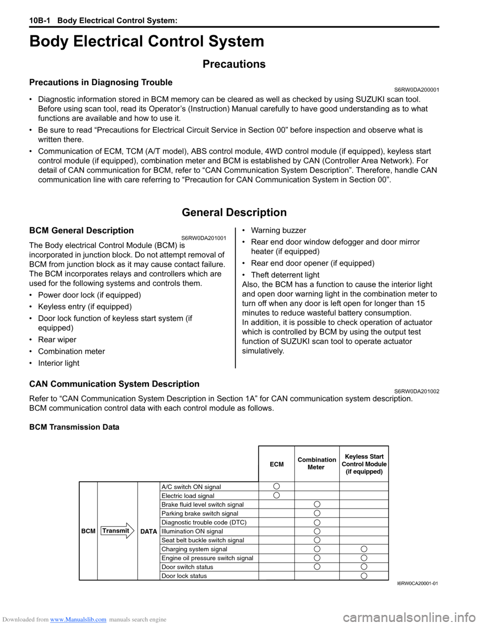
BCM communication control data with each control module as follows.
BCM Transmission Data
A/C switch ON signal
Electric load signal
Brake fluid level switch signal
Parking brake switch signal
Diagnostic trouble code (DTC)
Illumination ON signal
Seat belt buckle switch signal
Charging system signal
Engine oil pressure switch signal
Door switch status
Door lock statusECMKeyless Start
Control Module
(if equipped) Combination
Meter
BCMTransmit
DATA
I6RW0CA20001-01