2006 SUZUKI SX4 Power door
[x] Cancel search: Power doorPage 1171 of 1556
![SUZUKI SX4 2006 1.G Service Workshop Manual Downloaded from www.Manualslib.com manuals search engine Wiring Systems: 9A-4
How to Read Connector Layout DiagramS6RW0D9101004
[A-1]: Harness symbol and corresponding harness name
A: Battery harness SUZUKI SX4 2006 1.G Service Workshop Manual Downloaded from www.Manualslib.com manuals search engine Wiring Systems: 9A-4
How to Read Connector Layout DiagramS6RW0D9101004
[A-1]: Harness symbol and corresponding harness name
A: Battery harness](/manual-img/20/7612/w960_7612-1170.png)
Downloaded from www.Manualslib.com manuals search engine Wiring Systems: 9A-4
How to Read Connector Layout DiagramS6RW0D9101004
[A-1]: Harness symbol and corresponding harness name
A: Battery harness
B: A/C harness
C: Engine harness
D: Injector harness
E: Main harness, Oil pressure switch wire, Console wire
G: Instrument panel harness
J: Side door wire (Power window)
K: Interior light harness, Rear speaker wire, Roof wire
L: Floor harness, G sensor wire (Fuel pump harness)
M: Rear bumper harness
O: Rear end door harness
Q: Air bag/Pretensioner harness
R: (Fuel pump wire)
[A-2]: Connector Number
[B]: Ground point No.
12
11
[B][B]
Connector code
[A-1] [A-2]L 36
L13L15
R01 L14L12L11L10 L09 L36
R02 L24 L25 L33
L28 L20 L26 (TO O01)
{
L05
L16
L32 L19 L01 (TO G01)
L02 (TO E04)
L03 (TO E05) L42
R05 R04
L07 (TO K02)
I2RH01910901-01
Page 1192 of 1556
Downloaded from www.Manualslib.com manuals search engine 9A-25 Wiring Systems:
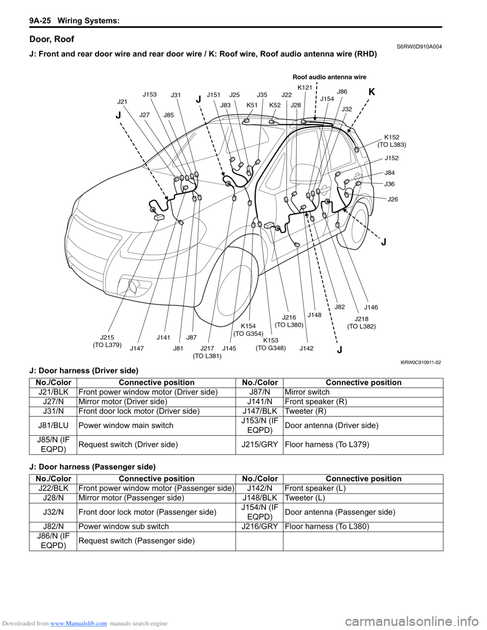
Door, RoofS6RW0D910A004
J: Front and rear door wire and rear door wire / K: Roof wire, Roof audio antenna wire (RHD)
J: Door harness (Driver side)
J: Door harness (Passenger side)
J21J153J31
J83
J35
K51J28J154 K121
J32
K152
(TO L383)
J27J85
J151J25
K52
J22
J148
J86
J152
J215
(TO L379)J141
J147J81
J87K153
(TO G348)
K154
(TO G354)
J145J142J82
J146
J218
(TO L382)
J217
(TO L381)
J216
(TO L380)J84
J36
J26
J
J JK
J
Roof audio antenna wire
I6RW0C910911-02
No./Color Connective position No./Color Connective position
J21/BLK Front power window motor (Driver side) J87/N Mirror switch
J27/N Mirror motor (Driver side) J141/N Front speaker (R)
J31/N Front door lock motor (Driver side) J147/BLK Tweeter (R)
J81/BLU Power window main switchJ153/N (IF
EQPD)Door antenna (Driver side)
J85/N (IF
EQPD)Request switch (Driver side) J215/GRY Floor harness (To L379)
No./Color Connective position No./Color Connective position
J22/BLK Front power window motor (Passenger side) J142/N Front speaker (L)
J28/N Mirror motor (Passenger side) J148/BLK Tweeter (L)
J32/N Front door lock motor (Passenger side)J154/N (IF
EQPD)Door antenna (Passenger side)
J82/N Power window sub switch J216/GRY Floor harness (To L380)
J86/N (IF
EQPD)Request switch (Passenger side)
Page 1193 of 1556
Downloaded from www.Manualslib.com manuals search engine Wiring Systems: 9A-26
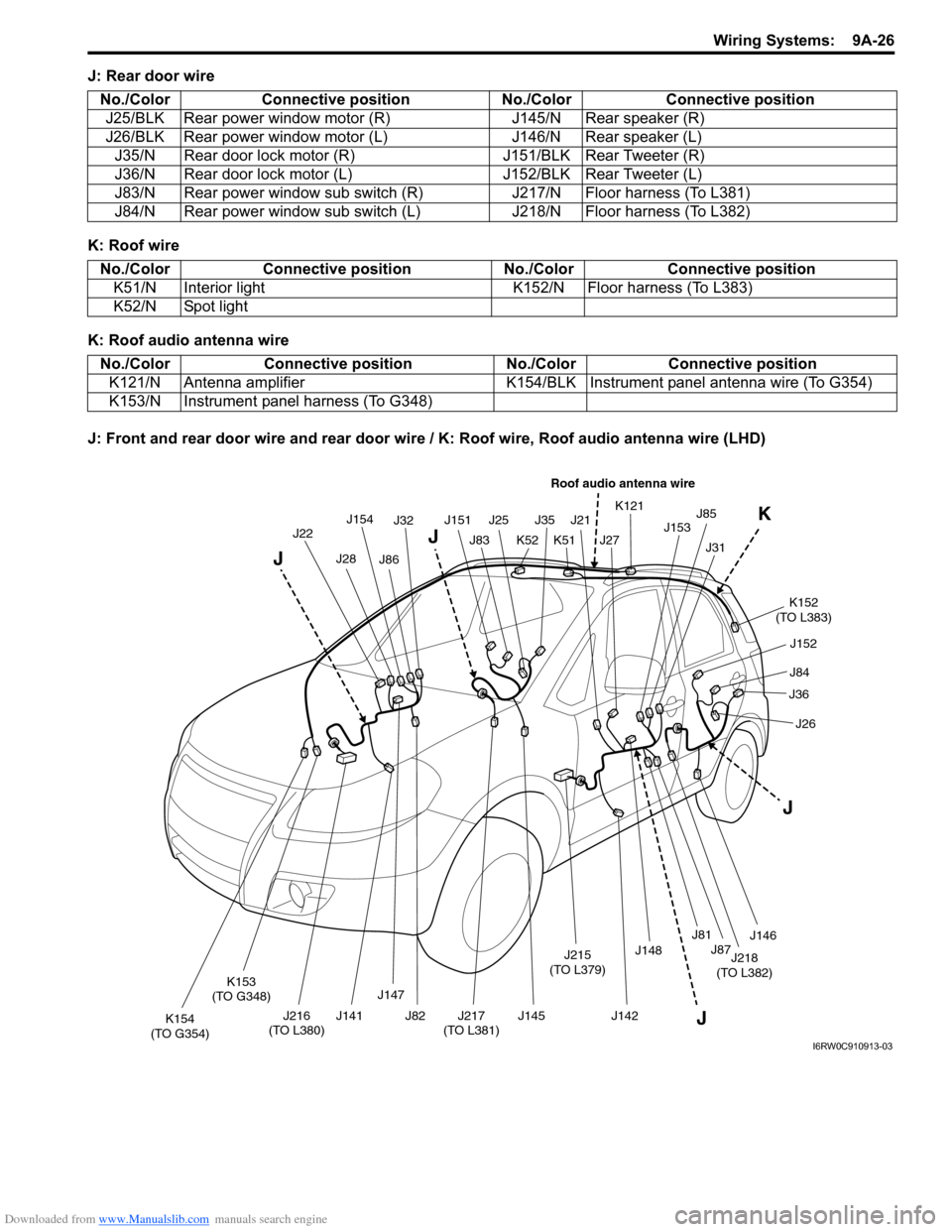
J: Rear door wire
K: Roof wire
K: Roof audio antenna wire
J: Front and rear door wire and rear door wire / K: Roof wire, Roof audio antenna wire (LHD)No./Color Connective position No./Color Connective position
J25/BLK Rear power window motor (R) J145/N Rear speaker (R)
J26/BLK Rear power window motor (L) J146/N Rear speaker (L)
J35/N Rear door lock motor (R) J151/BLK Rear Tweeter (R)
J36/N Rear door lock motor (L) J152/BLK Rear Tweeter (L)
J83/N Rear power window sub switch (R) J217/N Floor harness (To L381)
J84/N Rear power window sub switch (L) J218/N Floor harness (To L382)
No./Color Connective position No./Color Connective position
K51/N Interior light K152/N Floor harness (To L383)
K52/N Spot light
No./Color Connective position No./Color Connective position
K121/N Antenna amplifier K154/BLK Instrument panel antenna wire (To G354)
K153/N Instrument panel harness (To G348)
J22J154J32
J83
J35
K51J27J153 K121
J31
K152
(TO L383)
J28J86
J151J25
K52
J21
J148
J85
J152
J216
(TO L380)J141
J147
J82
J87
K153
(TO G348)
K154
(TO G354)J145J142J81
J146
J218
(TO L382)
J217
(TO L381)
J215
(TO L379)J84
J36
J26
J
J JK
J
Roof audio antenna wire
I6RW0C910913-03
Page 1194 of 1556
Downloaded from www.Manualslib.com manuals search engine 9A-27 Wiring Systems:
J: Door harness (Driver side)
J: Door harness (Passenger side)
J: Rear door wire
K: Roof wire
K: Roof audio antenna wireNo./Color Connective position No./Color Connective position
J21/BLK Front power window motor (Driver side) J87/N Mirror switch
J27/N Mirror motor (Driver side) J142/N Front speaker (L)
J31/N Front door lock motor (Driver side) J148/BLK Tweeter (L)
J81/BLU Power window main switchJ153/N (IF
EQPD)Door antenna (Driver side)
J85/N (IF
EQPD)Request switch (Driver side) J215/GRY Floor harness (To L379)
No./Color Connective position No./Color Connective position
J22/BLK Front power window motor (Passenger side) J141/N Front speaker (R)
J28/N Mirror motor (Passenger side) J147/BLK Tweeter (R)
J32/N Front door lock motor (Passenger side)J154/N (IF
EQPD)Door antenna (Passenger side)
J82/N Power window sub switch J216/GRY Floor harness (To L380)
J86/N (IF
EQPD)Request switch (Passenger side)
No./Color Connective position No./Color Connective position
J25/BLK Rear power window motor (R) J145/N Rear speaker (R)
J26/BLK Rear power window motor (L) J146/N Rear speaker (L)
J35/N Rear door lock motor (R) J151/BLK Rear Tweeter (R)
J36/N Rear door lock motor (L) J152/BLK Rear Tweeter (L)
J83/N Rear power window sub switch (R) J217/N Floor harness (To L381)
J84/N Rear power window sub switch (L) J218/N Floor harness (To L382)
No./Color Connective position No./Color Connective position
K51/N Interior light K152/N Floor harness (To L383)
K52/N Spot light
No./Color Connective position No./Color Connective position
K121/N Antenna amplifier K154/BLK Instrument panel antenna wire (To G354)
K153/N Instrument panel harness (To G348)
Page 1211 of 1556
Downloaded from www.Manualslib.com manuals search engine Wiring Systems: 9A-44
1IG2 SW2
6
LAMP FL
1A/B CONT
A/B SIGNAL
K-LINE
K-LINE
A/B SIGNAL
BCM IG1
D/SL-IN
D/L-IN
D/UL-1
SEQULITY IN
HAZARD
TAIL BCM
D/L (BCM)
RR DEF RLY
BCM (+B)
DOME LP CONT
ACC
R/WIP
GND
SIGNAL GND (BCM)4A/B IND
32
98
2511
2423
206
1412
181
215
107
2217
3
1IG
3LP-L2LP-R
4+B5SW-L
7GND6SW-R
8HAZ
DOME LP (+B)543GND SPARE-1 DOME LP DOOR6HTR4ST1IG25ACC3IG SW (+B)2IG1
18107G271415G2727G27219G2721G27212G2719G27111G2723G2722G2728G272166G2716G2725G271810511G27113G2724G2721G27120G2722G2719G2723G27112G27214G272
10E3235E32512E3259E32514E3251E3258E3252E32511E3253E3256E3235E32316E3257E3254E3232E3239E3233E3237E32310E325 DEF IND RR FOG(+B)
*
*
TAIL(+B)
TAIL SW
TURN SW-L
TURN SW-R
METER (L)
METER (R)
HAZARD SW
HORN SW
H/L LVL SW
*
*
MTR (IG) ANGLE SENSOR
IG COIL
DOME +B
4WD CONT
ACC 2
A/B INDACC 1
F-WIP (RLY)
R-WASHER
*
*
* *
*GND (IP)
SIGNAL GND (IP)
*
*
*
IG COIL
EPS AT
ABS CONT
BACK
STOP SW
EPI
BUL IN
HORN
FR TURN (R)
FR TURN (L)
POSI LP
* *
EPI
STOP SW
F-WIP
HTR FUSE
ST RLY COIL
4
L314
15
L314
16
L314
5
L314
9
L314
212
L314
13
L315
14
L315
7
L315
15
L315
14
L314
11
L314
6
L315
5
L315
8
L314
7
L314
6
L314
18
L314
3
L314
L314
110
L314
9
L315
10
L315
1
L315
3
L315
2
L315
8
L315
11
L315
4
L315 SIGNAL GND (FL)
SEAT HTR
P/W
R-WIP (-)* *ACC 2
ACC 1*
*
DOME (+B)
* * *
*
RR DEF
HTR MIR (L)
HTR MIR (R)
TAIL LP, LICENSEPOWER DR
RR-TURN (L)
RR-TURN (R)
BUL-LD/L-1
D/SL-1 D/UL-1
STOP LP
IG1 ABS
*
*
IG COIL 15A
MTR 10A
A/B 15A
IG1 SIG 10A
ABS 10A
BACK 10A
TAIL 10A
D/L 20A
P/WT 20A
RR DEF 30A
RR FOG 15A
SPARE-2
ACC 15A
ACC 2 15A
WIP 30A
P/W 30A
RR WIP 15A
S/H 15A
IG2 SIG 10A
ST SIG 10A HORN HAZ 15A
STOP 15A4WD 15ARR DEF RLY
SPARE-3
HORN RLY
RR WIP RLY
G272 G272
G271
G272
G271
G272 G271
L314
DOME 15A
To instrument panel harness
(G273)*: Not used To floor harness
(L312)
To instrument panel
harness
(G271 , G272)
To main harness
(E323 , E325)
To floor harness (L314 , L315)To main
harness
(E324)
BCM
To flasher
relayTo floor
harness
(L313)
BLOWER FAN RLY
I6RW0D910904-03
Page 1216 of 1556
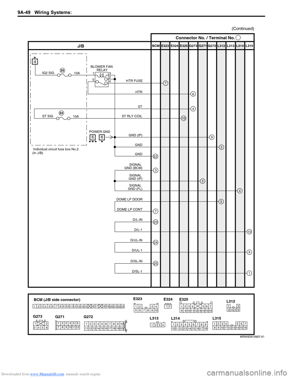
Downloaded from www.Manualslib.com manuals search engine 9A-49 Wiring Systems:
BCM (J/B side connector)
3
4
1
25
15 14 12
13 10
11 9 8 67
17
16182122 19
20
23
1234578 116
12 91034 652 1
G271 G273
G272
10
11 12 13 14 15 16 17 18 19123456789
20
345612L312
23414
3
561214 11
10
157 2 11316 9 8 6
5 4 3
2
1
7
11 10
9 8
15
14 13
1216
L313
L315 E325
2 1
12 34 5 6 78 9
15 16 17 18 11 10 12 13 14 1
234
5
678 910
E323
L314 E324
E323 E325E324 BCM G272G271 G273 L312 L313 L314 L315J/B
9
3
3
4
(Continued)
GND (IP) POWER GND
GND
22GND
SIGNAL
GND (FL)SIGNAL
GND (IP)
5
7DOME LP CONT DOME LP DOOR
23
10D/L-1 D/L-IN
25
1D/SL-1 D/SL-IN
24
9D/UL-1 D/UL-IN
3
SIGNAL
GND (BCM)
4
4
10
ST
ST RLY COIL
ST SIG
10A33
Individual circuit fuse box No.2
(In J/B)
7
6
BLOWER FAN
RELAY
HTR HTR FUSE
IG2 SIG
10A35
3 1
5
4
2
Connector No. / Terminal No.
56
I6RW0D910907-01
Page 1224 of 1556
Downloaded from www.Manualslib.com manuals search engine 9A-57 Wiring Systems:
System Circuit Diagram
System Circuit DiagramS6RW0D910E001
Refer to “A-1 Cranking System Circuit Diagram”.
Refer to “A-2 Charging System Circuit Diagram”.
Refer to “A-3 Ignition System Circuit Diagram (M15A engine, M16A engine)”.
Refer to “A-3 Ignition System Circuit Diagram (J20A engine)”.
Refer to “A-4 Cooling System Circuit Diagram (M15A engine, M16A engine)”.
Refer to “A-4 Cooling System Circuit Diagram (J20A engine)”.
Refer to “A-5 Engine and A/C Control System Circuit Diagram (M15A engine)”.
Refer to “A-5 Engine and A/C Control System Circuit Diagram (M16A engine)”.
Refer to “A-5 Engine and A/C Control System Circuit Diagram (J20A engine)”.
Refer to “A-6 A/T Control System Circuit Diagram”.
Refer to “A-7 Immobilizer System Circuit Diagram”.
Refer to “A-8 Body Control System Circuit Diagram (Except Taiwan)”.
Refer to “A-8 Body Control System Circuit Diagram (Taiwan)”.
Refer to “A-10 4WD Control System (Except Taiwan)”
Refer to “B-1 Windshield Wiper and Washer Circuit Diagram”.
Refer to “B-2 Rear Wiper and Washer Circuit Diagram (Except Taiwan)”.
Refer to “B-2 Rear Wiper and Washer Circuit Diagram (Taiwan)”.
Refer to “B-3 Rear Defogger Circuit Diagram (Except Taiwan)”.
Refer to “B-3 Rear Defogger Circuit Diagram (Taiwan)”.
Refer to “B-4 Power Window Circuit Diagram”.
Refer to “B-5 Power Door Lock Circuit Diagram (Except Taiwan)”.
Refer to “B-5 Power Door Lock Circuit Diagram (Taiwan)”.
Refer to “B-6 Power Mirror Circuit Diagram (Except Taiwan)”.
Refer to “B-6 Power Mirror Circuit Diagram (Taiwan)”.
Refer to “B-7 Horn Circuit Diagram”.
Refer to “B-8 Seat Heater Circuit Diagram”.
Refer to “B-9 Keyless Start System Circuit Diagram”
Refer to “C-1 Combination Meter Circuit Diagram (Meter)”.
Refer to “C-2 Combination Meter Circuit Diagram (Indicator)”.
Refer to “C-3 Combination Meter Circuit Diagram (Warning Light)”.
Refer to “D-1 Headlight System Circuit Diagram (Except Taiwan)”.
Refer to “D-1 Headlight System Circuit Diagram (Taiwan)”.
Refer to “D-2 Position, Tail and Licence Plate Light System Circuit Diagram (Except Taiwan)”.
Refer to “D-2 Position, Tail and Licence Plate Light System Circuit Diagram (Taiwan)”.
Refer to “D-3 Front Fog Light System Circuit Diagram (Except Taiwan)”.
Refer to “D-3 Front Fog Light System Circuit Diagram (Taiwan)”.
Refer to “D-4 Illumination Light System Circuit Diagram (Except Taiwan)”.
Refer to “D-4 Illumination Light System Circuit Diagram (Taiwan)”.
Refer to “D-5 Interior Light System Circuit Diagram (Except Taiwan)”.
Refer to “D-5 Interior Light System Circuit Diagram (Taiwan)”.
Refer to “D-6 Turn Signal and Hazard Warning Light System Circuit Diagram (Except Taiwan)”.
Refer to “D-6 Turn Signal and Hazard Warning Light System Circuit Diagram (Taiwan)”.
Refer to “D-7 Brake Light System Circuit Diagram”.
Refer to “D-8 Back-Up Light System Circuit Diagram”.
Refer to “D-9 Headlight Beam Leveling System Circuit Diagram (Manual Leveling)”.
Refer to “D-10 Rear Fog Light Circuit Diagram”.
Refer to “E-1 Heater System Circuit Diagram”.
Refer to “E-2 Auto A/C System Circuit Diagram”.
Refer to “F-1 Air-Bag System Circuit Diagram (4ch)”.
Refer to “F-1 Air-Bag System Circuit Diagram (8ch)”.
Refer to “F-2 Anti-Lock Brake System Circuit Diagram”.
Refer to “F-4 Power Steering System Circuit Diagram”.
Refer to “G-1 Audio System Circuit Diagram”.
Refer to “G-2 Multi Information Display / Accessory Socket System Circuit Diagram”.
Refer to “G-4 Navigation System Circuit Diagram”.
Page 1262 of 1556
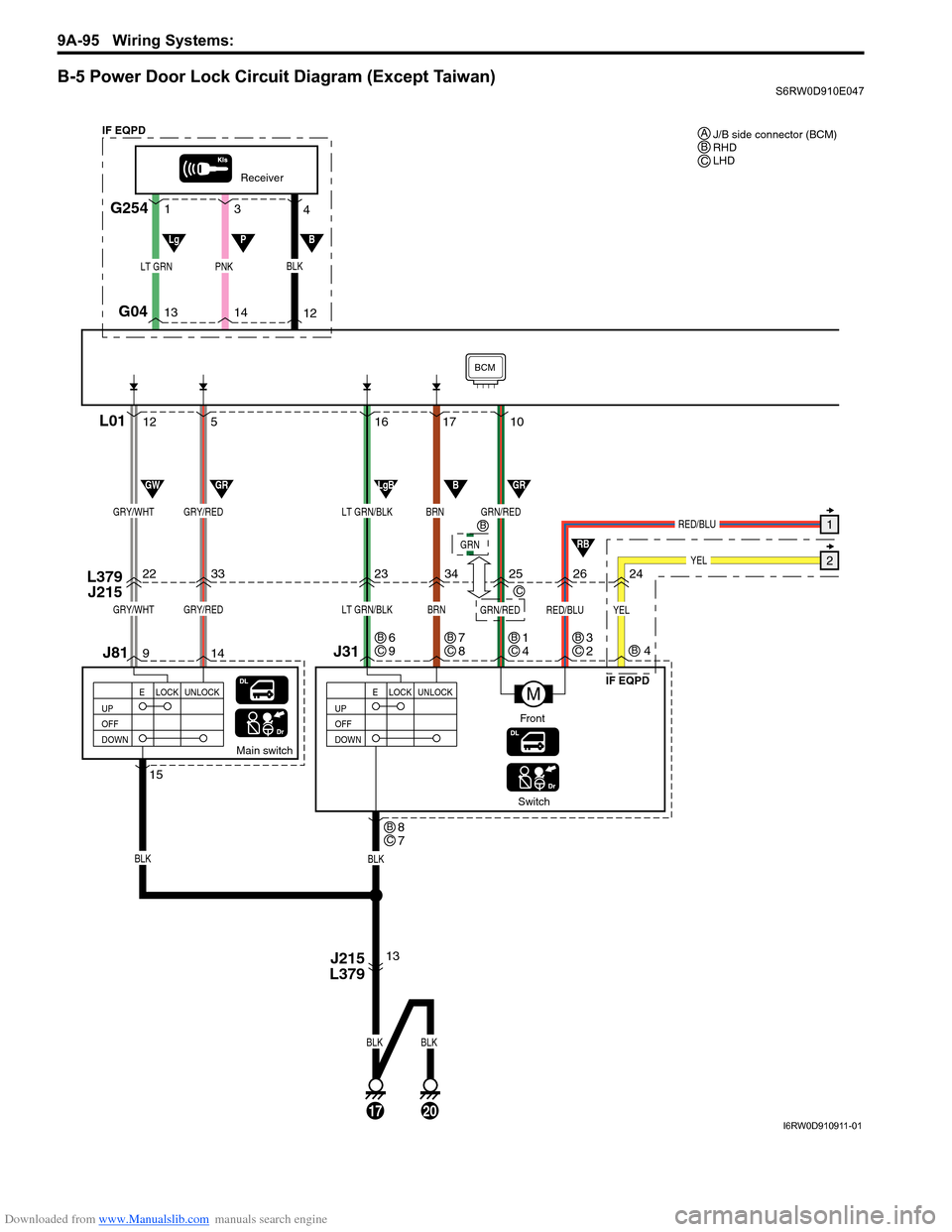
Downloaded from www.Manualslib.com manuals search engine 9A-95 Wiring Systems:
B-5 Power Door Lock Circuit Diagram (Except Taiwan)S6RW0D910E047
17 16
23
34
Switch
J31 L379
J215
BLK
Main switch
13 14 95 12
22
33
J81
BLK
BLK
BRNLT GRN/BLKGRY/REDGRY/WHT
17
BLK
20
UP
OFF
DOWNLOCK UNLOCK
E
Receiver
G254
G04
L01
LT GRNPNK
14 13
12 3 1
4
UP
OFF
DOWNLOCK UNLOCK
E
J215
L379
15
M
BRNLT GRN/BLKGRY/REDGRY/WHTGRN/RED
GRN/RED
BCM
RED/BLU
RED/BLU1
YEL22526
10
LgBBGRGWGR
RB
LgPB
Front
BLK
IF EQPD
IF EQPDJ/B side connector (BCM)
RHD
LHD A
BC
8
7BC
6
9BC7
8BC1
4B
C
GRN
B
C3
2BC
YEL
24
4B
I6RW0D910911-01