2006 SUZUKI SX4 Head light
[x] Cancel search: Head lightPage 287 of 1556

Downloaded from www.Manualslib.com manuals search engine Engine Mechanical: 1D-5
Targeted Timing Varying Operation
Diagnostic Information and Procedures
Compression CheckS6RW0D1404001
Check compression pressure on all 4 cylinders as
follows:
1) Warm up engine to normal operating temperature.
2) Stop engine after warming up.
NOTE
After warming up engine, place transmission
gear shift lever in “Neutral” (shift selector
lever to “P” range for A/T model), and set
parking brake and block drive wheels.
3) Remove air cleaner assembly with air suction hose
referring to “Air Cleaner Assembly Removal and
Installation”.
4) Remove cylinder head upper cover.
5) Remove ignition coil assemblies and all spark plugs
referring to “Spark Plug Removal and Installation in
Section 1H”.
6) Disconnect fuel injector wires at the coupler.7) Install special tools (Compression gauge) into spark
plug hole.
Special tool
(A): 09915–64512
(B): 09915–64530
(C): 09915–67010 Driving condition Valve timing Target of control Effect
Engine running at idle
speedMost retardedTo shorten the valve opening overlap in
order to prevent the exhaust gas
counterflow to intake manifold.Stabilization of the engine
rotation at idle speed.
Average engine load
rangeTo the advanced
sideTo lengthen the valve opening overlap
in order to enhance the internal
exhaust gas recirculation and reduce
the pumping loss.Improvement of the fuel
efficiency.
Lowering of the exhaust
emission.
Light engine load
rangeTo the retarded sideTo shorten the valve opening overlap in
order to prevent the exhaust gas
counterflow to intake manifold.Keeping of the engine stability.
Low or average
engine speed range
with heavy engine
loadTo the advanced
sideTo advance the closing timing of the
intake valve in order to improve the
volumetric efficiency.Improvement of generating the
engine torque at low and
average engine speed.
High engine speed
range with heavy
engine loadTo the retarded sideTo retard the closing timing of the
intake valve in order to improve the
volumetric efficiency.Improvement of generating the
engine power.
Low engine coolant
temperatureMost retardedTo shorten the valve opening overlap in
order to prevent the exhaust gas
counterflow to intake manifold and
reduce the fuel increasing.
To slow the fast idle speed of the
engine as a result of stabilizing the
engine idling.Stabilization of the fast idling of
the engine.
Improvement of the fuel
efficiency.
At engine starting and
stoppingMost retardedTo shorten the valve opening overlap in
order to prevent the exhaust gas
counterflow to intake manifold.Improvement of start ability.
(A)
(C)
(B)
I3RH0B140009-01
Page 288 of 1556

Downloaded from www.Manualslib.com manuals search engine 1D-6 Engine Mechanical:
8) Disengage clutch (1) (to lighten starting load on
engine) for M/T vehicle, and depress accelerator
pedal (2) all the way to make throttle fully open.
9) Crank engine with fully charged battery, and read the
highest pressure on compression gauge.
NOTE
• For measuring compression pressure,
crank engine at least 250 r/min. by using
fully charged battery.
• If measured compression pressure is
lower than limit value, check installation
condition of special tool. If it is properly
installed, possibility is compression
pressure leakage from where piston ring
and valve contact.
Compression pressure
Standard: 1400 kPa (14.0 kgf/cm2, 199.0 psi)
Limit: 1100 kPa (11.0 kgf/cm2, 156.0 psi)
Max. difference between any two cylinders: 100
kPa (1.0 kgf/cm
2, 14.2 psi)
10) Carry out Steps 7) through 9) on each cylinder to
obtain 4 readings.
11) After checking, install spark plugs and ignition coil
assemblies with high-tension cord referring to “Spark
Plug Removal and Installation in Section 1H”.
12) Connect ignition coil couplers.
13) Connect fuel injector wires at the coupler.
14) Install cylinder head upper cover.
15) Install air cleaner assembly with air section hose
referring to “Air Cleaner Assembly Removal and
Installation”.
Engine Vacuum CheckS6RW0D1404002
The engine vacuum that develops in the intake line is a
good indicator of the condition of the engine. The
vacuum checking procedure is as follows:
1) Warm up engine to normal operating temperature.
NOTE
After warming up engine, place transmission
gear shift lever in “Neutral” (shift selector
lever to “P” range for A/T model), and set
parking brake and block drive wheels.
2) Stop engine and turn off the all electric switches.
3) Remove air cleaner assembly with air suction hose
referring to “Air Cleaner Assembly Removal and
Installation”.
4) Remove PCV hose (1) from PCV valve (2).
5) Connect special tool (Vacuum gauge) to PCV hose
(1).
Special tool
(A): 09915–67311
6) Blind PCV valve (2) using tape (3) or the like.I2RH0B140005-01
12
I5RW0C140038-01
(A)
1
2
3
I5RW0A140003-02
Page 420 of 1556

Downloaded from www.Manualslib.com manuals search engine 1J-6 Charging System:
3) Ground “F” terminal and start engine, then measure
voltage at “B” terminal as shown in figure.
• Voltage is higher than standard value. It is
considered that generator itself is good but IC
regulator has been damaged, replace IC
regulator.
• Voltage is lower than standard value. It is
considered that generator itself has problem,
check the generator.
Load Check
1) Run engine at 2,000 rpm and turn on head light and
heater motor.
2) Measure current and if it is less than 20 A, repair or
replace generator.Generator Test (Overcharged Battery Check)S6RW0D1A04004
1) To determine battery condition, refer to “Battery
Description”.
2) If obvious overcharged condition exists as evidenced
by excessive spewing of electrolyte, measure
generator “B” terminal voltage at engine 2000 rpm.
3) If measured voltage is higher than upper limit value,
disassemble generator.
4) Check ground of brushes. If brushes are not
grounded, replace IC regulator. Then check field coil
for grounds and shorts.
Repair Instructions
Jump Starting in Case of EmergencyS6RW0D1A06001
With Auxiliary (Booster) Battery
CAUTION!
If vehicle is manual transaxle model and has
a catalytic converter, do not push or tow it to
start. Damage to its emission system and/or
to other parts may result.
Both booster and discharged battery should be treated
carefully when using jumper cables. Follow the
procedure outlined as follows, being careful not to cause
sparks.
WARNING!
• Departure from these conditions or
procedure described as follows could
result in:
– Serious personal injury (particularly to
eyes) or property damage from such
causes as battery explosion, battery
acid, or electrical burns.
– Damage to electronic components of
either vehicle.
• Remove rings, watches, and other jewelry.
Wear approved eye protection.
• Be careful so that metal tools or jumper
cables do not contact positive battery
terminal (or metal in contact with it) and
any other metal on vehicle, because a
short circuit could occur.
• Do not connect negative cable directly to
negative terminal of dead battery.
I2RH011A0008-01
[A]: Regulated voltage (V)
[B]: Heatsink temperature (°C)
16.0
12.0
14.2 15.3
14.8
14.2
13.3 14.8
15.0
11.0 14.0
13.0 [A]
12.5 13.6
13.1
12.5
11.613.1
[B] -30 0 25 135
H
L
I2RH0B1A0005-01
Page 875 of 1556

Downloaded from www.Manualslib.com manuals search engine Steering Wheel and Column: 6B-6
3) Install steering column upper cover (1) and lower
cover (2).
CAUTION!
When installing covers, be careful so that
each lead wire is not caught between covers.
Otherwise, each lead wire is damaged.
4) Install steering wheel to steering column. Refer to
“Steering Wheel Removal and Installation”.
5) Connect negative (–) cable to battery.
6) Enable air bag system referring to “Enabling Air Bag
System in Section 8B”.
Centering Contact Coil Cable AssemblyS6RW0D6206004
1) Check that vehicle’s wheels (front tires) are set at
straight-ahead position.
2) Check that ignition switch is at LOCK position.
3) Turn contact coil counterclockwise slowly with a light
force till contact coil will not turn any further.
NOTE
Contact coil can turn about 5 turns at the
maximum, that is, if it is at the center
position, can turn about two and a half turns
both clockwise and counterclockwise.
4) From the position where contact coil became unable
to turn any further (it stopped), turn it back clockwise
about two and a half rotations and align center mark
with alignment mark (1).
Contact Coil Cable Assembly InspectionS6RW0D6206005
Refer to “Contact Coil Cable and Its Circuit Check in
Section 8B”.
Steering Column Removal and InstallationS6RW0D6206008
CAUTION!
Once the steering column is removed from
the vehicle, the column is extremely
susceptible to damage.
• Dropping the column assembly on its end
could collapse the steering shaft or loosen
the plastic shear pins which maintain
column length.
• Leaning on the column assembly could
cause it to bend or deform.
Any of the damage could impair the column’s
collapsible design.
Steering column mounting nuts should not
be loosened with steering shaft joint upper
side bolt tightened as this could cause
damage to shaft joint bearing.
NOTE
When servicing steering column or any
column-mounted component, remove
steering wheel. But when removing steering
column simply to gain access to instrument
panel components, leave steering wheel
installed on steering column.
3. Standard screw 4. Tapping screw
2
1
3
4
I6RW0B620003-01
I4RS0A620012-01
1
I4RS0A620013-01
Page 1131 of 1556

Downloaded from www.Manualslib.com manuals search engine Air Bag System: 8B-92
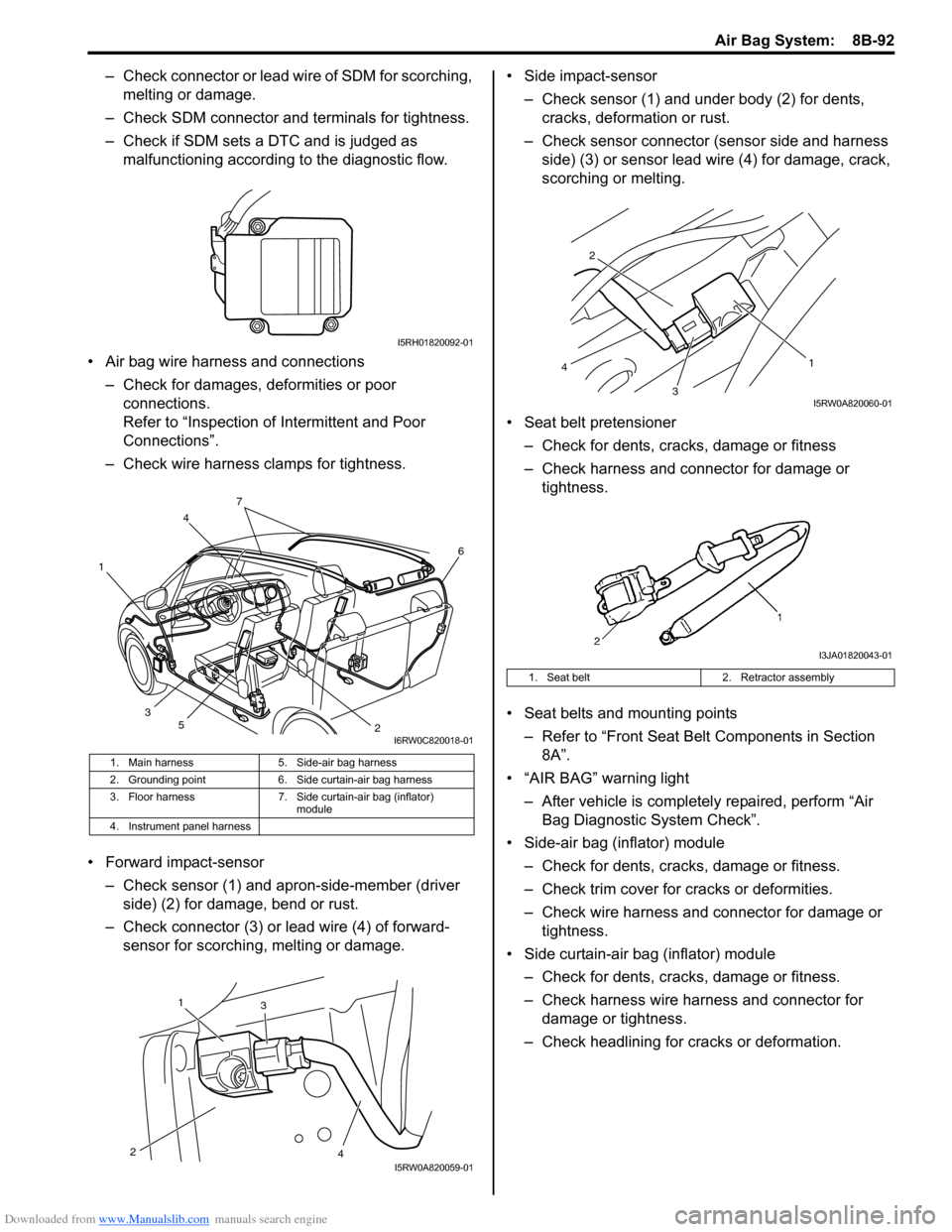
– Check connector or lead wire of SDM for scorching,
melting or damage.
– Check SDM connector and terminals for tightness.
– Check if SDM sets a DTC and is judged as
malfunctioning according to the diagnostic flow.
• Air bag wire harness and connections
– Check for damages, deformities or poor
connections.
Refer to “Inspection of Intermittent and Poor
Connections”.
– Check wire harness clamps for tightness.
• Forward impact-sensor
– Check sensor (1) and apron-side-member (driver
side) (2) for damage, bend or rust.
– Check connector (3) or lead wire (4) of forward-
sensor for scorching, melting or damage.• Side impact-sensor
– Check sensor (1) and under body (2) for dents,
cracks, deformation or rust.
– Check sensor connector (sensor side and harness
side) (3) or sensor lead wire (4) for damage, crack,
scorching or melting.
• Seat belt pretensioner
– Check for dents, cracks, damage or fitness
– Check harness and connector for damage or
tightness.
• Seat belts and mounting points
– Refer to “Front Seat Belt Components in Section
8A”.
• “AIR BAG” warning light
– After vehicle is completely repaired, perform “Air
Bag Diagnostic System Check”.
• Side-air bag (inflator) module
– Check for dents, cracks, damage or fitness.
– Check trim cover for cracks or deformities.
– Check wire harness and connector for damage or
tightness.
• Side curtain-air bag (inflator) module
– Check for dents, cracks, damage or fitness.
– Check harness wire harness and connector for
damage or tightness.
– Check headlining for cracks or deformation.
1. Main harness 5. Side-air bag harness
2. Grounding point 6. Side curtain-air bag harness
3. Floor harness 7. Side curtain-air bag (inflator)
module
4. Instrument panel harness
I5RH01820092-01
4
1
26
3
5
7
I6RW0C820018-01
1
23
4I5RW0A820059-01
1. Seat belt 2. Retractor assembly
3 2
1
4
I5RW0A820060-01
I3JA01820043-01
Page 1132 of 1556

Downloaded from www.Manualslib.com manuals search engine 8B-93 Air Bag System:
Repair Instructions
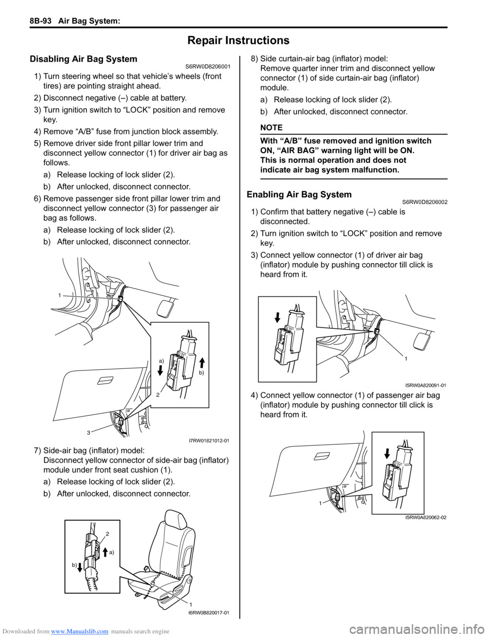
Disabling Air Bag SystemS6RW0D8206001
1) Turn steering wheel so that vehicle’s wheels (front
tires) are pointing straight ahead.
2) Disconnect negative (–) cable at battery.
3) Turn ignition switch to “LOCK” position and remove
key.
4) Remove “A/B” fuse from junction block assembly.
5) Remove driver side front pillar lower trim and
disconnect yellow connector (1) for driver air bag as
follows.
a) Release locking of lock slider (2).
b) After unlocked, disconnect connector.
6) Remove passenger side front pillar lower trim and
disconnect yellow connector (3) for passenger air
bag as follows.
a) Release locking of lock slider (2).
b) After unlocked, disconnect connector.
7) Side-air bag (inflator) model:
Disconnect yellow connector of side-air bag (inflator)
module under front seat cushion (1).
a) Release locking of lock slider (2).
b) After unlocked, disconnect connector.8) Side curtain-air bag (inflator) model:
Remove quarter inner trim and disconnect yellow
connector (1) of side curtain-air bag (inflator)
module.
a) Release locking of lock slider (2).
b) After unlocked, disconnect connector.
NOTE
With “A/B” fuse removed and ignition switch
ON, “AIR BAG” warning light will be ON.
This is normal operation and does not
indicate air bag system malfunction.
Enabling Air Bag SystemS6RW0D8206002
1) Confirm that battery negative (–) cable is
disconnected.
2) Turn ignition switch to “LOCK” position and remove
key.
3) Connect yellow connector (1) of driver air bag
(inflator) module by pushing connector till click is
heard from it.
4) Connect yellow connector (1) of passenger air bag
(inflator) module by pushing connector till click is
heard from it.
1
a)
b)
2
3
I7RW01821012-01
1
2
a)
b)
I6RW0B820017-01
1
I5RW0A820091-01
1
I5RW0A820062-02
Page 1162 of 1556

Downloaded from www.Manualslib.com manuals search engine 9-ii Table of Contents
B-9 Keyless Start System Circuit Diagram...... 9A-103
C-1 Combination Meter Circuit Diagram
(Meter) .......................................................... 9A-104
C-2 Combination Meter Circuit Diagram
(Indicator) ...................................................... 9A-105
C-3 Combination Meter Circuit Diagram
(Warning Light) ............................................. 9A-106
D-1 Headlight System Circuit Diagram
(Except Taiwan) ............................................ 9A-108
D-1 Headlight System Circuit Diagram
(Taiwan) ........................................................ 9A-110
D-2 Position, Tail and Licence Plate Light
System Circuit Diagram (Except Taiwan) ..... 9A-111
D-2 Position, Tail and Licence Plate Light
System Circuit Diagram (Taiwan) ................. 9A-112
D-3 Front Fog Light System Circuit Diagram
(Except Taiwan) ............................................ 9A-113
D-3 Front Fog Light System Circuit Diagram
(Taiwan) ........................................................ 9A-114
D-4 Illumination Light System Circuit Diagram
(Except Taiwan) ............................................ 9A-115
D-4 Illumination Light System Circuit Diagram
(Taiwan) ........................................................ 9A-116
D-5 Interior Light System Circuit Diagram
(Except Taiwan) ............................................ 9A-117
D-5 Interior Light System Circuit Diagram
(Taiwan) ........................................................ 9A-118
D-6 Turn Signal and Hazard Warning Light
System Circuit Diagram (Except Taiwan) ..... 9A-119
D-6 Turn Signal and Hazard Warning Light
System Circuit Diagram (Taiwan) ................. 9A-121
D-7 Brake Light System Circuit Diagram ........ 9A-123
D-8 Back-Up Light System Circuit Diagram .... 9A-124
D-9 Headlight Beam Leveling System Circuit
Diagram (Manual Leveling)........................... 9A-125
D-10 Rear Fog Light Circuit Diagram .............. 9A-126
E-1 Heater System Circuit Diagram ................ 9A-127
E-2 Auto A/C System Circuit Diagram ............ 9A-129
F-1 Air-Bag System Circuit Diagram (4ch) ...... 9A-131
F-1 Air-Bag System Circuit Diagram (8ch) ...... 9A-132
F-2 Anti-Lock Brake System Circuit Diagram.. 9A-134
F-4 Power Steering System Circuit Diagram .. 9A-136
G-1 Audio System Circuit Diagram ................. 9A-138
G-2 Multi Information Display / Accessory
Socket System Circuit Diagram .................... 9A-140
G-4 Navigation System Circuit Diagram ......... 9A-141
List of Connector .............................................9A-143
List of Connectors ........................................... 9A-143
C Connector .................................................... 9A-143
E Connector .................................................... 9A-145
G Connector .................................................... 9A-146
J Connector ..................................................... 9A-149
K Connector .................................................... 9A-149
L Connector..................................................... 9A-150
O Connector .................................................... 9A-152
Q Connector (8ch)........................................... 9A-152
R Connector .................................................... 9A-152
S Connector .................................................... 9A-152
Lighting Systems .................................... 9B-1
Precautions ...........................................................9B-1
Precautions for Discharge Headlight Service
(If Equipped)...................................................... 9B-1
Precautions in Diagnosing Troubles
(Headlight Auto Leveling System) ..................... 9B-1
General Description .............................................9B-1
Discharge Headlight Description (If
Equipped) .......................................................... 9B-1
Headlight Auto Leveling System Description
(If Equipped)...................................................... 9B-2
Auto-On Headlight System Description (If
Equipped) .......................................................... 9B-4
Schematic and Routing Diagram ........................9B-5
Headlight Auto Leveling System Wiring
Circuit Diagram ................................................. 9B-5
Component Location ...........................................9B-6
Lighting System Components Location............... 9B-6
Interior Light System Location............................. 9B-7
Diagnostic Information and Procedures ............9B-7
Self-Diagnosis Function for Headlight Auto
Leveling System ................................................ 9B-7
Headlight Leveling Warning Light Check ............ 9B-8
Headlight Symptom Diagnosis (Discharge
Headlight Model) ............................................... 9B-8
Headlight Symptom diagnosis (Other than
Discharge Headlight Model) .............................. 9B-9
Auto-On Headlight System Symptom
Diagnosis (If Equipped) ..................................... 9B-9
DRL System Symptom Diagnosis (If
Equipped) ........................................................ 9B-10
Headlight Auto Leveling System Symptom
Diagnosis (If Equipped) ................................... 9B-10
Headlight Manual Leveling System Symptom
Diagnosis (If Equipped) ................................... 9B-10
Turn Signal and Hazard Warning Light
Symptom Diagnosis ........................................ 9B-11
Clearance, Tail and License Plate Light
Symptom Diagnosis ........................................ 9B-11
Back-Up Light Symptom Diagnosis................... 9B-12
Brake Light Symptom Diagnosis ....................... 9B-12
Front Fog Light Symptom Diagnosis (If
Equipped) ........................................................ 9B-12
Rear Fog Light Symptom Diagnosis (If
Equipped) ........................................................ 9B-12
Illumination Cancel System Symptom
Diagnosis (If Equipped) ................................... 9B-13
Interior Light Symptom Diagnosis ..................... 9B-13
DRL Operation Inspection (If Equipped) ........... 9B-13
Inspection of DRL Controller and Its Circuits
(If Equipped).................................................... 9B-13
Auto-On Headlight Operation Inspection (If
Equipped) ........................................................ 9B-15
Inspection of Auto-On Headlight Controller
and Its Circuit (If Equipped)............................. 9B-15
Inspection of Headlight Leveling Control
Module and Its Circuit (Headlight Auto
Leveling System)............................................. 9B-16
Repair Instructions ............................................9B-18
Headlight Housing Removal and Installation .... 9B-18
Page 1163 of 1556

Downloaded from www.Manualslib.com manuals search engine Table of Contents 9-iii
Headlight Bulb Replacement (Discharge
Headlight Model) ............................................. 9B-19
Ballast Removal and Installation (Discharge
Headlight Model) ............................................. 9B-19
Igniter Removal and Installation (Discharge
Headlight Model) ............................................. 9B-20
Headlight Aiming Adjustment with Screen ........ 9B-20
Headlight Switch (in Lighting Switch)
Removal and Installation................................. 9B-22
Headlight Switch (in Lighting Switch)
Inspection........................................................ 9B-22
Hazard Warning Switch Removal and
Installation ....................................................... 9B-23
Hazard Warning Switch Inspection ................... 9B-23
Brake Light Switch Inspection ........................... 9B-23
Turn Signal Light Switch (in Lighting Switch)
Removal and Installation................................. 9B-24
Turn Signal Light Switch (in Lighting Switch)
Inspection........................................................ 9B-24
Turn Signal and Hazard Warning Relay
Removal and Installation................................. 9B-24
Turn Signal and Hazard Warning Relay
Inspection........................................................ 9B-25
License Light Assembly Removal and
Installation ....................................................... 9B-25
Front Fog Light Assembly Removal and
Installation (If Equipped) ................................. 9B-26
Front Fog Light Switch Inspection (If
Equipped)........................................................ 9B-26
Front Fog Light Aiming Adjustment with
Screen (If Equipped) ....................................... 9B-26
Rear Fog Light Switch Inspection (If
Equipped)........................................................ 9B-27
Headlight Manual Levering Switch Inspection
(If Equipped) ................................................... 9B-28
Headlight Leveling Actuator Inspection (If
Equipped)........................................................ 9B-28
Height Sensor Removal and Installation (If
Equipped)........................................................ 9B-29
Height Sensor and Its Circuit Inspection (If
Equipped)........................................................ 9B-30
Headlight Leveling Control Module Removal
and Installation (If Equipped) .......................... 9B-30
Initialization of Headlight Auto Leveling
System ............................................................ 9B-30
Auto-On Headlight Sensor Inspection (If
Equipped)........................................................ 9B-31
Illumination Cancel Switch Inspection (If
Equipped)........................................................ 9B-32
Tail Light Relay, Headlight Relay, Front Fog
Light Relay Inspection (If Equipped) ............... 9B-32
Specifications..................................................... 9B-33
Tightening Torque Specifications ...................... 9B-33
Instrumentation / Driver Info. / Horn ...... 9C-1
Precautions........................................................... 9C-1
Precautions in Diagnosing Troubles for
Combination Meter............................................ 9C-1
General Description ............................................. 9C-1
CAN Communication System Description........... 9C-1Auto Volume Control System Description (If
Equipped) ..........................................................9C-3
Schematic and Routing Diagram ........................9C-4
Combination Meter Circuit Diagram ....................9C-4
Component Location ...........................................9C-5
Audio System Component Location ....................9C-5
Diagnostic Information and Procedures ............9C-6
Speedometer and VSS Symptom Diagnosis ......9C-6
Tachometer Symptom Diagnosis ........................9C-6
Engine Coolant Temperature (ECT) Meter
Symptom Diagnosis ..........................................9C-6
Fuel Meter Symptom Diagnosis ..........................9C-6
Low Fuel Warning Light Symptom Diagnosis .....9C-7
Oil Pressure Warning Light Symptom
Diagnosis ..........................................................9C-7
Brake and Parking Brake Warning Light
Symptom Diagnosis ..........................................9C-8
Seat Belt Reminder Light Symptom Diagnosis ....9C-8
A/T Shift Position Indicator Symptom
Diagnosis (A/T Model).......................................9C-8
Charge Warning Light Symptom Diagnosis ........9C-9
Main Beam (High Beam) Indicator Symptom
Diagnosis ..........................................................9C-9
Warning Buzzer Circuit Symptom Diagnosis ......9C-9
Cigarette Lighter Symptom Diagnosis (If
Equipped) ........................................................9C-10
Horn Symptom Diagnosis .................................9C-10
Information Display Symptom Diagnosis (If
Equipped) ........................................................9C-10
Clock System Diagnosis (If Equipped) ..............9C-11
Audio System Symptom Diagnosis (If
Equipped) ........................................................9C-12
Remote Audio Control Switch Symptom
Diagnosis (If Equipped) ...................................9C-13
Navigation Symptom Diagnosis (If Equipped)...9C-13
Repair Instructions ............................................9C-14
Ignition Switch Removal and Installation...........9C-14
Ignition Switch Inspection..................................9C-14
Combination Meter Removal and Installation ...9C-14
Fuel Level Sensor Removal and Installation .....9C-15
Fuel Level Sensor Inspection ............................9C-15
Oil Pressure Switch Removal and Installation ..9C-15
Oil Pressure Switch Inspection .........................9C-15
Engine Coolant Temperature (ECT) Sensor
Inspection ........................................................9C-16
Brake Fluid Level Switch Inspection .................9C-16
Parking Brake Switch Inspection.......................9C-16
Door Switch (Front / Rear Door) Inspection ......9C-16
Rear End Door Switch Inspection .....................9C-16
Outside Air Temperature Sensor Removal
and Installation (If Equipped) ..........................9C-17
Outside Air Temperature Sensor Inspection
(If Equipped)....................................................9C-17
Instrument Panel Removal and Installation.......9C-17
Information Display (Clock) Removal and
Installation .......................................................9C-18
Audio Unit Removal and Installation (If
Equipped) ........................................................9C-19