2006 SUZUKI SX4 DTC U0100
[x] Cancel search: DTC U0100Page 672 of 1556

Downloaded from www.Manualslib.com manuals search engine 5A-24 Automatic Transmission/Transaxle:
Scan Tool DataS6RW0D5104008
As the data values given in the following table are standard values estimated on the basis of values obtained from the
normally operating vehicles by using a scan tool, use them as reference values. Even when the vehicle is in good
condition, there may be cases where the checked value does not fall within each specified data range. Therefore,
judgment as abnormal should not be made by checking with these data alone.
Also, condition in the following table that can be checked by the scan tool are those detected by TCM and output from
TCM as commands and there may be cases where the automatic transaxle or actuator is not operating (in the
condition) as indicated by the scan tool.
NOTE
The following scan tool data related to automatic transaxle can be checked only by communicating
with TCM.
�) U0100TCM lost communication with ECM
(Reception error)• Throttle opening used for line pressure control is assumed
to be 100%.
• Throttle opening used for gear shifting control is assumed
to be 0%.
• Engine revolution is assumed to be 0 RPM.
• After 15 minutes pass from detecting malfunction, engine
coolant temperature is assumed to be 90 °C (194 °F).
• Lock-up function is inhibited to operate.
• Slip controlled lock-up function is inhibited to operate.
• Line pressure control at gear shifting is inhibited.
• Torque reducing request to ECM (torque reduction control)
is inhibited.
• Upshifting to 4th gear is inhibited.
• Garage shift control is inhibited.
• Learning control is inhibited. DTC No. Trouble area Fail-safe operation
Scan tool data Vehicle conditionNormal condition / reference
values
�) GEAR POSITION Ignition switch ONSelect lever is in “P” position P or N
Select lever is in “R” position R
Select lever is in “N” position P or N
Select lever is in “D” position 1
Select lever is in “3” position 1
Select lever is in “2” position 1
Select lever is in “L” position 1
�) ENGINE SPEED At engine idle speed Engine idle speed is displayed
�) INPUT SHAFT
REVOLUTIONIgnition switch ON and engine stop 0 RPM
At 60 km/h (37.5 mile/h) constant speed, 20% or less
throttle opening and 3rd gear (“3” range)2300 RPM
(displayed in increments of 0.25 rpm)
�) OUTPUT SHAFT
REVOLUTIONAt vehicle stop 0 RPM
At 60 km/h (37.5 mile/h) constant speed, 20% or less
throttle opening and 3rd gear (“3” range)2300 RPM
(displayed in increments of 0.25 rpm)
�) BATTERY
VOLTAGEIgnition switch ON and engine stopBattery voltage is displayed
(8 – 16 V)
�) AT F
TEMPERATUREAfter driving at 60 km/h (37.5 mile/h) for 15 minutes or
more, and A/T fluid temperature around sensor
reaches 70 – 80 °C (158 – 176 °F)70 – 80 °C (158 – 176 °F)
�) SHIFT SOLENOID-
A COMMANDAt vehicle stop ON
At 60 km/h (37.5 mile/h) constant speed, 20% or less
throttle opening and 3rd gear (“3” range)OFF
�) SHIFT SOLENOID-
A MONITORAt vehicle stop ON
At 60 km/h (37.5 mile/h) constant speed, 20% or less
throttle opening and 3rd gear (“3” range)OFF
Page 689 of 1556

Downloaded from www.Manualslib.com manuals search engine Automatic Transmission/Transaxle: 5A-41
Transmission Warning Light Circuit Check – Light Remains “ON” at Ignition Switch ON (Non-Euro-
OBD Model)
S6RW0D5104054
Troubleshooting
Transmission Warning Light Circuit Check – Light Does Not Come “ON” at Ignition Switch ON (Non-
Euro-OBD Model)
S6RW0D5104055
TroubleshootingNon operate TCC (lock-
up) systemFaulty torque converterReplace.
Excessive “N”
→ “D” time
lagFaulty oil pumpInspect. If NG, replace.
Faulty forward clutchInspect. If NG, replace.
Faulty one-way No.2 clutchInspect. If NG, replace.
Leakage from “D” range fluid pressure
circuitOverhaul or replace valve body assembly.
Excessive “N”
→ “R” time
lagFaulty oil pumpInspect. If NG, replace.
Faulty reverse clutchInspect. If NG, replace.
Faulty 1st and reverse brakeInspect. If NG, replace.
Leakage from “R” range fluid pressure
circuitOverhaul or replace valve body assembly.
Poor engine brake in
downshift to “2” rangeFaulty O/D and 2nd coast brakeInspect. If NG, replace.
Poor engine brake in
downshift to “L” rangeFaulty 1st and reverse brakeInspect. If NG, replace. Condition Possible cause Correction / Reference Item
Step Action Yes No
1Diagnostic Trouble Code (DTC) Check
1) Check DTC referring to “DTC Check”.
Is there any DTC(s)?Perform DTC Flow to
repair and retry.Substitute a known-
good TCM and recheck.
If OK, substitute a
known-good
combination meter and
recheck.
Step Action Yes No
1Combination Meter Power Supply Check
1) Turn ignition switch ON.
Does other indicator / warning lights in combination meter
comes ON?Go to Step 2. Repair combination
meter power supply
circuit referring to
“Combination Meter
Circuit Diagram in
Section 9C”.
2 1) TCM power and ground circuit check referring to “TCM
Power and Ground Circuit Check”.
Is it in good condition?Go to Step 3. Repair or replace.
3DTC check
1) Check DTC referring to “DTC Check”.
Is there DTC U0073 or U0100?Go to applicable DTC
diag. flow.Go to Step 4.
4Combination Meter Function Check
1) Turn ignition switch ON.
Does A/T selector position indicator show correct select
lever position?Replace combination
meter.Substitute a known-
good TCM and recheck.
Page 724 of 1556

Downloaded from www.Manualslib.com manuals search engine 5A-76 Automatic Transmission/Transaxle:
DTC U0073: Control Module Communication Bus OffS6RW0D5104051
Refer to “Troubleshooting for CAN-DTC in Section 1A”.
DTC U0100: Lost Communication with ECM / PCM “A”S6RW0D5104052
Refer to “Troubleshooting for CAN-DTC in Section 1A”.
Inspection of TCM and Its CircuitsS6RW0D5104044
TCM and its circuits can be checked at TCM wiring connectors by measuring voltage, pulse signal and resistance.
CAUTION!
TCM cannot be checked by itself, it is strictly prohibited to connect voltmeter or ohmmeter to TCM with
connector disconnected from it.
1) Remove TCM (1) from vehicle referring to “Transmission Control Module (TCM) Removal and Installation”.
2) Connect TCM connectors (2) to TCM.
3) Check voltage and/or pulse signal at each terminal of connectors connected using voltmeter (3) and oscilloscope
(4).
NOTE
• As each terminal voltage is affected by battery voltage, confirm that it is 11 V or more when ignition
switch is ON.
• Voltage with asterisk(*) cannot be measured by voltmeter because it is pulse signal. Check it with
oscilloscope if necessary.
Terminal arrangement of TCM coupler (Viewed from harness side)
3
4
12
I4RS0A510021-02
65
16 15 14 13 12 1143
24 23 212210 9 8 721
19 20 18 17 C06
17 16
26 2515 14 65 342
13 12
23 22 2411 10 9
21 20 1987
18 1 C07
I6RW0B510018-01
Page 1012 of 1556
Downloaded from www.Manualslib.com manuals search engine 7B-72 Air Conditioning System: Automatic Type
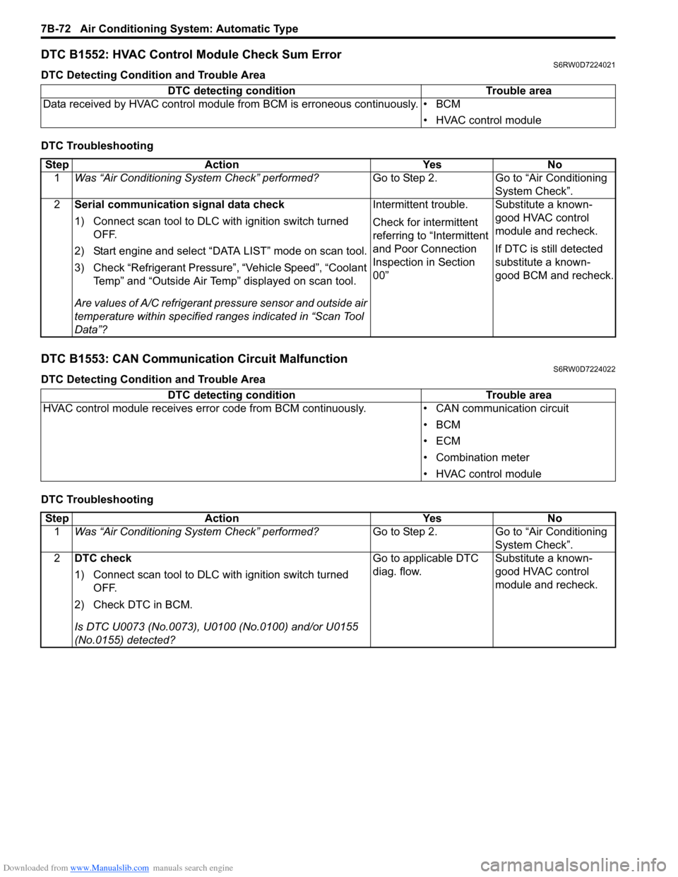
DTC B1552: HVAC Control Module Check Sum ErrorS6RW0D7224021
DTC Detecting Condition and Trouble Area
DTC Troubleshooting
DTC B1553: CAN Communication Circuit MalfunctionS6RW0D7224022
DTC Detecting Condition and Trouble Area
DTC TroubleshootingDTC detecting condition Trouble area
Data received by HVAC control module from BCM is erroneous continuously. • BCM
• HVAC control module
Step Action Yes No
1Was “Air Conditioning System Check” performed?Go to Step 2. Go to “Air Conditioning
System Check”.
2Serial communication signal data check
1) Connect scan tool to DLC with ignition switch turned
OFF.
2) Start engine and select “DATA LIST” mode on scan tool.
3) Check “Refrigerant Pressure”, “Vehicle Speed”, “Coolant
Temp” and “Outside Air Temp” displayed on scan tool.
Are values of A/C refrigerant pressure sensor and outside air
temperature within specified ranges indicated in “Scan Tool
Data”?Intermittent trouble.
Check for intermittent
referring to “Intermittent
and Poor Connection
Inspection in Section
00”Substitute a known-
good HVAC control
module and recheck.
If DTC is still detected
substitute a known-
good BCM and recheck.
DTC detecting condition Trouble area
HVAC control module receives error code from BCM continuously. • CAN communication circuit
•BCM
•ECM
• Combination meter
• HVAC control module
Step Action Yes No
1Was “Air Conditioning System Check” performed?Go to Step 2. Go to “Air Conditioning
System Check”.
2DTC check
1) Connect scan tool to DLC with ignition switch turned
OFF.
2) Check DTC in BCM.
Is DTC U0073 (No.0073), U0100 (No.0100) and/or U0155
(No.0155) detected?Go to applicable DTC
diag. flow.Substitute a known-
good HVAC control
module and recheck.
Page 1471 of 1556
Downloaded from www.Manualslib.com manuals search engine Table of Contents 10- i
10
Section 10
CONTENTS
Control Systems
Precautions ............................................... 10-1
Precautions........................................................... 10-1
Precautions for Control Systems......................... 10-1
Body Electrical Control System ........... 10B-1
Precautions......................................................... 10B-1
Precautions in Diagnosing Trouble ................... 10B-1
General Description ........................................... 10B-1
BCM General Description ................................. 10B-1
CAN Communication System Description......... 10B-1
Theft Deterrent Light ......................................... 10B-2
Security Alarm Description (If Equipped) .......... 10B-2
Schematic and Routing Diagram ...................... 10B-3
Body Electrical Control System Wiring Circuit
Diagram .......................................................... 10B-3
Connector Layout Diagram of BCM and
Junction Block ................................................. 10B-6
Component Location ......................................... 10B-7
BCM and Related System Component
Location .......................................................... 10B-7
Diagnostic Information and Procedures .......... 10B-8
BCM Self-Diagnosis Function ........................... 10B-8
Body Electrical Control System Check.............. 10B-9
Scan Tool Data ............................................... 10B-11
DTC Table ....................................................... 10B-13
DTC Check ..................................................... 10B-14
DTC Clearance ............................................... 10B-15
BCM Power Circuit and Ground Circuit Check 10B-16
DTC B1133 (DTC No. 1133): Battery Voltage
Too High ....................................................... 10B-17
DTC B1141 / DTC B1142 (No. 1141 / No.
1142) Outside Air Temperature (Ambient
Temp.) Sensor Circuit Malfunction ................ 10B-18
DTC B1150 (No. 1150): Air Bag
Communication Circuit Malfunction .............. 10B-19
DTC B1157 (No. 1157) Air Bag Deployment
Signal Input ................................................... 10B-20
DTC B1170 (No. 1170): EEPROM Access
Error .............................................................. 10B-20
DTC U0073 (No. 0073): Control Module
Communication Bus Off ................................ 10B-20
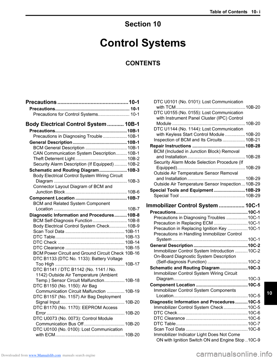
DTC U0100 (No. 0100): Lost Communication
with ECM....................................................... 10B-20DTC U0101 (No. 0101): Lost Communication
with TCM ....................................................... 10B-20
DTC U0155 (No. 0155): Lost Communication
with Instrument Panel Cluster (IPC) Control
Module .......................................................... 10B-20
DTC U1144 (No. 1144): Lost Communication
with Keyless Start Control Module ................ 10B-20
Inspection of BCM and Its Circuits .................. 10B-21
Repair Instructions ..........................................10B-28
BCM (Included in Junction Block) Removal
and Installation .............................................. 10B-28
Security Alarm Mode Selection Procedure (If
Equipped) ...................................................... 10B-29
Outside Air Temperature Sensor Removal
and Installation .............................................. 10B-29
Outside Air Temperature Sensor Inspection ... 10B-29
Special Tools and Equipment .........................10B-29
Special Tool .................................................... 10B-29
Immobilizer Control System ................. 10C-1
Precautions.........................................................10C-1
Precautions in Diagnosing Troubles .................10C-1
Precaution in Replacing ECM ...........................10C-1
Precaution in Replacing Ignition Key ................10C-1
Precautions in Handling Immobilizer Control
System ............................................................10C-1
General Description ...........................................10C-2
Immobilizer Control System Introduction ..........10C-2
On-Board Diagnostic System Description
(Self-diagnosis Function)................................10C-2
Schematic and Routing Diagram ......................10C-3
Immobilizer Control System Wiring Circuit
Diagram...........................................................10C-3
Component Location .........................................10C-5
Immobilizer Control System Components
Location...........................................................10C-5
Diagnostic Information and Procedures ..........10C-5
Immobilizer Control System Check ...................10C-5
DTC Check........................................................10C-6
DTC Clearance .................................................10C-6
DTC Table .........................................................10C-7
Scan Tool Data .................................................10C-8
Immobilizer Indicator Light Does Not Come
ON with Ignition Switch ON and Engine Stop ..10C-9
Page 1486 of 1556
Downloaded from www.Manualslib.com manuals search engine 10B-13 Body Electrical Control System:
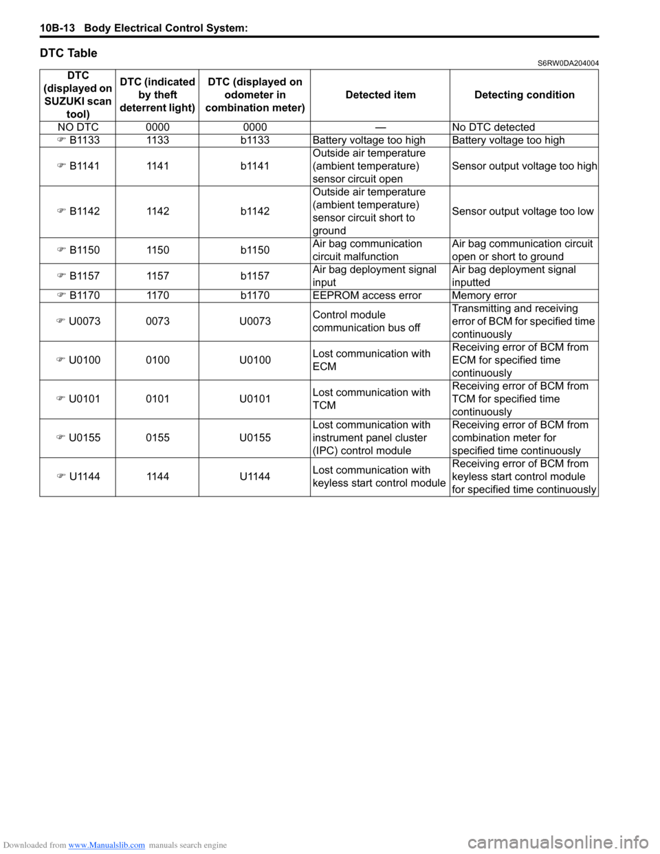
DTC TableS6RW0DA204004
DTC
(displayed on
SUZUKI scan
tool)DTC (indicated
by theft
deterrent light) DTC (displayed on
odometer in
combination meter) Detected item Detecting condition
NO DTC 0000 0000 — No DTC detected
�) B1133 1133 b1133 Battery voltage too high Battery voltage too high
�) B1141 1141 b1141Outside air temperature
(ambient temperature)
sensor circuit openSensor output voltage too high
�) B1142 1142 b1142Outside air temperature
(ambient temperature)
sensor circuit short to
groundSensor output voltage too low
�) B1150 1150 b1150Air bag communication
circuit malfunctionAir bag communication circuit
open or short to ground
�) B1157 1157 b1157Air bag deployment signal
inputAir bag deployment signal
inputted
�) B1170 1170 b1170 EEPROM access error Memory error
�) U0073 0073 U0073Control module
communication bus offTransmitting and receiving
error of BCM for specified time
continuously
�) U0100 0100 U0100Lost communication with
ECMReceiving error of BCM from
ECM for specified time
continuously
�) U0101 0101 U0101Lost communication with
TCMReceiving error of BCM from
TCM for specified time
continuously
�) U0155 0155 U0155Lost communication with
instrument panel cluster
(IPC) control moduleReceiving error of BCM from
combination meter for
specified time continuously
�) U1144 1144 U1144Lost communication with
keyless start control moduleReceiving error of BCM from
keyless start control module
for specified time continuously
Page 1493 of 1556
Downloaded from www.Manualslib.com manuals search engine Body Electrical Control System: 10B-20
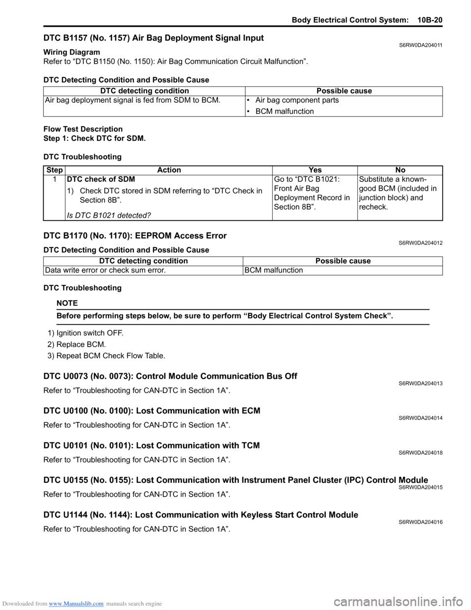
DTC B1157 (No. 1157) Air Bag Deployment Signal InputS6RW0DA204011
Wiring Diagram
Refer to “DTC B1150 (No. 1150): Air Bag Communication Circuit Malfunction”.
DTC Detecting Condition and Possible Cause
Flow Test Description
Step 1: Check DTC for SDM.
DTC Troubleshooting
DTC B1170 (No. 1170): EEPROM Access ErrorS6RW0DA204012
DTC Detecting Condition and Possible Cause
DTC Troubleshooting
NOTE
Before performing steps below, be sure to perform “Body Electrical Control System Check”.
1) Ignition switch OFF.
2) Replace BCM.
3) Repeat BCM Check Flow Table.
DTC U0073 (No. 0073): Control Module Communication Bus OffS6RW0DA204013
Refer to “Troubleshooting for CAN-DTC in Section 1A”.
DTC U0100 (No. 0100): Lost Communication with ECMS6RW0DA204014
Refer to “Troubleshooting for CAN-DTC in Section 1A”.
DTC U0101 (No. 0101): Lost Communication with TCMS6RW0DA204018
Refer to “Troubleshooting for CAN-DTC in Section 1A”.
DTC U0155 (No. 0155): Lost Communication with Instrument Panel Cluster (IPC) Control ModuleS6RW0DA204015
Refer to “Troubleshooting for CAN-DTC in Section 1A”.
DTC U1144 (No. 1144): Lost Communication with Keyless Start Control ModuleS6RW0DA204016
Refer to “Troubleshooting for CAN-DTC in Section 1A”. DTC detecting condition Possible cause
Air bag deployment signal is fed from SDM to BCM. • Air bag component parts
• BCM malfunction
Step Action Yes No
1DTC check of SDM
1) Check DTC stored in SDM referring to “DTC Check in
Section 8B”.
Is DTC B1021 detected?Go to “DTC B1021:
Front Air Bag
Deployment Record in
Section 8B”.Substitute a known-
good BCM (included in
junction block) and
recheck.
DTC detecting condition Possible cause
Data write error or check sum error. BCM malfunction
Page 1511 of 1556
Downloaded from www.Manualslib.com manuals search engine Immobilizer Control System: 10C-9
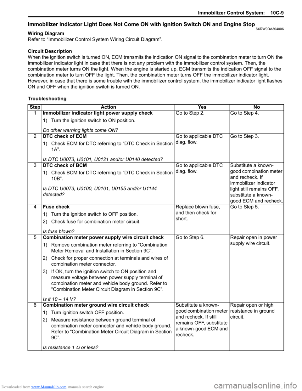
Immobilizer Indicator Light Does Not Come ON with Ignition Switch ON and Engine StopS6RW0DA304006
Wiring Diagram
Refer to “Immobilizer Control System Wiring Circuit Diagram”.
Circuit Description
When the ignition switch is turned ON, ECM transmits the indication ON signal to the combination meter to turn ON the
immobilizer indicator light in case that there is not any problem with the immobilizer control system. Then, the
combination meter turns ON the light. When the engine is started up, ECM transmits the indication OFF signal to the
combination meter to turn OFF the light. Then, the combination meter turns OFF the immobilizer indicator light.
However, in case that there is some trouble with the immobilizer control system, the immobilizer indicator light flashes
ON and OFF when the ignition switch is turned ON.
Troubleshooting
Step Action Yes No
1Immobilizer indicator light power supply check
1) Turn the ignition switch to ON position.
Do other warning lights come ON?Go to Step 2. Go to Step 4.
2DTC check of ECM
1) Check ECM for DTC referring to “DTC Check in Section
1A”.
Is DTC U0073, U0101, U0121 and/or U0140 detected?Go to applicable DTC
diag. flow.Go to Step 3.
3DTC check of BCM
1) Check BCM for DTC referring to “DTC Check in Section
10B”.
Is DTC U0073, U0100, U0101, U0155 and/or U1144
detected?Go to applicable DTC
diag. flow.Substitute a known-
good combination meter
and recheck. If
immobilizer indicator
light still remains OFF,
substitute a known-
good ECM and recheck.
4Fuse check
1) Turn the ignition switch to OFF position.
2) Check fuse for combination meter circuit.
Is fuse blown?Replace blown fuse,
and then check for
short.Go to Step 5.
5Combination meter power supply wire circuit check
1) Remove combination meter referring to “Combination
Meter Removal and Installation in Section 9C”.
2) Check for proper connection at terminals and wires of
combination meter connector.
3) If OK, turn the ignition switch to ON position and
measure voltage between power supply terminal of
combination meter and vehicle body ground. Refer to
“Combination Meter Circuit Diagram in Section 9C”.
Is it 10 – 14 V?Go to Step 6. Repair open in power
supply wire circuit.
6Combination meter ground wire circuit check
1) Turn ignition switch OFF position.
2) Measure resistance between ground terminal of
combination meter connector and vehicle body ground.
Refer to “Combination Meter Circuit Diagram in Section
9C”.
Is resistance 1
Ω or less?Substitute a known-
good combination meter
and recheck. If still
remains OFF, substitute
a known-good ECM and
recheck.Repair open or high
resistance in ground
circuit.