Page 1488 of 1556
Downloaded from www.Manualslib.com manuals search engine 10B-15 Body Electrical Control System:
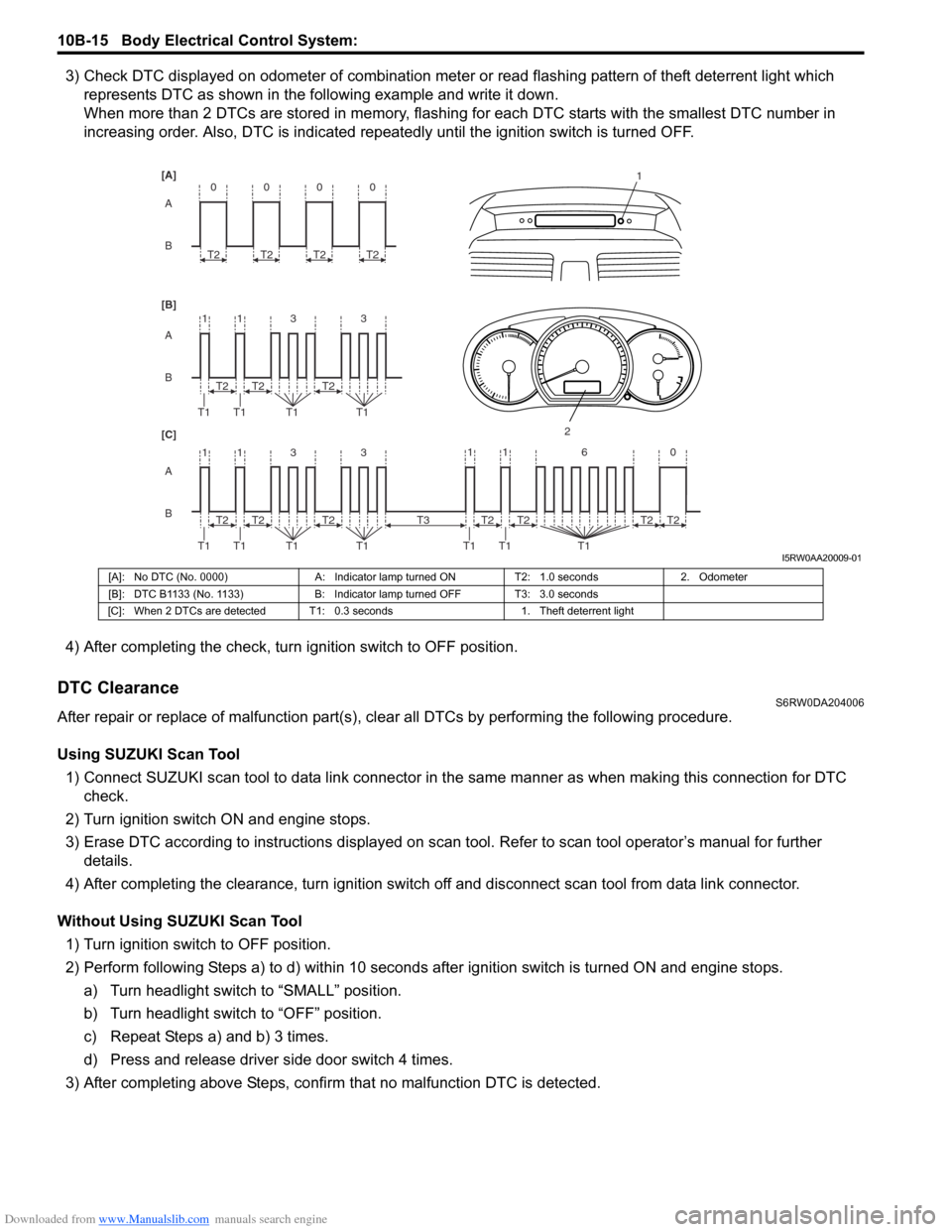
3) Check DTC displayed on odometer of combination meter or read flashing pattern of theft deterrent light which
represents DTC as shown in the following example and write it down.
When more than 2 DTCs are stored in memory, flashing for each DTC starts with the smallest DTC number in
increasing order. Also, DTC is indicated repeatedly until the ignition switch is turned OFF.
4) After completing the check, turn ignition switch to OFF position.
DTC ClearanceS6RW0DA204006
After repair or replace of malfunction part(s), clear all DTCs by performing the following procedure.
Using SUZUKI Scan Tool
1) Connect SUZUKI scan tool to data link connector in the same manner as when making this connection for DTC
check.
2) Turn ignition switch ON and engine stops.
3) Erase DTC according to instructions displayed on scan tool. Refer to scan tool operator’s manual for further
details.
4) After completing the clearance, turn ignition switch off and disconnect scan tool from data link connector.
Without Using SUZUKI Scan Tool
1) Turn ignition switch to OFF position.
2) Perform following Steps a) to d) within 10 seconds after ignition switch is turned ON and engine stops.
a) Turn headlight switch to “SMALL” position.
b) Turn headlight switch to “OFF” position.
c) Repeat Steps a) and b) 3 times.
d) Press and release driver side door switch 4 times.
3) After completing above Steps, confirm that no malfunction DTC is detected.
B A [B] [A]
[C]
B A B A
3 113
3 113 T2
T1 T1 T1T1
1
2
T2T2
T2
T1 T1 T1T1T2T2
0
T2
0
T2
0
T2
0
T2
11 6 0
T1 T1 T1
T2 T3T2T2T2
I5RW0AA20009-01
[A]: No DTC (No. 0000) A: Indicator lamp turned ON T2: 1.0 seconds 2. Odometer
[B]: DTC B1133 (No. 1133) B: Indicator lamp turned OFF T3: 3.0 seconds
[C]: When 2 DTCs are detected T1: 0.3 seconds 1. Theft deterrent light
Page 1489 of 1556
Downloaded from www.Manualslib.com manuals search engine Body Electrical Control System: 10B-16
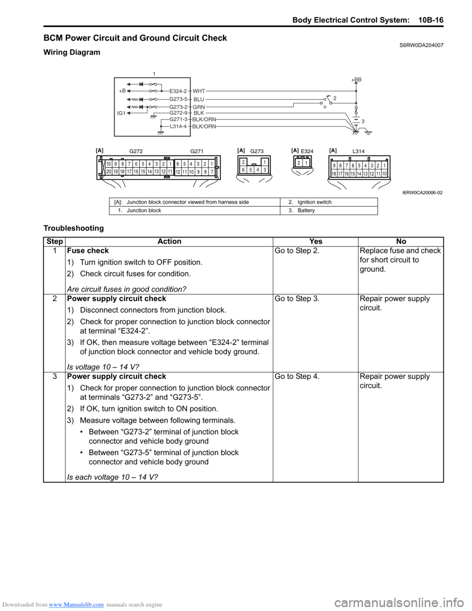
BCM Power Circuit and Ground Circuit CheckS6RW0DA204007
Wiring Diagram
Troubleshooting
+B
IG1
+BB
GRNG273-2BLKBLK/ORNG272-9
G271-3
BLK/ORNL314-4
BLU G273-5
WHTE324-22
3
1
E324 L314
1 2 4 53 6 7 8 9
10
11 12 13 14 15 16 17 181 21 2 4 53 61
2 4 53 6 7 8 9 10
7 8 9 10 11 12
11 12 13 14 15 16 17 18 19 20
G272 G271
1 2
4
65
G273[A] [A] [A]
3
[A]
I6RW0CA20006-02
[A]: Junction block connector viewed from harness side 2. Ignition switch
1. Junction block 3. Battery
Step Action Yes No
1Fuse check
1) Turn ignition switch to OFF position.
2) Check circuit fuses for condition.
Are circuit fuses in good condition?Go to Step 2. Replace fuse and check
for short circuit to
ground.
2Power supply circuit check
1) Disconnect connectors from junction block.
2) Check for proper connection to junction block connector
at terminal “E324-2”.
3) If OK, then measure voltage between “E324-2” terminal
of junction block connector and vehicle body ground.
Is voltage 10 – 14 V?Go to Step 3. Repair power supply
circuit.
3Power supply circuit check
1) Check for proper connection to junction block connector
at terminals “G273-2” and “G273-5”.
2) If OK, turn ignition switch to ON position.
3) Measure voltage between following terminals.
• Between “G273-2” terminal of junction block
connector and vehicle body ground
• Between “G273-5” terminal of junction block
connector and vehicle body ground
Is each voltage 10 – 14 V?Go to Step 4. Repair power supply
circuit.
Page 1490 of 1556
Downloaded from www.Manualslib.com manuals search engine 10B-17 Body Electrical Control System:
DTC B1133 (DTC No. 1133): Battery Voltage Too HighS6RW0DA204008
Wiring Diagram
Refer to “BCM Power Circuit and Ground Circuit Check”.
DTC Detecting Condition and Possible Cause
Flow Test Description
Step 1: Check charging system
DTC Troubleshooting4Ground circuit check
1) Turn ignition switch to OFF position.
2) Check for proper connection to junction block connector
at terminals “G271-3”, “G272-9” and “L314-4”.
3) If OK, then measure resistance between following
terminals.
• Between “G271-3” terminal of junction block
connector and vehicle body ground
• Between “G272-9” terminal of junction block
connector and vehicle body ground
• Between “L314-4” terminal of junction block connector
and vehicle body ground
Is each resistance 2
Ω or less?BCM power supply
circuit and ground circuit
are in good condition.Repair ground circuit. Step Action Yes No
DTC detecting condition Possible cause
Power voltage supplied from battery to BCM is
higher than 16V.• Charging system malfunction
• BCM malfunction
Step Action Yes No
1Charging system operation check
1) Check generator for operation referring to “Generator
Test (Overcharged Battery Check) in Section 1J”.
Is it in good condition?Substitute a known
good BCM (included in
junction block) and
recheck.Repair charging system.
Page 1491 of 1556
Downloaded from www.Manualslib.com manuals search engine Body Electrical Control System: 10B-18
DTC B1141 / DTC B1142 (No. 1141 / No. 1142) Outside Air Temperature (Ambient Temp.) Sensor
Circuit Malfunction
S6RW0DA204009
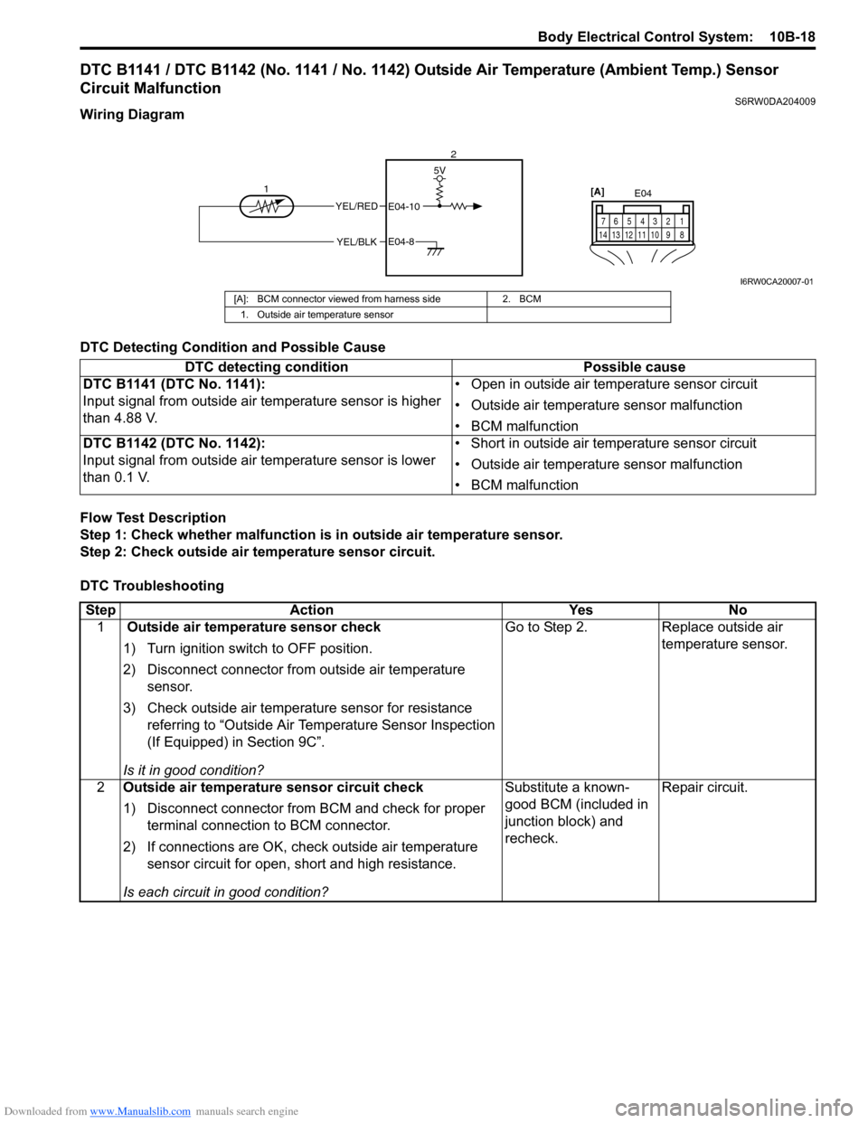
Wiring Diagram
DTC Detecting Condition and Possible Cause
Flow Test Description
Step 1: Check whether malfunction is in outside air temperature sensor.
Step 2: Check outside air temperature sensor circuit.
DTC Troubleshooting
YEL/RED
YEL/BLK
5V
E04-10
E04-8
12E04
1 2 4 53 6 7
8 9 10 11 12 13 14
[A]
I6RW0CA20007-01
[A]: BCM connector viewed from harness side 2. BCM
1. Outside air temperature sensor
DTC detecting condition Possible cause
DTC B1141 (DTC No. 1141):
Input signal from outside air temperature sensor is higher
than 4.88 V.• Open in outside air temperature sensor circuit
• Outside air temperature sensor malfunction
• BCM malfunction
DTC B1142 (DTC No. 1142):
Input signal from outside air temperature sensor is lower
than 0.1 V.• Short in outside air temperature sensor circuit
• Outside air temperature sensor malfunction
• BCM malfunction
Step Action Yes No
1 Outside air temperature sensor check
1) Turn ignition switch to OFF position.
2) Disconnect connector from outside air temperature
sensor.
3) Check outside air temperature sensor for resistance
referring to “Outside Air Temperature Sensor Inspection
(If Equipped) in Section 9C”.
Is it in good condition?Go to Step 2. Replace outside air
temperature sensor.
2Outside air temperature sensor circuit check
1) Disconnect connector from BCM and check for proper
terminal connection to BCM connector.
2) If connections are OK, check outside air temperature
sensor circuit for open, short and high resistance.
Is each circuit in good condition?Substitute a known-
good BCM (included in
junction block) and
recheck.Repair circuit.
Page 1492 of 1556
Downloaded from www.Manualslib.com manuals search engine 10B-19 Body Electrical Control System:
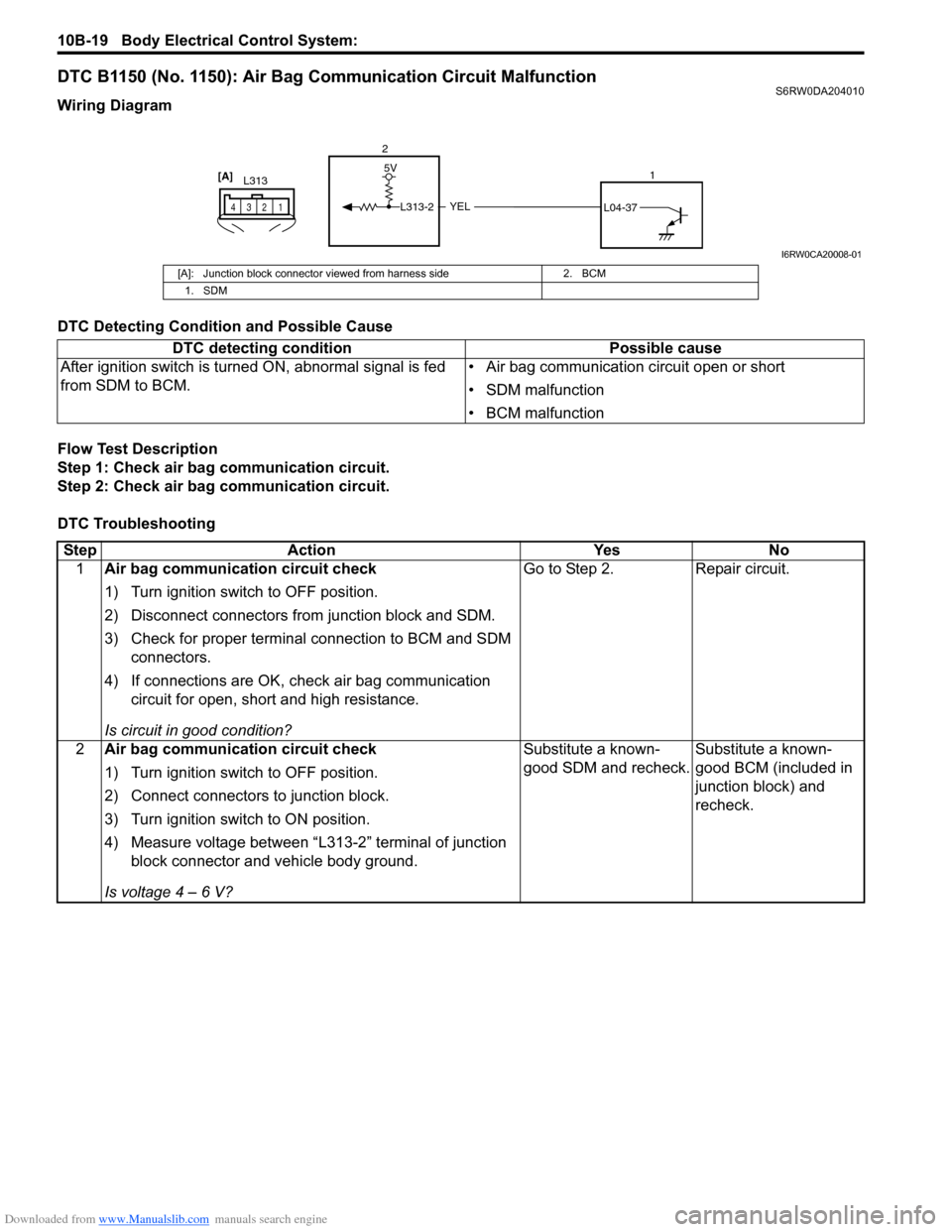
DTC B1150 (No. 1150): Air Bag Communication Circuit MalfunctionS6RW0DA204010
Wiring Diagram
DTC Detecting Condition and Possible Cause
Flow Test Description
Step 1: Check air bag communication circuit.
Step 2: Check air bag communication circuit.
DTC Troubleshooting
YEL
5V
L313-2L04-37
2
1
L313
1 2 43
[A]
I6RW0CA20008-01
[A]: Junction block connector viewed from harness side 2. BCM
1. SDM
DTC detecting condition Possible cause
After ignition switch is turned ON, abnormal signal is fed
from SDM to BCM.• Air bag communication circuit open or short
• SDM malfunction
• BCM malfunction
Step Action Yes No
1Air bag communication circuit check
1) Turn ignition switch to OFF position.
2) Disconnect connectors from junction block and SDM.
3) Check for proper terminal connection to BCM and SDM
connectors.
4) If connections are OK, check air bag communication
circuit for open, short and high resistance.
Is circuit in good condition?Go to Step 2. Repair circuit.
2Air bag communication circuit check
1) Turn ignition switch to OFF position.
2) Connect connectors to junction block.
3) Turn ignition switch to ON position.
4) Measure voltage between “L313-2” terminal of junction
block connector and vehicle body ground.
Is voltage 4 – 6 V?Substitute a known-
good SDM and recheck.Substitute a known-
good BCM (included in
junction block) and
recheck.