Page 818 of 1556

Downloaded from www.Manualslib.com manuals search engine 5B-6 Manual Transmission/Transaxle:
Manual Transaxle Oil ChangeS6RW0D5206002
1) Before changing or inspecting oil, be sure to stop
engine and lift vehicle horizontally.
2) With vehicle lifted up, check leakage.
If leakage exists, correct it.
NOTE
Whenever vehicle is hoisted for any other
service work than oil change, also be sure to
check for oil leakage.
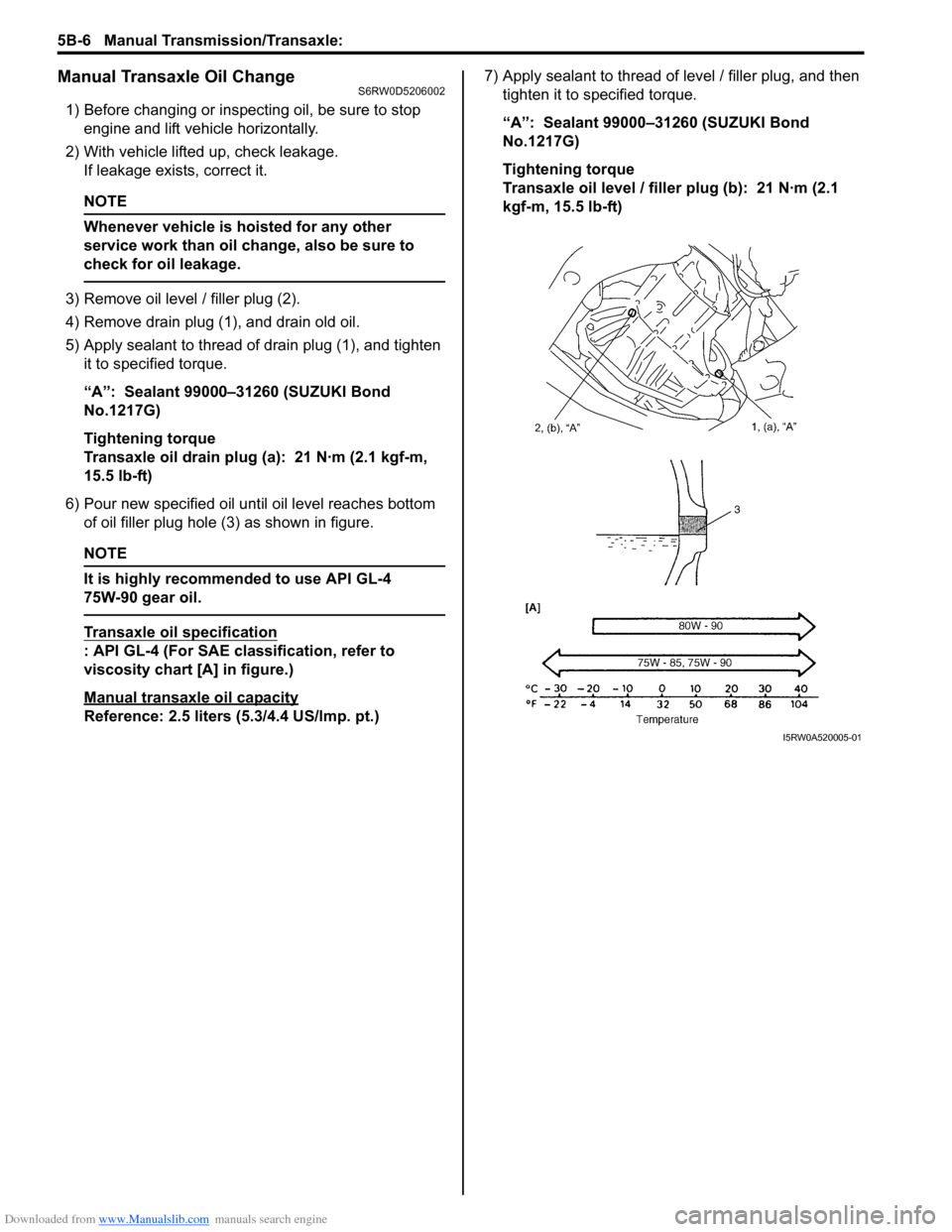
3) Remove oil level / filler plug (2).
4) Remove drain plug (1), and drain old oil.
5) Apply sealant to thread of drain plug (1), and tighten
it to specified torque.
“A”: Sealant 99000–31260 (SUZUKI Bond
No.1217G)
Tightening torque
Transaxle oil drain plug (a): 21 N·m (2.1 kgf-m,
15.5 lb-ft)
6) Pour new specified oil until oil level reaches bottom
of oil filler plug hole (3) as shown in figure.
NOTE
It is highly recommended to use API GL-4
75W-90 gear oil.
Transaxle oil specification
: API GL-4 (For SAE classification, refer to
viscosity chart [A] in figure.)
Manual transaxle oil capacity
Reference: 2.5 liters (5.3/4.4 US/lmp. pt.)7) Apply sealant to thread of level / filler plug, and then
tighten it to specified torque.
“A”: Sealant 99000–31260 (SUZUKI Bond
No.1217G)
Tightening torque
Transaxle oil level / filler plug (b): 21 N·m (2.1
kgf-m, 15.5 lb-ft)
I5RW0A520005-01
Page 834 of 1556

Downloaded from www.Manualslib.com manuals search engine 5B-22 Manual Transmission/Transaxle:
6) Clean mating surfaces of both right and left cases,
apply sealant to left case (2) as shown in the figure
by such amount that its section is 1.5 mm (0.059 in.)
in diameter then mate it with right case (1).
“A”: Sealant 99000–31260 (SUZUKI Bond
No.1217G)
7) Tighten case bolts (3) from outside and tighten
another case bolts from clutch housing side to
specified torque.
Tightening torque
Transaxle case bolt (a): 23 N·m (2.3 kgf-m, 17.0
lb-ft)
8) Install reverse shaft bolt (4) to which thread lock
cement has been applied, with aluminum washer
and tighten it to specified torque.
“B”: Sealant 99000–31260 (SUZUKI Bond
No.1217G)
Tightening torque
Reverse shaft bolt (b): 23 N·m (2.3 kgf-m, 17.0
lb-ft)9) Check locating springs (2, 4 and 5) for deterioration
and replace with new ones as necessary.
Locating spring
10) Install steel balls (3) and locating springs (2, 4 and 5)
for respective gear shift shaft and tighten bolts (1) to
which thread lock cement has been applied.
“A”: Thread lock cement 99000–32110 (Thread
Lock Cement Super 1322)
Tightening torque
Gear shift locating bolt (a): 13 N·m (1.3 kgf-m,
9.5 lb-ft)
11) Install new snap ring (1) using special tool.
Special tool
(A): 09900–06107
I5RW0A520023-01
Locating spring free length Standard Service limit
Low speed (2)53.1 mm
(2.091 in.)47.8 mm
(1.881 in.)
High speed (4)45.9 mm
(1.807 in.)41.4 mm
(1.629 in.)
5th & reverse (5)29.9 mm
(1.777 in.)27.0 mm
(1.062 in.)
2. Input shaft
3. Input shaft left bearing
1, (a), “A”
2
3
4
5
I5RW0A520024-02
1 (A)
2
3
I3RH0A520016-01
Page 841 of 1556

Downloaded from www.Manualslib.com manuals search engine Manual Transmission/Transaxle: 5B-29
Reassembly
1) Clean all components thoroughly, inspect them for
any abnormality and replace with new ones as
necessary.
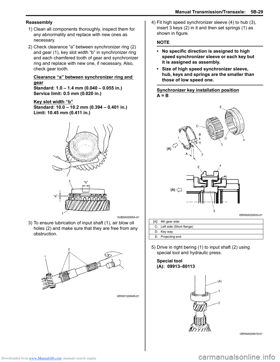
2) Check clearance “a” between synchronizer ring (2)
and gear (1), key slot width “b” in synchronizer ring
and each chamfered tooth of gear and synchronizer
ring and replace with new one, if necessary. Also,
check gear tooth.
Clearance “a” between synchronizer ring and
gear
Standard: 1.0 – 1.4 mm (0.040 – 0.055 in.)
Service limit: 0.5 mm (0.020 in.)
Key slot width “b”
Standard: 10.0 – 10.2 mm (0.394 – 0.401 in.)
Limit: 10.45 mm (0.411 in.)
3) To ensure lubrication of input shaft (1), air blow oil
holes (2) and make sure that they are free from any
obstruction.4) Fit high speed synchronizer sleeve (4) to hub (3),
insert 3 keys (2) in it and then set springs (1) as
shown in figure.
NOTE
• No specific direction is assigned to high
speed synchronizer sleeve or each key but
it is assigned as assembly.
• Size of high speed synchronizer sleeve,
hub, keys and springs are the smaller than
those of low speed one.
Synchronizer key installation position
A = B
5) Drive in right bering (1) to input shaft (2) using
special tool and hydraulic press.
Special tool
(A): 09913–80113
I5JB0A520054-01
I2RH01520049-01
[A]: 4th gear side
C: Left side (Short flange)
D: Key way
E: Projecting end
I5RW0A520033-01
I3RH0A520019-01
Page 844 of 1556

Downloaded from www.Manualslib.com manuals search engine 5B-32 Manual Transmission/Transaxle:
6) Disassemble synchronizer sleeve & hub assembly.
7) Take out 1st gear needle bearing from shaft.
8) In order to remove right bearing (1) from
countershaft, grind with a grinder (2) one part “a” of
right bearing (1) as illustrated till it becomes thin.
CAUTION!
Be careful not to grind too far not to damage
the shaft (3).
9) Break with a chisel (1) the thin ground right bearing
(2) and it can be removed.
Reassembly
1) Clean all components thoroughly, inspect them for
any abnormality and replace with new one as
necessary.
2) Check clearance “a” between synchronizer ring (2)
and gear (1), key slot width “b” in synchronizer ring
and each chamfered tooth of gear and synchronizer
ring and replace with new one, if necessary. Also,
check gear tooth.
Clearance “a” between synchronizer ring and
gear
Standard: 1.0 – 1.4 mm (0.040 – 0.055 in.)
Service limit: 0.5 mm (0.020 in.)
Key slot width “b”
Standard: 10.0 – 10.2 mm (0.394 – 0.401 in.)
Limit: 10.45 mm (0.411 in.)3) Put the synchronizer outer ring (1), inner ring (3) and
the cone (2) together and then measure the step
difference between the outer ring and the inner ring.
And also check each chamfered tooth of gear and
synchronizer ring and replace with new one, if
necessary. Also, check gear tooth.
Difference between synchronizer outer ring and
inner ring (2nd)
Standard “b”: 0.95 – 1.25 mm (0.036 – 0.048 in.)
Service limit “b”: 0.5 mm (0.019 in.)
4) To ensure lubrication of countershaft (1), air blow oil
holes (2) and make sure that they are free from any
obstruction.
3
1
2
“a”31
I5RW0A520035-01
1
2I5RW0A520036-01
I5JB0A520079-01
I2RH01520059-01
I2RH01520060-01
Page 847 of 1556

Downloaded from www.Manualslib.com manuals search engine Manual Transmission/Transaxle: 5B-35
Gear Shift Shaft ComponentsS6RW0D5206022
5th and Reverse Gear Shift Shafts Disassembly
and Reassembly
S6RW0D5206023
Disassembly
Disassemble component parts by using special tool and
hammer.
Special tool
: 09922–85811
Reassembly
Replace or correct parts as required and assemble
shafts making sure that component parts are in proper
order as shown in figure.
NOTE
Install 2 steel balls (3) in reverse gear shift
arm (1) without fail.
Gear Shift Shaft and Fork InspectionS6RW0D5206024
1) Using feeler gauge, check clearance between fork
(1) and sleeve (2) and replace those parts if it
exceeds limit of 1.0 mm (0.039 in.).
NOTE
For correct judgement of parts replacement,
carefully inspect contact portion of fork and
sleeve.
Clearance “a” between fork and sleeve
Service limit: 1.0 mm (0.039 in.)
2) Insert each gear shift shaft into case and check that
it moves smoothly. If it doesn’t, correct by using
oilstone, reamer or the like.
I5RW0A520041-01
1. Low speed gear shift shaft 4. 5th & reverse gear shift guide shaft 7. 5th & reverse gear shift yoke
2. High speed gear shift shaft 5. Reverse gear shift arm : 13 N⋅m (1.3 kgf-m, 9.5 lb-ft)
3. 5th & reverse gear shift shaft 6. Gear shift locating bolt
: Apply sealant 99000-31260 to bolt thread.
2. Spring 6. 5th & reverse gear shift yoke
4. Spring pin 7. 5th & reverse gear shift guide shaft
5. 5th & reverse gear shift shaft
I5RW0A520042-01
I2RH01520068-01
Page 851 of 1556

Downloaded from www.Manualslib.com manuals search engine Manual Transmission/Transaxle: 5B-39
Special Tools and Equipment
Recommended Service MaterialS6RW0D5208001
NOTE
Required service material is also described in the following.
“Gear Shift Control Lever and Cable Components”
“Gear Shift and Select Shaft Assembly Components”
“Manual Transaxle Assembly Components”
“Input Shaft and Countershaft Components”
“Gear Shift Shaft Components”
“Differential Components”
Special ToolS6RW0D5208002
Material SUZUKI recommended product or Specification Note
Grease SUZUKI Super Grease A P/No.: 99000–25011�) / �) / �)
Sealant SUZUKI Bond No.1217G P/No.: 99000–31260�) / �) / �) / �) / �) / �) / �) /
�) / �) / �)
Thread lock cement Thread Lock Cement Super 1322 P/No.: 99000–32110�) / �) / �) / �) / �)
09900–06107 09900–20607
Snap ring pliers (opening
type)Dial gauge
�) / �) / �) / �) / �) / �)�)
09900–20701 09913–50121
Magnetic stand Oil seal remover
�)�)
09913–65135 09913–70123
Bearing puller Bearing installing tool
�) / �)�) / �)
09913–75510 09913–75810
Bearing installer Bearing installer
�)�)
09913–75821 09913–75830
Bearing installer attachment Steering pinion bush
installer
�)�)
Page 862 of 1556

Downloaded from www.Manualslib.com manuals search engine 5C-9 Clutch:
Clutch Disc
Measure depth of rivet head depression, i.e. distance
between rivet head and facing surface.
If depression is found to have reached service limit at
any of rivet holes (2), replace clutch disc assembly (1).
Rivet head depth
Standard: 1.65 – 2.25 mm (0.06 – 0.09 in.)
Limit: 0.5 mm (0.02 in.)Clutch Cover
1) Check diaphragm spring (1) for abnormal wear or
damage.
2) Inspect pressure plate (2) for wear or heat spots.
3) If abnormality is found, replace clutch cover.
Do not disassemble it into diaphragm spring and
pressure plate.
Flywheel
Check surface contacting clutch disc for abnormal wear
or heat spots. Replace or repair as required.
Specifications
Tightening Torque SpecificationsS6RW0D5307001
NOTE
The specified tightening torque is also described in the following.
“Clutch Cover, Clutch Disc and Flywheel Components”
Reference:
For the tightening torque of fastener not specified in this section, refer to “Fasteners Information in Section 0A”.
I4RS0A530019-01
I3RM0A530015-01
Fastening partTightening torque
Note
N⋅mkgf-mlb-ft
Clutch master cylinder nut 13 1.3 9.5�)
Clutch operating cylinder assembly mounting
bolt10 1.0 7.5�)
Clutch fluid pipe flare nut 16 1.6 11.5�)
Flywheel bolt 70 7.0 51.0�)
Clutch cover bolt 23 2.3 17.0�)
Page 863 of 1556
Downloaded from www.Manualslib.com manuals search engine Clutch: 5C-10
Special Tools and Equipment
Recommended Service MaterialS6RW0D5308001
Special ToolS6RW0D5308002
Material SUZUKI recommended product or Specification Note
Grease SUZUKI Silicone Grease P/No.: 99000–25100�)
SUZUKI Super Grease I P/No.: 99000–25210�)
09921–26020 09923–36320
Bearing remover Clutch center guide (15 mm)
�)�)
09924–17810 09924–17811
Flywheel holder (drive plate
stopper)Flywheel holder
�) / �)�) / �)
09925–98210 09930–30104
Input shaft bearing installer Sliding shaft
�)�)