2006 SUZUKI SX4 accelera
[x] Cancel search: acceleraPage 980 of 1556

Downloaded from www.Manualslib.com manuals search engine 7B-40 Air Conditioning System: Automatic Type
HVAC Control DescriptionS6RW0D7221002
Temperature Control
HVAC control module calculates the target temperature
control door position based on signals from the
temperature selector, inside air temperature sensor,
outside air temperature sensor and sunload sensor and
controls the temperature control actuator so that the
current position of the temperature control door matches
its target position.
Fan Speed Control
HVAC control module calculates the target blower fan
speed based on signals from the temperature selector,
inside air temperature sensor, outside air temperature
sensor, ECT sensor and sunload sensor, compares it
with the current blower fan speed inputted from the
blower motor controller to control the current blower fan
speed to the target level.
Air Flow Outlet Control
HVAC control module calculates the target temperature
control door position based on signals from the
temperature selector, inside air temperature sensor,
outside air temperature sensor, ECT sensor and sunload
sensor. Using thus obtained target temperature control
door position, it further calculates the target air flow
control door position and controls the air flow control
actuator so that the current air flow control door position
becomes the target position.
Air Intake Position Control
HVAC control module determines the position of the air
intake control door based on signals from the
temperature selector, inside air temperature sensor,
outside air temperature sensor and sunload sensor and
selects any of the following positions by controlling the
position of the air intake control door.
• FRESH position (FRE)
• RECIRCULATION position (REC)
• MIX position (MIX)A/C Compressor Relay Control
HVAC control module outputs A/C switch ON signal to
ECM via BCM when the vehicle state satisfy conditions
described below.
• A/C switch is ON
• Evaporator temperature is higher than specified value
• Evaporator temperature sensor malfunction is not
detected
Communication of ECM and BCM is established by CAN
(Controller Area Network). (For more detail of CAN
communication, refer to “CAN Communication System
Description in Section 1A”).
ECM turns ON the A/C compressor relay when the
vehicle state satisfy conditions described below.
• A/C switch ON signal is inputted
• A/C refrigerant pressure is within specified range
• Engine speed is within specified range
• Engine coolant temperature is lower than specified
value
• Throttle opening is lower than specified value
• Vehicle is not in either state of starting or quick
acceleration
• ECT sensor malfunction is not detected
• A/C refrigerant pressure sensor malfunction is not
detected
Condenser Cooling Fan Relay Control
ECM turn ON the condenser cooling fan relay at the
same time when ECM turn ON the A/C compressor
relay.
Sub-Cool A/C System DescriptionS6RW0D7221003
Refer to “Sub-Cool A/C System Description”.
Page 1034 of 1556
Downloaded from www.Manualslib.com manuals search engine 8A-3 Seat Belts:
Seat Belt with ELR
The seat belt with emergency locking retractor (ELR) is
designed so that it locks immediately (to prevent the
webbing from being pulled out of the retractor any
further) when any of the following items is detected as
exceeding each set value;
• Speed at which the webbing is pulled out of the
retractor.
• Acceleration or deceleration of the vehicle speed.
• Inclination.
Seat Belt with A-ELR
The automatic and emergency locking retractor (A-ELR)
works as an Emergency Locking Retractor (ELR) till its
webbing is pulled all the way out and then on as an
Automatic Locking Retractor (ALR) till it is retracted fully.
ALR: Automatically locks when the webbing is pulled out
from the retractor and allowed to retract even a little.
Then the webbing can not be pulled out any further,
unless it is wound all the way back into the retractor,
which releases the lock and allows the webbing to be
pulled out.
Seat Belt with ELR and Pretensioner
The seat belt with ELR and a pretensioner has a
pretensioner mechanism which operates in linkage with
the air bag in addition to the described ELR.The pretensioner is incorporated in retractor and
controlled by SDM as one of air bag system
components. It will be activated at the same time as the
driver and passenger air bag module when an impact at
the front of vehicle exceeds the specified value.
When servicing seat belt (retractor) with pretensioner, be
sure to observe all WARNINGS and CAUTIONS and
“Precautions on Service and Diagnosis of Air Bag
System in Section 8B”.
CAUTION!
Do not reuse the seat belt pretensioner
(retractor) that has activated. Replace it with
a new seat belt and buckle together as a set.
For checking procedure of its activation,
refer to “Repair and Inspection Required after
Accident in Section 8B”.
Seat Belt Remainder
When driver’s seat belt is unfastened (under the
following conditions), seat belt reminder light inform that
driver’s seat belt is unfastened. Seat belt reminder light
located in combination meter located inside BCM
operate as follows:
• Seat belt reminder light comes on when driver’s seat
belt is unfastened while ignition key switch is at ON
position.
Diagnostic Information and Procedures
Repair and Inspection Required after AccidentS6RW0D8104001
After an accident, whether the seat belt pretensioner has been activated or not, be sure to perform checks and repairs
described on “Repair and Inspection Required after Accident in Section 8B”.
Page 1045 of 1556
Downloaded from www.Manualslib.com manuals search engine Air Bag System: 8B-6
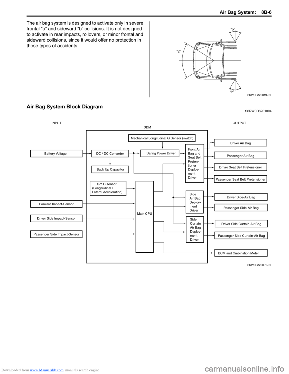
The air bag system is designed to activate only in severe
frontal “a” and sideward “b” collisions. It is not designed
to activate in rear impacts, rollovers, or minor frontal and
sideward collisions, since it would offer no protection in
those types of accidents.
Air Bag System Block DiagramS6RW0D8201004
I6RW0C820019-01
Battery Voltage
Forward Impact-Sensor
Driver Side Impact-Sensor
Passenger Side Impact-Sensor
DC / DC Converter
Back Up Capacitor
Safing Power Driver
Mechanical Longitudinal G Sensor (switch)
X-Y G sensor
(Longitudinal /
Lateral Acceleration)
Driver Side-Air Bag
Driver Side Curtain-Air Bag
Passenger Side Curtain-Air Bag
Passenger Side-Air Bag
Passenger Seat Belt Pretensioner
Driver Seat Belt Pretensioner
Passenger Air Bag
Driver Air Bag
INPUTOUTPUTSDM
Front Air
Bag and
Seat Belt
Preten-
tioner
Deploy-
ment
Driver
Side
Air Bag
Deploy-
ment
Driver
Side
Curtain
Air Bag
Deploy-
ment
Driver
Main CPU
BCM and Cmbination Meter
I6RW0C820001-01
Page 1046 of 1556
Downloaded from www.Manualslib.com manuals search engine 8B-7 Air Bag System:
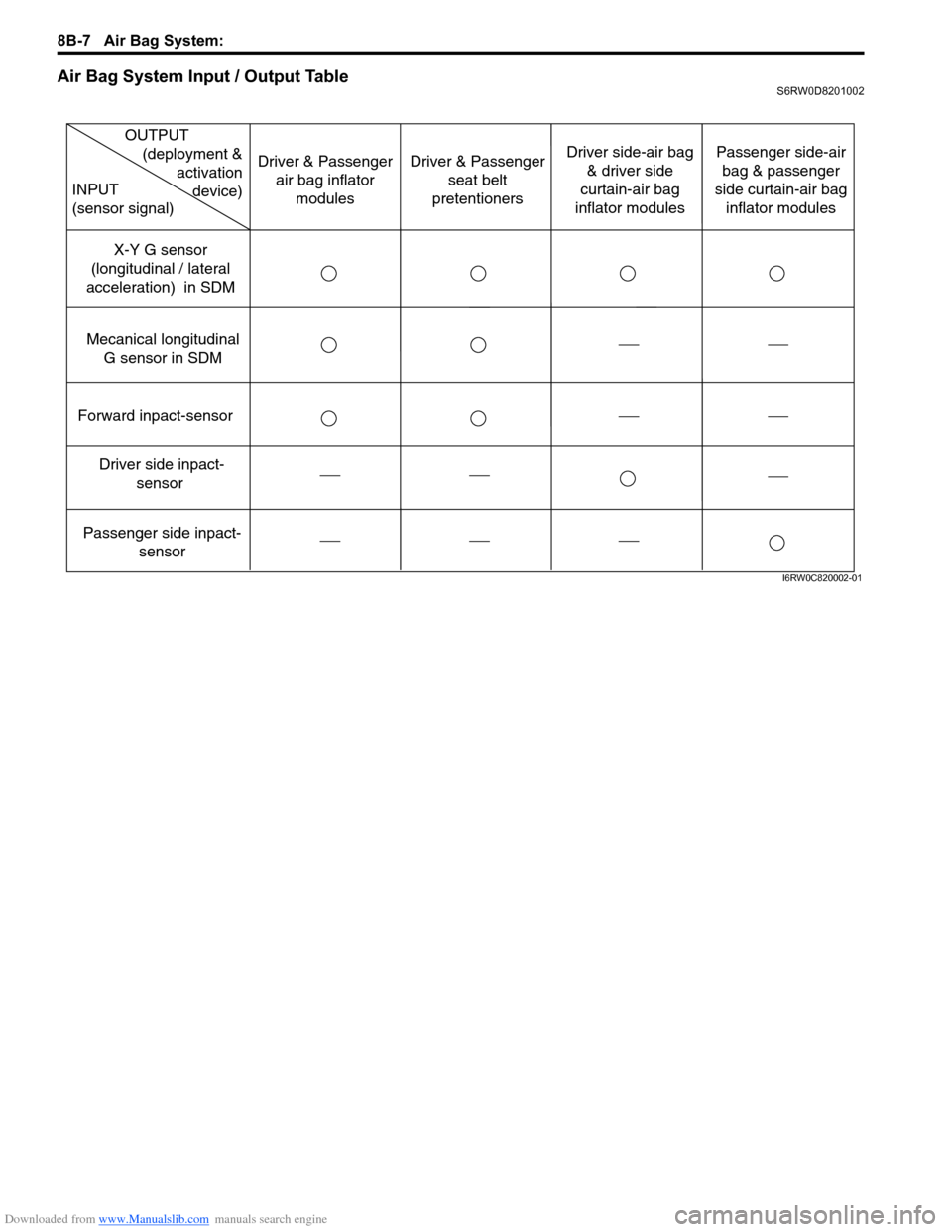
Air Bag System Input / Output TableS6RW0D8201002
Forward inpact-sensor
Driver side inpact-
sensor
Passenger side inpact-
sensor Mecanical longitudinal
G sensor in SDMX-Y G sensor
(longitudinal / lateral
acceleration) in SDM
OUTPUT
(deployment &
activation
device) INPUT
(sensor signal)
Driver & Passenger
air bag inflator
modulesDriver & Passenger
seat belt
pretentionersDriver side-air bag
& driver side
curtain-air bag
inflator modulesPassenger side-air
bag & passenger
side curtain-air bag
inflator modules
I6RW0C820002-01
Page 1048 of 1556
![SUZUKI SX4 2006 1.G Service Workshop Manual Downloaded from www.Manualslib.com manuals search engine 8B-9 Air Bag System:
Terminal arrangement of SDM (viewed from harness side)
[A]: Shorting bar 11. BCM 25. Driver seat belt pretensioner
[B]: C SUZUKI SX4 2006 1.G Service Workshop Manual Downloaded from www.Manualslib.com manuals search engine 8B-9 Air Bag System:
Terminal arrangement of SDM (viewed from harness side)
[A]: Shorting bar 11. BCM 25. Driver seat belt pretensioner
[B]: C](/manual-img/20/7612/w960_7612-1047.png)
Downloaded from www.Manualslib.com manuals search engine 8B-9 Air Bag System:
Terminal arrangement of SDM (viewed from harness side)
[A]: Shorting bar 11. BCM 25. Driver seat belt pretensioner
[B]: Connector 12. Combination meter 26. Passenger seat belt pretensioner
[C]: Junction block with BCM model 13. “AIR BAG” warning light27. Driver side-air bag (inflator) module (8-channel system)
[D]: Junction block without BCM model 14. Light driver 28. Passenger side-air bag (inflator) module (8-channel system)
1. Battery 15. SDM 29. Driver side curtain-air bag (inflator) module (8-channel
system)
2. Main fuse 16. To HVAC control module (auto A/C model) 30. Passenger side curtain-air bag (inflator) module (8-channel
system)
3. Fuse 17. Data link connector (DLC) 31. Safing power driver
4. Individual circuit fuse box No.1 18. Forward impact-sensor 32. X-Y-G (longitudinal / lateral acceleration)
5. “IGN” fuse 19. Driver side impact-sensor (8-channel
system)33. DC / DC converter
6. Ignition switch 20. Passenger side impact-sensor (8-channel
system)34. Mechanical longitudinal G sensor (switch)
7. Junction block assembly 21. Ground for air bag system 35. Back up capacitor
8. “DOME” fuse 22. Contact coil assembly
9. “METER” fuse 23. Driver air bag (inflator) module
10. “A/B” fuse 24. Passenger air bag (inflator) module
1
2 3 4 5 6 7 8 9 10 11 12 13 14 15 16 17 18 19 20 21 22 23 24 25 26
27 28 29 30 31 32 33 34 35 36 37 38 39 40 41 42 43 44 45 46 47 48 49 50 51
1
I7RW01822003-02
1. SDM Connector “L04”
Page 1186 of 1556
Downloaded from www.Manualslib.com manuals search engine 9A-19 Wiring Systems:
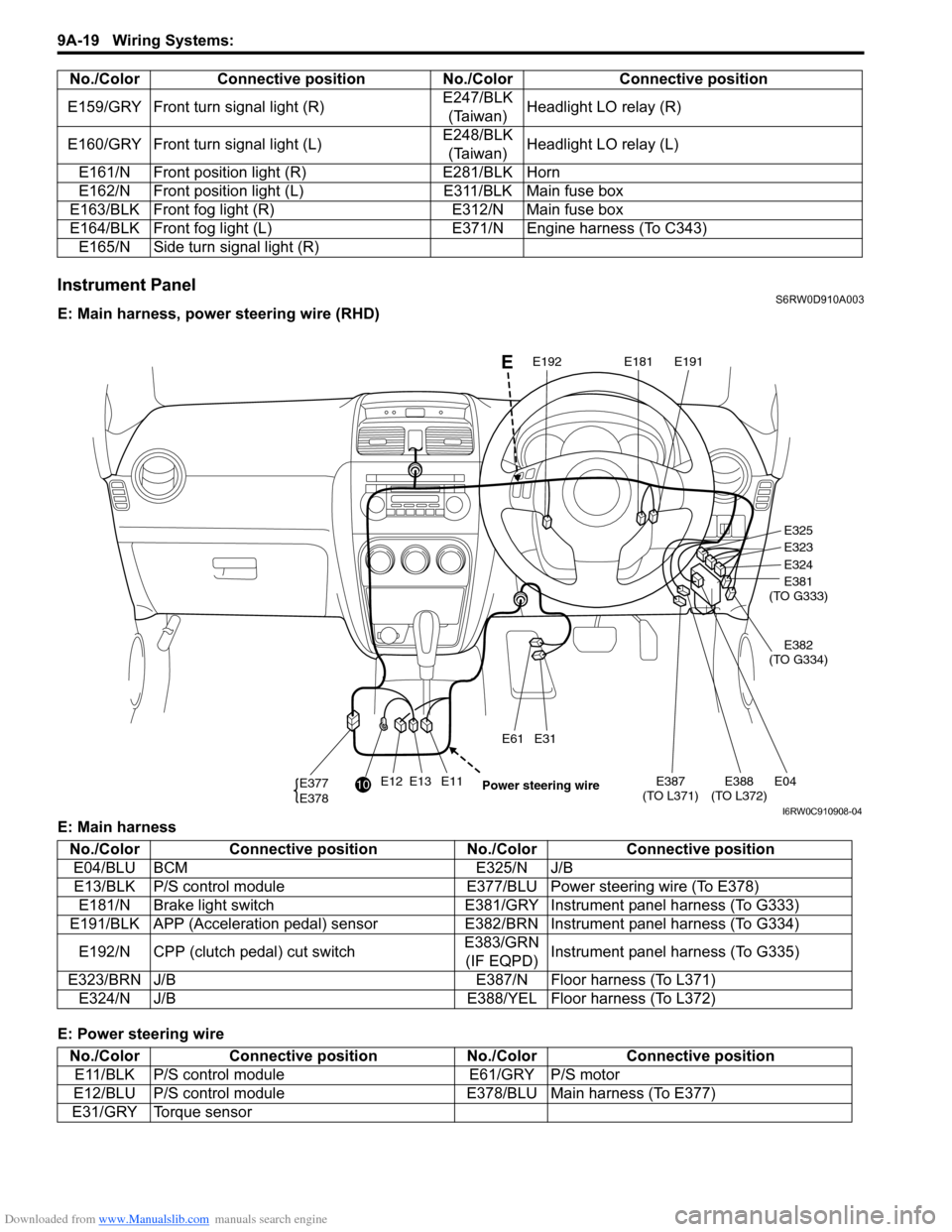
Instrument PanelS6RW0D910A003
E: Main harness, power steering wire (RHD)
E: Main harness
E: Power steering wireE159/GRY Front turn signal light (R)E247/BLK
(Taiwan)Headlight LO relay (R)
E160/GRY Front turn signal light (L)E248/BLK
(Taiwan)Headlight LO relay (L)
E161/N Front position light (R) E281/BLK Horn
E162/N Front position light (L) E311/BLK Main fuse box
E163/BLK Front fog light (R) E312/N Main fuse box
E164/BLK Front fog light (L) E371/N Engine harness (To C343)
E165/N Side turn signal light (R) No./Color Connective position No./Color Connective position
E12E13E11E387
(TO L371)E04E388
(TO L372)
E31E61
E377
E378
E325
E323
E324
E381
(TO G333)
E382
(TO G334)
E191E181E192
10
Power steering wire
E
I6RW0C910908-04
No./Color Connective position No./Color Connective position
E04/BLU BCM E325/N J/B
E13/BLK P/S control module E377/BLU Power steering wire (To E378)
E181/N Brake light switch E381/GRY Instrument panel harness (To G333)
E191/BLK APP (Acceleration pedal) sensor E382/BRN Instrument panel harness (To G334)
E192/N CPP (clutch pedal) cut switchE383/GRN
(IF EQPD)Instrument panel harness (To G335)
E323/BRN J/B E387/N Floor harness (To L371)
E324/N J/B E388/YEL Floor harness (To L372)
No./Color Connective position No./Color Connective position
E11/BLK P/S control module E61/GRY P/S motor
E12/BLU P/S control module E378/BLU Main harness (To E377)
E31/GRY Torque sensor
Page 1187 of 1556
Downloaded from www.Manualslib.com manuals search engine Wiring Systems: 9A-20
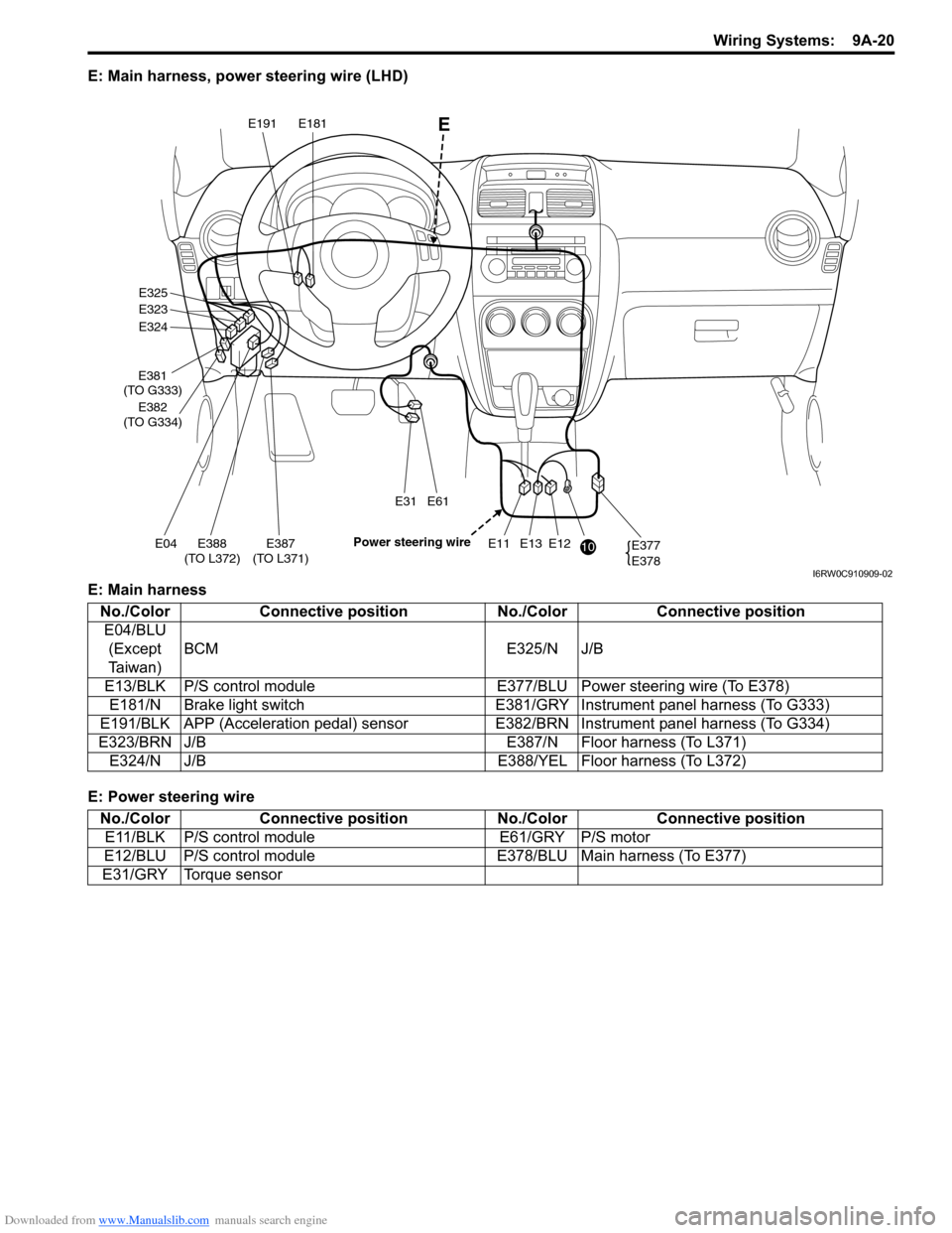
E: Main harness, power steering wire (LHD)
E: Main harness
E: Power steering wire
E12E13E11E387
(TO L371)E04E388
(TO L372)
E31E61
E377
E378
E325
E323
E324
E381
(TO G333)
E382
(TO G334)
E191E181
10 Power steering wire
E
I6RW0C910909-02
No./Color Connective position No./Color Connective position
E04/BLU
(Except
Taiwan)BCM E325/N J/B
E13/BLK P/S control module E377/BLU Power steering wire (To E378)
E181/N Brake light switch E381/GRY Instrument panel harness (To G333)
E191/BLK APP (Acceleration pedal) sensor E382/BRN Instrument panel harness (To G334)
E323/BRN J/B E387/N Floor harness (To L371)
E324/N J/B E388/YEL Floor harness (To L372)
No./Color Connective position No./Color Connective position
E11/BLK P/S control module E61/GRY P/S motor
E12/BLU P/S control module E378/BLU Main harness (To E377)
E31/GRY Torque sensor
Page 1355 of 1556
Downloaded from www.Manualslib.com manuals search engine Instrumentation / Driver Info. / Horn: 9C-3
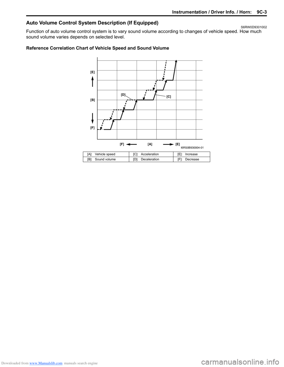
Auto Volume Control System Description (If Equipped)S6RW0D9301002
Function of auto volume control system is to vary sound volume according to changes of vehicle speed. How much
sound volume varies depends on selected level.
Reference Correlation Chart of Vehicle Speed and Sound Volume
[A]: Vehicle speed [C]: Acceleration [E]: Increase
[B]: Sound volume [D]: Deceleration [F]: Decrease
[A] [E] [F] [B] [E]
[F][C]
[D]
I6RS0B930004-01