Page 1126 of 1556

Downloaded from www.Manualslib.com manuals search engine 8B-87 Air Bag System:
Contact Coil Cable and Its Circuit CheckS6RW0D8204050
Troubleshooting
Step Action Yes No
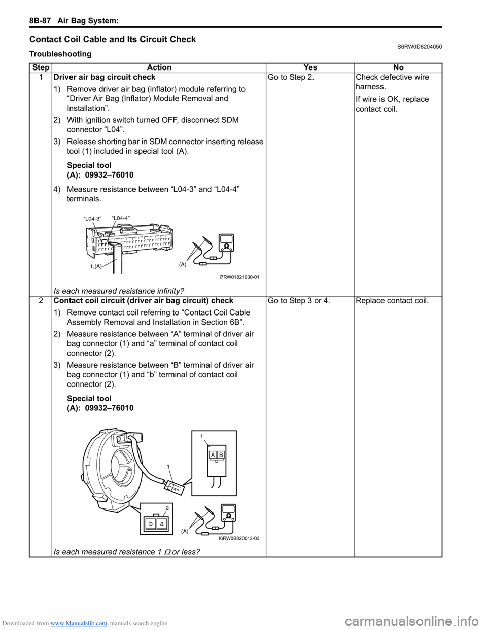
1Driver air bag circuit check
1) Remove driver air bag (inflator) module referring to
“Driver Air Bag (Inflator) Module Removal and
Installation”.
2) With ignition switch turned OFF, disconnect SDM
connector “L04”.
3) Release shorting bar in SDM connector inserting release
tool (1) included in special tool (A).
Special tool
(A): 09932–76010
4) Measure resistance between “L04-3” and “L04-4”
terminals.
Is each measured resistance infinity?Go to Step 2. Check defective wire
harness.
If wire is OK, replace
contact coil.
2Contact coil circuit (driver air bag circuit) check
1) Remove contact coil referring to “Contact Coil Cable
Assembly Removal and Installation in Section 6B”.
2) Measure resistance between “A” terminal of driver air
bag connector (1) and “a” terminal of contact coil
connector (2).
3) Measure resistance between “B” terminal of driver air
bag connector (1) and “b” terminal of contact coil
connector (2).
Special tool
(A): 09932–76010
Is each measured resistance 1
Ω or less?Go to Step 3 or 4. Replace contact coil.
“L04-4”
“L04-3”
1,(A)(A)
I7RW01821030-01
1
1
AB
(A)ba
2
I6RW0B820013-03
Page 1168 of 1556

Downloaded from www.Manualslib.com manuals search engine 9A-1 Wiring Systems:
Body, Cab and Accessories
Wiring Systems
Precautions
Cautions in Body Electrical System ServicingS6RW0D9100001
When servicing the electric systems, observe the cautions described in “Air Bag Warning in Section 00” to protect
electrical parts and to prevent a fire.
General Description
AbbreviationsS6RW0D9101001
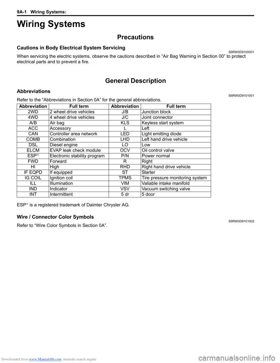
Refer to the “Abbreviations in Section 0A” for the general abbreviations.
ESP
® is a registered trademark of Daimler Chrysler AG.
Wire / Connector Color SymbolsS6RW0D9101002
Refer to “Wire Color Symbols in Section 0A”. Abbreviation Full term Abbreviation Full term
2WD 2 wheel drive vehicles J/B Junction block
4WD 4 wheel drive vehicles J/C Joint connector
A/B Air bag KLS Keyless start system
ACC Accessory L Left
CAN Controller area network LED Light emitting diode
COMB Combination LHD Left hand drive vehicle
DSL Diesel engine LO Low
ELCM EVAP leak check module OCV Oil control valve
ESP
®Electronic stability program P/N Power normal
FWD Forward R Right
HI High RHD Right hand drive vehicle
IF EQPD If equipped ST Starter
IG COIL Ignition coil TPMS Tire pressure monitoring system
ILL Illumination VIM Valiable intake manifold
IND Indicator VSV Vacuum switching valve
INT Intermittent 5 dr 5 door
Page 1227 of 1556
Downloaded from www.Manualslib.com manuals search engine Wiring Systems: 9A-60
A-3 Ignition System Circuit Diagram (M15A engine, M16A engine)S6RW0D910E004
15A
20E371
C343
2
C1011
3
IG COIL
#1
C102
BLK
BLK/WHTGRN/YEL
BLK/WHT
J/B
ECM
GYGW
20IG COIL
BLK
BLK
IG COIL
#2
E3255
3
GRN/WHT
1
3
2
C015 6
Weld
splice
C312
BLK/WHT
BLK/WHT
I6RW0C910935-01
Page 1228 of 1556
Downloaded from www.Manualslib.com manuals search engine 9A-61 Wiring Systems:
A-3 Ignition System Circuit Diagram (J20A engine)S6RW0D910E039
15A
20E371
C343
2
C1013
1
IG
COIL
#1
C102
BLK
BLK/WHTBLK/WHTBLK/WHTGRN/YEL
BLK/WHT
J/B
ECM
GYGW
20IG COIL
BLKBLK
BLKBLKBLK
IG
COIL
#2
E3255
3
GRN/WHT
4
3
1
2
C0120 21
Weld
splice
C312
BLK/WHT
GB
GRN/BLK
19
G
GRN
18
C103
IG
COIL
#3
3
1
2C104
IG
COIL
#4
3
1
2
BLK/WHT
I6RW0C910A14-01
Page 1504 of 1556

Downloaded from www.Manualslib.com manuals search engine 10C-2 Immobilizer Control System:
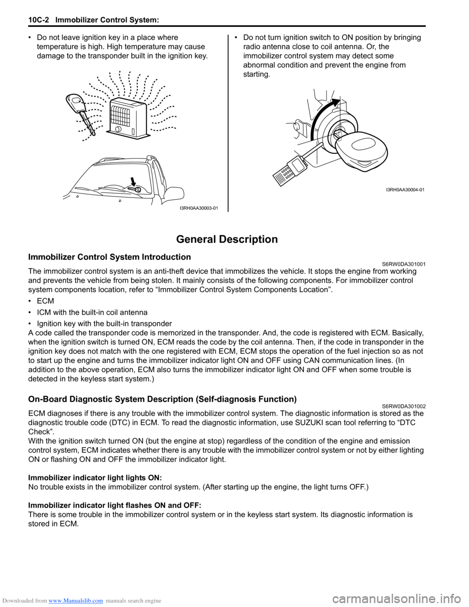
• Do not leave ignition key in a place where
temperature is high. High temperature may cause
damage to the transponder built in the ignition key.• Do not turn ignition switch to ON position by bringing
radio antenna close to coil antenna. Or, the
immobilizer control system may detect some
abnormal condition and prevent the engine from
starting.
General Description
Immobilizer Control System IntroductionS6RW0DA301001
The immobilizer control system is an anti-theft device that immobilizes the vehicle. It stops the engine from working
and prevents the vehicle from being stolen. It mainly consists of the following components. For immobilizer control
system components location, refer to “Immobilizer Control System Components Location”.
•ECM
• ICM with the built-in coil antenna
• Ignition key with the built-in transponder
A code called the transponder code is memorized in the transponder. And, the code is registered with ECM. Basically,
when the ignition switch is turned ON, ECM reads the code by the coil antenna. Then, if the code in transponder in the
ignition key does not match with the one registered with ECM, ECM stops the operation of the fuel injection so as not
to start up the engine and turns the immobilizer indicator light ON and OFF using CAN communication lines. (In
addition to the above operation, ECM also turns the immobilizer indicator light ON and OFF when some trouble is
detected in the keyless start system.)
On-Board Diagnostic System Description (Self-diagnosis Function)S6RW0DA301002
ECM diagnoses if there is any trouble with the immobilizer control system. The diagnostic information is stored as the
diagnostic trouble code (DTC) in ECM. To read the diagnostic information, use SUZUKI scan tool referring to “DTC
Check”.
With the ignition switch turned ON (but the engine at stop) regardless of the condition of the engine and emission
control system, ECM indicates whether there is any trouble with the immobilizer control system or not by either lighting
ON or flashing ON and OFF the immobilizer indicator light.
Immobilizer indicator light lights ON:
No trouble exists in the immobilizer control system. (After starting up the engine, the light turns OFF.)
Immobilizer indicator light flashes ON and OFF:
There is some trouble in the immobilizer control system or in the keyless start system. Its diagnostic information is
stored in ECM.
I3RH0AA30003-01
I3RH0AA30004-01