2006 SUZUKI SX4 Can line
[x] Cancel search: Can linePage 922 of 1556

Downloaded from www.Manualslib.com manuals search engine 6C-42 Power Assisted Steering System:
5) Turn ON ignition switch without engine running and
select scan tool “Data List” mode due to checking
“Sensor (Main) Torque” and “Sensor (Sub) Torque”
displayed on scan tool when steering wheel turned
left and right (if used).
6) Check that characteristic of torque sensor (main and
sub) output voltage or scan tool data and steering
force is as following graph when steering wheel is
turned left and right. If sensor voltage or scan tool
data is out of specified value or does not vary linearly
as the following graph, check EPS control module
and its circuit referring to “Inspection of P/S Control
Module and Its Circuits”.
If they are OK, replace steering gear case assembly.P/S Motor and Its Circuit InspectionS6RW0D6306013
1) Check motor circuit referring to Step 2 to 3 of “DTC
C1141 / C1142 / C1143 / C1145: Motor Circuit
Failure”. If check result is not satisfactory, repair
motor circuit.
2) Disconnect motor connector from steering gear case
assembly with ignition switch turned OFF.
3) Check for resistance between terminals of motor
connector.
If check result is not as specified, check P/S motor
harness for continuity. If it is OK, replace steering
gear case assembly.
Motor circuit resistance
4) Check for insulation between each terminal of motor
connector and body ground.
If check result is not as specified, check P/S motor
harness for insulation. If it is OK, replace steering
gear case assembly.
Motor circuit resistance
5) Hoist vehicle
6) Check that steering wheel turns to left and right
smoothly. If steering wheel does not turn smoothly,
inspect and repair defective steering and suspension
parts.
7) Connect “E12” connector with ignition switch turned
OFF.
[A]: Main sensor
[B]: Sub sensor
[C]: Steering force at left turn
[D]: Steering force at right turn
[E]: Steering wheel at free
[F]: “Sensor (Main) Torque” in “Data List” displayed on scan tool
[G]: “Sensor (Sub) Torque” in “Data List” displayed on scan tool
0
[E][N.m]
MAX
MAX [D] [C]
[E][D] [C]
2.33 - 2.68[V] [F]
[G] [A]
[B]
66
1.65 - 1.9
(1.0 - 1.3)3.0 - 3.4 (3.7 - 4.0)
0 5
2.33 - 2.681.65 - 1.9
(1.0 - 1.3)3.0 - 3.4 (3.7 - 4.0)
0 5
0
[N.m]
MAX
MAX
[V]
6 11.76 11.7611.76 11.766
0 11.5
-12.00 -12.0
11.5
I7RW01632011-02
“E12-1” and “E12-2” (For motor) Approx. 1 Ω
Each terminal and body ground No continuity
[A]: Motor connector “E12” (viewed from harness side)
12
[A]
I6RW0C630012-02
Page 981 of 1556

Downloaded from www.Manualslib.com manuals search engine Air Conditioning System: Automatic Type 7B-41
On-Board Diagnostic System DescriptionS6RW0D7221004
NOTE
The diagnostic information as diagnostic
trouble code (DTC) can be known by using
SUZUKI scan tool. For further details, refer to
“DTC Check”.
HVAC control module detects malfunctions, which may
occur in the following area.
• Inside air temperature sensor
• Evaporator temperature sensor
• Sunload sensor
• Temperature control actuator
• Air flow control actuator
• Temperature selector of HVAC control module
• Air flow selector of HVAC control module
• Blower speed selector of HVAC control module
• Back-up power supply circuit of HAVC control module
• Serial communication line between BCM and HVAC
control module• Received data from BCM as follows
– Outside air temperature sensor signal
– ECT sensor signal
– A/C refrigerant pressure sensor signal
– VSS signal
– Engine type signal
– Combination meter spec signal
– CAN communication circuit failure signal
When HVAC control module detects malfunction, the “A/
C” indicator light (1) flashes to warn and the diagnostic
trouble code (DTC) is stored in the memory of the
module. When diagnosing trouble, the DTC can be
checked according to “DTC Check”.
Schematic and Routing Diagram
A/C System Air Flow DiagramS6RW0D7222001
Refer to “A/C System Air Flow Diagram”.
1
I5RW0A722002-01
Page 1016 of 1556
Downloaded from www.Manualslib.com manuals search engine 7B-76 Air Conditioning System: Automatic Type
Inspection of HVAC Control Module and Its CircuitS6RW0D7224029
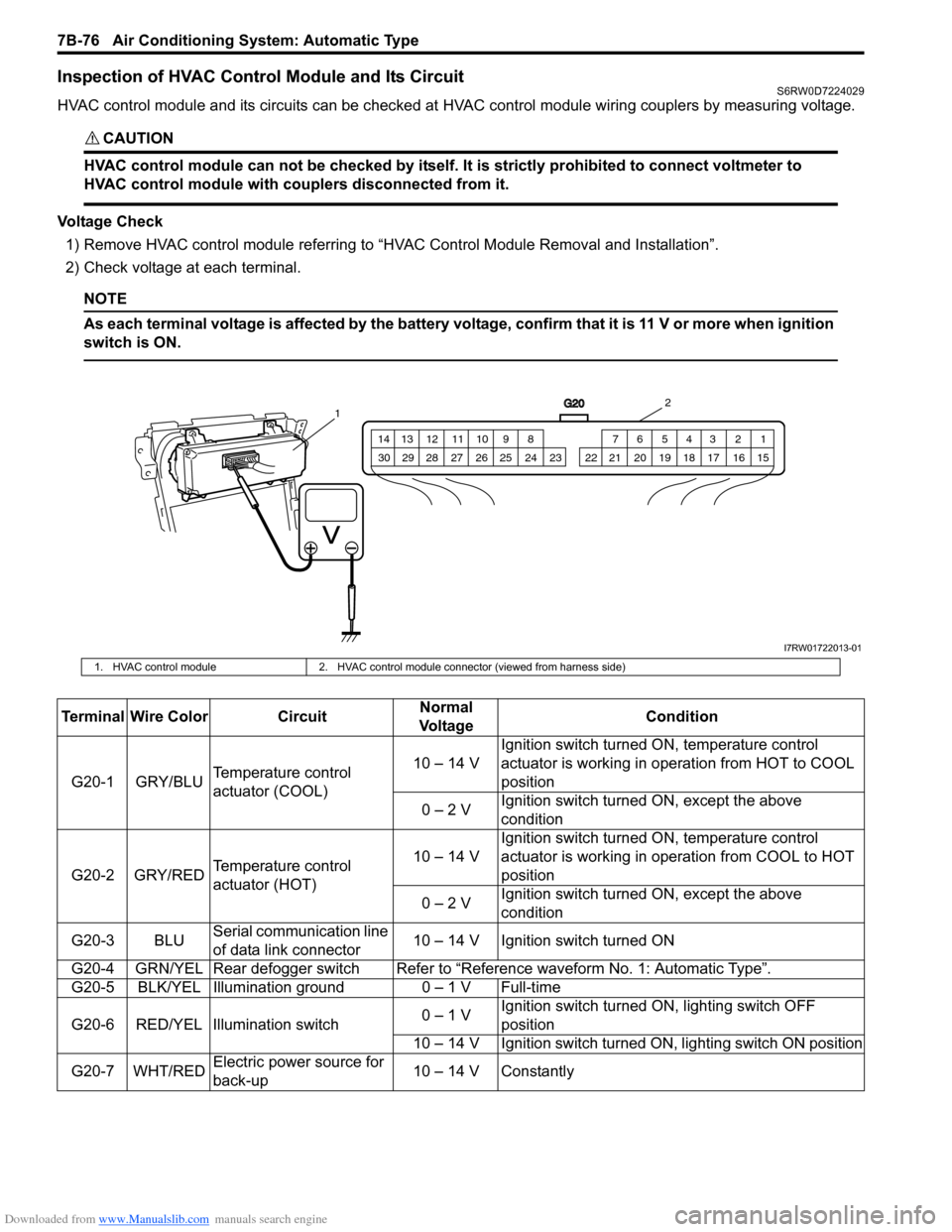
HVAC control module and its circuits can be checked at HVAC control module wiring couplers by measuring voltage.
CAUTION!
HVAC control module can not be checked by itself. It is strictly prohibited to connect voltmeter to
HVAC control module with couplers disconnected from it.
Voltage Check
1) Remove HVAC control module referring to “HVAC Control Module Removal and Installation”.
2) Check voltage at each terminal.
NOTE
As each terminal voltage is affected by the battery voltage, confirm that it is 11 V or more when ignition
switch is ON.
G20
1 2 3 4 5 6 7 8 9 10 11 12 13 14
15 16 17 18 19 20 21 24 23 22 25 26 27 28 29 30
12
I7RW01722013-01
1. HVAC control module 2. HVAC control module connector (viewed from harness side)
Terminal Wire Color CircuitNormal
Vo l ta g eCondition
G20-1 GRY/BLUTemperature control
actuator (COOL)10 – 14 VIgnition switch turned ON, temperature control
actuator is working in operation from HOT to COOL
position
0 – 2 VIgnition switch turned ON, except the above
condition
G20-2 GRY/REDTemperature control
actuator (HOT)10 – 14 VIgnition switch turned ON, temperature control
actuator is working in operation from COOL to HOT
position
0 – 2 VIgnition switch turned ON, except the above
condition
G20-3 BLUSerial communication line
of data link connector10 – 14 V Ignition switch turned ON
G20-4 GRN/YEL Rear defogger switchRefer to “Reference waveform No. 1: Automatic Type”.
G20-5 BLK/YEL Illumination ground 0 – 1 V Full-time
G20-6 RED/YEL Illumination switch0 – 1 VIgnition switch turned ON, lighting switch OFF
position
10 – 14 V Ignition switch turned ON, lighting switch ON position
G20-7 WHT/REDElectric power source for
back-up10 – 14 V Constantly
Page 1057 of 1556
Downloaded from www.Manualslib.com manuals search engine Air Bag System: 8B-18
DTC CheckS6RW0D8204004
1) Turn ignition switch to OFF position.
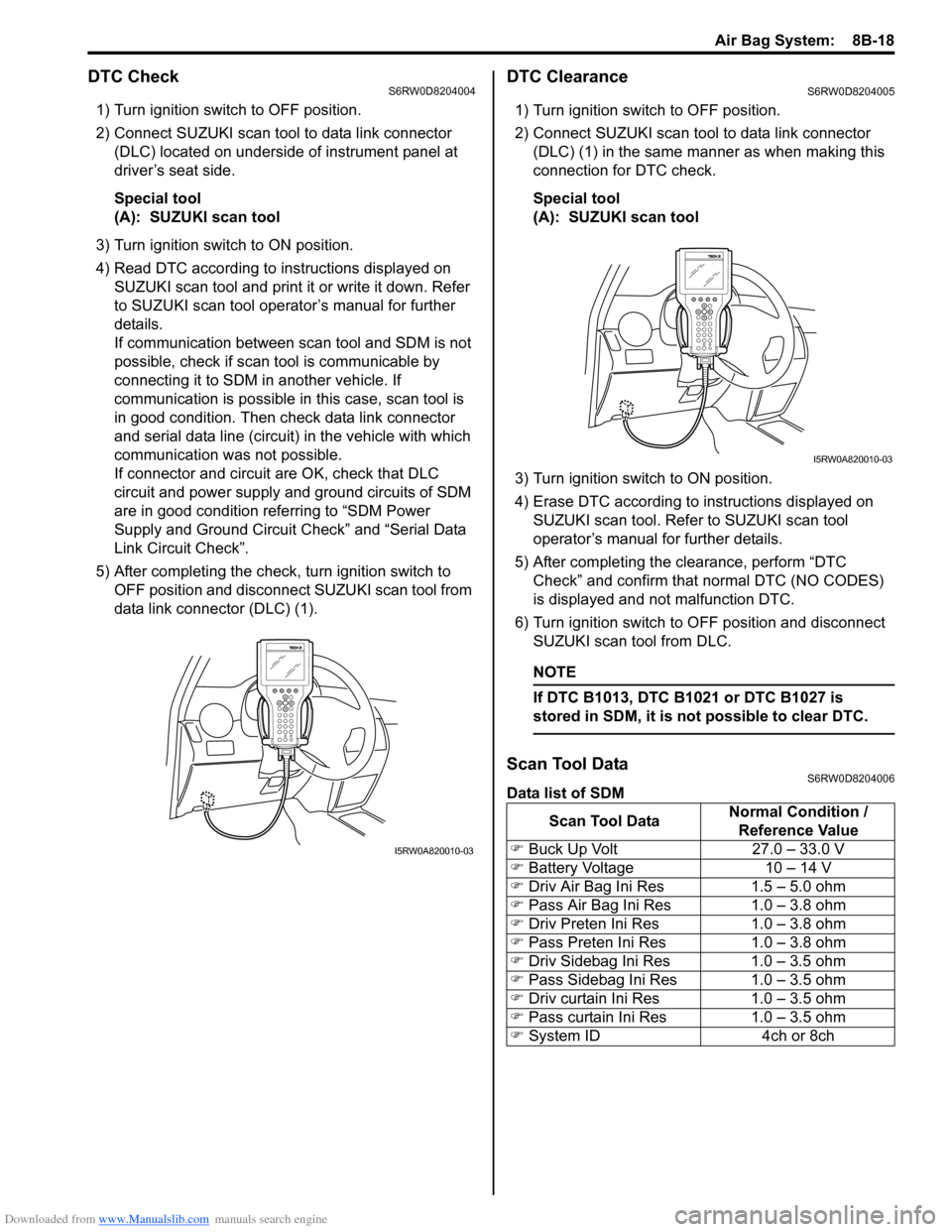
2) Connect SUZUKI scan tool to data link connector
(DLC) located on underside of instrument panel at
driver’s seat side.
Special tool
(A): SUZUKI scan tool
3) Turn ignition switch to ON position.
4) Read DTC according to instructions displayed on
SUZUKI scan tool and print it or write it down. Refer
to SUZUKI scan tool operator’s manual for further
details.
If communication between scan tool and SDM is not
possible, check if scan tool is communicable by
connecting it to SDM in another vehicle. If
communication is possible in this case, scan tool is
in good condition. Then check data link connector
and serial data line (circuit) in the vehicle with which
communication was not possible.
If connector and circuit are OK, check that DLC
circuit and power supply and ground circuits of SDM
are in good condition referring to “SDM Power
Supply and Ground Circuit Check” and “Serial Data
Link Circuit Check”.
5) After completing the check, turn ignition switch to
OFF position and disconnect SUZUKI scan tool from
data link connector (DLC) (1).
DTC ClearanceS6RW0D8204005
1) Turn ignition switch to OFF position.
2) Connect SUZUKI scan tool to data link connector
(DLC) (1) in the same manner as when making this
connection for DTC check.
Special tool
(A): SUZUKI scan tool
3) Turn ignition switch to ON position.
4) Erase DTC according to instructions displayed on
SUZUKI scan tool. Refer to SUZUKI scan tool
operator’s manual for further details.
5) After completing the clearance, perform “DTC
Check” and confirm that normal DTC (NO CODES)
is displayed and not malfunction DTC.
6) Turn ignition switch to OFF position and disconnect
SUZUKI scan tool from DLC.
NOTE
If DTC B1013, DTC B1021 or DTC B1027 is
stored in SDM, it is not possible to clear DTC.
Scan Tool DataS6RW0D8204006
Data list of SDM
I5RW0A820010-03
Scan Tool DataNormal Condition /
Reference Value
�) Buck Up Volt 27.0 – 33.0 V
�) Battery Voltage 10 – 14 V
�) Driv Air Bag Ini Res 1.5 – 5.0 ohm
�) Pass Air Bag Ini Res 1.0 – 3.8 ohm
�) Driv Preten Ini Res 1.0 – 3.8 ohm
�) Pass Preten Ini Res 1.0 – 3.8 ohm
�) Driv Sidebag Ini Res 1.0 – 3.5 ohm
�) Pass Sidebag Ini Res 1.0 – 3.5 ohm
�) Driv curtain Ini Res 1.0 – 3.5 ohm
�) Pass curtain Ini Res 1.0 – 3.5 ohm
�) System ID 4ch or 8ch
I5RW0A820010-03
Page 1346 of 1556
Downloaded from www.Manualslib.com manuals search engine 9B-27 Lighting Systems:
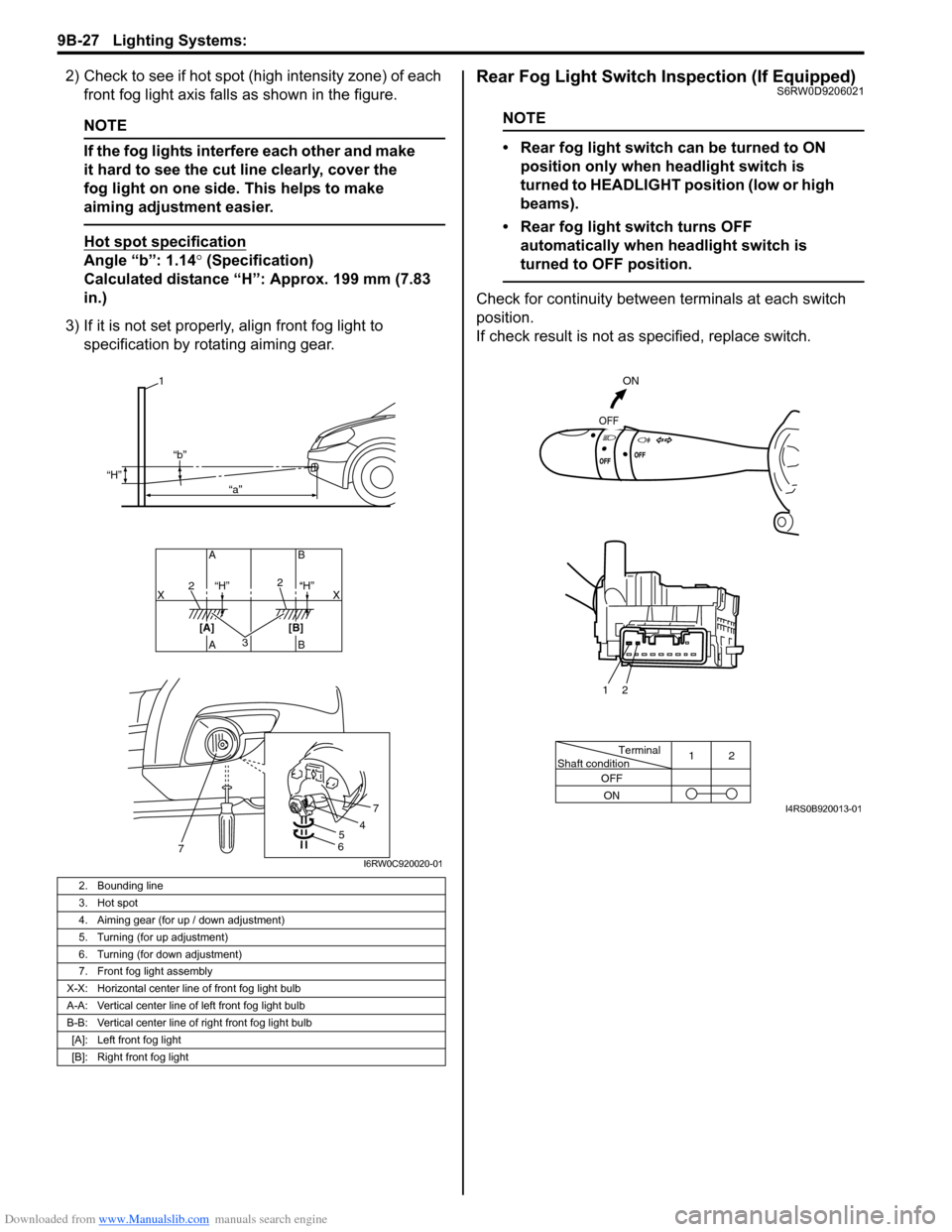
2) Check to see if hot spot (high intensity zone) of each
front fog light axis falls as shown in the figure.
NOTE
If the fog lights interfere each other and make
it hard to see the cut line clearly, cover the
fog light on one side. This helps to make
aiming adjustment easier.
Hot spot specification
Angle “b”: 1.14° (Specification)
Calculated distance “H”: Approx. 199 mm (7.83
in.)
3) If it is not set properly, align front fog light to
specification by rotating aiming gear.
Rear Fog Light Switch Inspection (If Equipped)S6RW0D9206021
NOTE
• Rear fog light switch can be turned to ON
position only when headlight switch is
turned to HEADLIGHT position (low or high
beams).
• Rear fog light switch turns OFF
automatically when headlight switch is
turned to OFF position.
Check for continuity between terminals at each switch
position.
If check result is not as specified, replace switch.
2. Bounding line
3. Hot spot
4. Aiming gear (for up / down adjustment)
5. Turning (for up adjustment)
6. Turning (for down adjustment)
7. Front fog light assembly
X-X: Horizontal center line of front fog light bulb
A-A: Vertical center line of left front fog light bulb
B-B: Vertical center line of right front fog light bulb
[A]: Left front fog light
[B]: Right front fog light
32
2
AB AB
[A] [B]X X
1
“H”
“H” “H” “b”
“a”
54
7
67I6RW0C920020-01
Terminal
Shaft condition12
OFF
ON
ON
OFF
2 1
I4RS0B920013-01
Page 1357 of 1556
Downloaded from www.Manualslib.com manuals search engine Instrumentation / Driver Info. / Horn: 9C-5
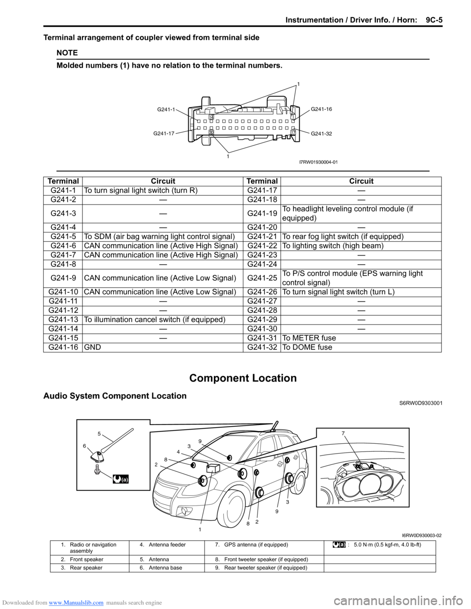
Terminal arrangement of coupler viewed from terminal side
NOTE
Molded numbers (1) have no relation to the terminal numbers.
Component Location
Audio System Component LocationS6RW0D9303001
Terminal Circuit Terminal Circuit
G241-1 To turn signal light switch (turn R) G241-17 —
G241-2 — G241-18 —
G241-3 — G241-19To headlight leveling control module (if
equipped)
G241-4 — G241-20 —
G241-5 To SDM (air bag warning light control signal) G241-21 To rear fog light switch (if equipped)
G241-6 CAN communication line (Active High Signal) G241-22 To lighting switch (high beam)
G241-7 CAN communication line (Active High Signal) G241-23 —
G241-8 — G241-24 —
G241-9 CAN communication line (Active Low Signal) G241-25To P/S control module (EPS warning light
control signal)
G241-10 CAN communication line (Active Low Signal) G241-26 To turn signal light switch (turn L)
G241-11 — G241-27 —
G241-12 — G241-28 —
G241-13 To illumination cancel switch (if equipped) G241-29 —
G241-14 — G241-30 —
G241-15 — G241-31 To METER fuse
G241-16 GND G241-32 To DOME fuse
G241-1G241-16
G241-32 G241-17
11I7RW01930004-01
3
2
3
2
1
4
8
8
9
96
5
(a)
7
I6RW0D930003-02
1. Radio or navigation
assembly4. Antenna feeder 7. GPS antenna (if equipped) : 5.0 N⋅m (0.5 kgf-m, 4.0 lb-ft)
2. Front speaker 5. Antenna 8. Front tweeter speaker (if equipped)
3. Rear speaker 6. Antenna base 9. Rear tweeter speaker (if equipped)
Page 1472 of 1556
Downloaded from www.Manualslib.com manuals search engine 10-ii Table of Contents
Immobilizer Indicator Light Remains ON after
Engine Start ..................................................10C-10
DTC P1614: Transponder Response Error .....10C-10
DTC P1615: Steering Lock Unit
Communication Error ....................................10C-11
DTC P1616: Unregistered Keyless Start
Control Module ..............................................10C-12
DTC P1618: Keyless Start Control Module
CAN Communication Error............................10C-13
DTC P1621: Immobilizer Communication
Line Error ......................................................10C-13
DTC P1622: EEPROM Reading / Writing
Error ..............................................................10C-14
DTC P1623: Unregistered Transponder .........10C-14
DTC P1625: Immobilizer Antenna Error..........10C-15
DTC P1636: Immobilizer Information
Registration Failure .......................................10C-15
DTC P1638: Immobilizer Information
Mismatched ...................................................10C-16
Inspection of ICM and Its Circuit .....................10C-17
Repair Instructions ..........................................10C-19
ICM Removal and Installation .........................10C-19
Registration of the Ignition Key .......................10C-19
Procedure after ECM Replacement ................10C-19
Special Tools and Equipment .........................10C-20
Special Tool ....................................................10C-20
Keyless Start System .............................10E-1
General Description ........................................... 10E-1
Keyless Start System Description ..................... 10E-1
Parts and Functions .......................................... 10E-2
Keyless Engine Start Function .......................... 10E-3
Door Lock Function of Keyless Start System .... 10E-4
Operation Area of Remote Controller................ 10E-5
Alarm Function .................................................. 10E-6
CAN Communication System Description......... 10E-6
Schematic and Routing Diagram ...................... 10E-7
Keyless Start System Electric Wiring Circuit
Diagram .......................................................... 10E-7
Diagnostic Information and Procedures .......... 10E-8
Precautions in Diagnosing Troubles ................. 10E-8
Self-Diagnosis Function .................................... 10E-8
Keyless Start System Diagnosis Introduction ... 10E-8
Keyless Start System Check ............................. 10E-9
Customer Questionnaire (Example) ................ 10E-10Key Indicator Light Check ............................... 10E-10
DTC Check...................................................... 10E-11
DTC Table ....................................................... 10E-12
DTC Clearance ............................................... 10E-12
Keyless Start System Symptom Diagnosis ..... 10E-13
Keyless Start System Operation Inspection .... 10E-14
Door Lock Operation (Keyless Start System) . 10E-14
Inspection of Keyless Start Control Module
and Its Circuits .............................................. 10E-14
No DTC Detection After Performing DTC
Check ............................................................ 10E-20
Key Indicator Light Circuit Check (Key
Indicator Light Doesn’t Light when Ignition
Knob Switch is Pushed) ................................ 10E-21
Keyless Start Control Module Power and
Ground Circuit Check .................................... 10E-23
DTC No. 11: Communication Error with
Steering Lock Unit ......................................... 10E-24
DTC No. 13 / No. 14: Release Signal Error
from Steering Lock Unit / Steering Lock Unit
Malfunction .................................................... 10E-25
DTC No. 21 / No. 22: Internal Error of Keyless
Start Control Module (EEPROM Reading
Error) / (EEPROM Writing Error) ................... 10E-25
DTC No. 31: Lost Communication with BCM .. 10E-26
DTC No. 33: Control Module Communication
Bus Off .......................................................... 10E-26
DTC No. 51 / No. 52 / No. 53: Driver Side /
Passenger Side / Rear End Door Request
Switch Failure................................................ 10E-26
Repair Instructions .......................................... 10E-27
Antennas and Request Switches Removal
and Installation .............................................. 10E-27
Front Door (Driver and Passenger Side), Rear
End Door Request Switch Inspection............ 10E-28
Steering Lock Unit Removal and Installation .. 10E-28
Steering Lock Unit Inspection ......................... 10E-28
Front Door Lock Switch Inspection ................. 10E-28
Keyless Start Control Module Removal and
Installation ..................................................... 10E-29
Remote Controller Inspection.......................... 10E-29
Replacement of Remote Controller Battery .... 10E-29
Registration Procedure for Remote Controller
ID Code ......................................................... 10E-30
Keyless Start Registration ............................... 10E-31
Page 1474 of 1556
Downloaded from www.Manualslib.com manuals search engine 10B-1 Body Electrical Control System:
Control Systems
Body Electrical Control System
Precautions
Precautions in Diagnosing TroubleS6RW0DA200001
• Diagnostic information stored in BCM memory can be cleared as well as checked by using SUZUKI scan tool.
Before using scan tool, read its Operator’s (Instruction) Manual carefully to have good understanding as to what
functions are available and how to use it.
• Be sure to read “Precautions for Electrical Circuit Service in Section 00” before inspection and observe what is
written there.
• Communication of ECM, TCM (A/T model), ABS control module, 4WD control module (if equipped), keyless start
control module (if equipped), combination meter and BCM is established by CAN (Controller Area Network). For
detail of CAN communication for BCM, refer to “CAN Communication System Description”. Therefore, handle CAN
communication line with care referring to “Precaution for CAN Communication System in Section 00”.
General Description
BCM General DescriptionS6RW0DA201001
The Body electrical Control Module (BCM) is
incorporated in junction block. Do not attempt removal of
BCM from junction block as it may cause contact failure.
The BCM incorporates relays and controllers which are
used for the following systems and controls them.
• Power door lock (if equipped)
• Keyless entry (if equipped)
• Door lock function of keyless start system (if
equipped)
• Rear wiper
• Combination meter
• Interior light• Warning buzzer
• Rear end door window defogger and door mirror
heater (if equipped)
• Rear end door opener (if equipped)
• Theft deterrent light
Also, the BCM has a function to cause the interior light
and open door warning light in the combination meter to
turn off when any door is left open for longer than 15
minutes to reduce wasteful battery consumption.
In addition, it is possible to check operation of actuator
which is controlled by BCM by using the output test
function of SUZUKI scan tool to operate actuator
simulatively.
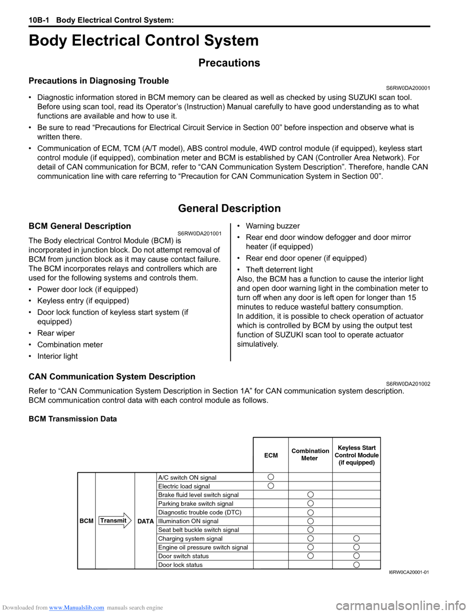
CAN Communication System DescriptionS6RW0DA201002
Refer to “CAN Communication System Description in Section 1A” for CAN communication system description.
BCM communication control data with each control module as follows.
BCM Transmission Data
A/C switch ON signal
Electric load signal
Brake fluid level switch signal
Parking brake switch signal
Diagnostic trouble code (DTC)
Illumination ON signal
Seat belt buckle switch signal
Charging system signal
Engine oil pressure switch signal
Door switch status
Door lock statusECMKeyless Start
Control Module
(if equipped) Combination
Meter
BCMTransmit
DATA
I6RW0CA20001-01