Page 1161 of 1556

Downloaded from www.Manualslib.com manuals search engine Table of Contents 9- i
9
Section 9
CONTENTS
Body, Cab and Accessories
Precautions ................................................. 9-1
Precautions............................................................. 9-1
Precautions on Body, Cab and Accessories ......... 9-1
Precautions for Body Service ................................ 9-1
Fastener Caution for Body Service ....................... 9-1
Wiring Systems........................................ 9A-1
Precautions........................................................... 9A-1
Cautions in Body Electrical System Servicing..... 9A-1
General Description ............................................. 9A-1
Abbreviations ...................................................... 9A-1
Wire / Connector Color Symbols ......................... 9A-1
Symbols and Marks ............................................ 9A-2
How to Read Connector Layout Diagram ........... 9A-4
How to Read Connector Codes and Terminal
Nos.................................................................... 9A-5
How to Read Ground Point ................................. 9A-8
How to Read Power Supply Diagram.................. 9A-9
How to Read System Circuit Diagram................. 9A-9
Connector Layout Diagram ............................... 9A-11
Connector Layout Diagram ............................... 9A-11
Engine Compartment ........................................ 9A-11
Instrument Panel ............................................... 9A-19
Door, Roof......................................................... 9A-25
Floor .................................................................. 9A-28
Rear .................................................................. 9A-32
Ground Point ...................................................... 9A-33
Ground (earth) Point ......................................... 9A-33
Power Supply Diagram ...................................... 9A-34
Power Supply Diagram ..................................... 9A-34
Fuses and the Protected Parts ......................... 9A-36
Fuses in Main Fuse Box ................................... 9A-36
Individual Circuit Fuse Box No. 1 ...................... 9A-37
Individual Circuit Fuse Box No. 2 (In J/B
(Except Taiwan)) ............................................. 9A-38
Individual Circuit Fuse Box No. 2 (In J/B
(Taiwan)) ......................................................... 9A-40
Junction Block (J/B) Connector / Fuse Layout .. 9A-42
Junction Block Inner Circuit (Overview
(Except Taiwan)) ............................................. 9A-43
Junction Block Inner Circuit (Detail (Except
Taiwan)) .......................................................... 9A-45
Junction Block Inner Circuit (Overview
(Taiwan)) ......................................................... 9A-50Junction Block Inner Circuit (Detail (Taiwan)) ... 9A-52
System Circuit Diagram.....................................9A-57
System Circuit Diagram .................................... 9A-57
A-1 Cranking System Circuit Diagram .............. 9A-58
A-2 Charging System Circuit Diagram .............. 9A-59
A-3 Ignition System Circuit Diagram (M15A
engine, M16A engine) ..................................... 9A-60
A-3 Ignition System Circuit Diagram (J20A
engine) ............................................................ 9A-61
A-4 Cooling System Circuit Diagram (M15A
engine, M16A engine) ..................................... 9A-62
A-4 Cooling System Circuit Diagram (J20A
engine) ............................................................ 9A-63
A-5 Engine and A/C Control System Circuit
Diagram (M15A engine) .................................. 9A-64
A-5 Engine and A/C Control System Circuit
Diagram (M16A engine) .................................. 9A-68
A-5 Engine and A/C Control System Circuit
Diagram (J20A engine) ................................... 9A-72
A-6 A/T Control System Circuit Diagram........... 9A-76
A-7 Immobilizer System Circuit Diagram .......... 9A-78
A-8 Body Control System Circuit Diagram
(Except Taiwan) .............................................. 9A-79
A-8 Body Control System Circuit Diagram
(Taiwan) .......................................................... 9A-83
A-10 4WD Control System (Except Taiwan) ..... 9A-87
B-1 Windshield Wiper and Washer Circuit
Diagram........................................................... 9A-88
B-2 Rear Wiper and Washer Circuit Diagram
(Except Taiwan) .............................................. 9A-89
B-2 Rear Wiper and Washer Circuit Diagram
(Taiwan) .......................................................... 9A-90
B-3 Rear Defogger Circuit Diagram (Except
Taiwan) ........................................................... 9A-91
B-3 Rear Defogger Circuit Diagram (Taiwan) ... 9A-92
B-4 Power Window Circuit Diagram .................. 9A-93
B-5 Power Door Lock Circuit Diagram (Except
Taiwan) ........................................................... 9A-95
B-5 Power Door Lock Circuit Diagram
(Taiwan) .......................................................... 9A-97
B-6 Power Mirror Circuit Diagram (Except
Taiwan) ........................................................... 9A-99
B-6 Power Mirror Circuit Diagram (Taiwan) .... 9A-100
B-7 Horn Circuit Diagram ................................ 9A-101
B-8 Seat Heater Circuit Diagram..................... 9A-102
Page 1175 of 1556
Downloaded from www.Manualslib.com manuals search engine Wiring Systems: 9A-8
How to Read Ground PointS6RW0D9101006
Refer to “System Circuit Diagram”.
Refer to “Ground (earth) Point”.
Left side shown
101112
"SYSTEM CIRCUIT DIAGRAM"
"GROUND POINT"
CROSS-REFERENCE
Windoshield
washer
motorIndividual
circuit
fuse box
2015A
Windoshield
wiper
motor E40
E09E20 16
2
1
Off
On
Circuit
breaker
60A-B003-
YEL/BLU
1
205
2
134
67
BLU/BLK
BLK
10
BLK
BLK
9
10
10
BLK
M
BLUBLU/WHTBLU/RED
M
Device body grounding is not given the ground point number.
I5RW0A910992-02
Page 1176 of 1556

Downloaded from www.Manualslib.com manuals search engine 9A-9 Wiring Systems:
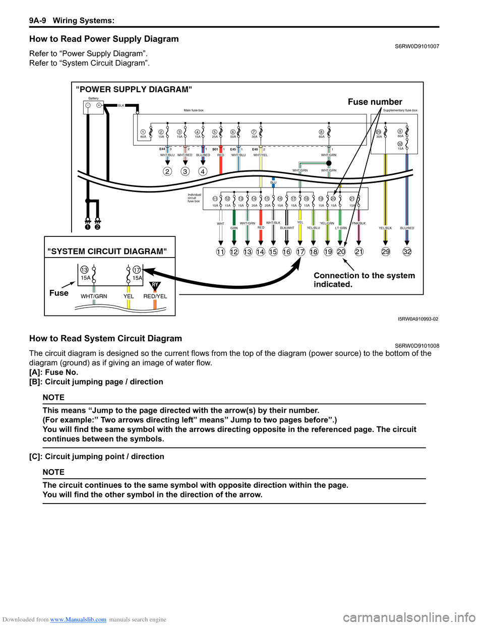
How to Read Power Supply DiagramS6RW0D9101007
Refer to “Power Supply Diagram”.
Refer to “System Circuit Diagram”.
How to Read System Circuit DiagramS6RW0D9101008
The circuit diagram is designed so the current flows from the top of the diagram (power source) to the bottom of the
diagram (ground) as if giving an image of water flow.
[A]: Fuse No.
[B]: Circuit jumping page / direction
NOTE
This means “Jump to the page directed with the arrow(s) by their number.
(For example:” Two arrows directing left” means” Jump to two pages before”.)
You will find the same symbol with the arrows directing opposite in the referenced page. The circuit
continues between the symbols.
[C]: Circuit jumping point / direction
NOTE
The circuit continues to the same symbol with opposite direction within the page.
You will find the other symbol in the direction of the arrow.
Connection to the system
indicated. "POWER SUPPLY DIAGRAM"
-+
1
Battery
80A
215A315A415A525A67850A 30A2930A3215A
960A
60A
BLK
YEL/BLKPNK/BLKLT GRNYEL/GRNYEL/BLUBLK/WHTWHT/BLKWHT/GRNREDGRNWHT
WHT/BLUWHT/REDWHT/BLUWHT/YELWHT/GRN
WHT/GRNWHT/GRN
BLU
BLU/REDRED
YELBLU/RED Individual
circuit
fuse box Main fuse boxSupplementary fuse box
11
11
243
121314151617181920212932
1213141516171819202115A 15A 15A 20A 20A 15A 15A 15A 15A 15A 15A E44321
B011E451E4021
FuseRED/YEL YEL WHT/GRN
15A
15A 1317
"SYSTEM CIRCUIT DIAGRAM"
Fuse number
12
RY
I5RW0A910993-02
Page 1201 of 1556
Downloaded from www.Manualslib.com manuals search engine Wiring Systems: 9A-34
Power Supply Diagram
Power Supply DiagramS6RW0D910D001
G273
J/B
J/B
3
WHT/BLU
GRN/WHT
RED/WHT
4G1473
1
2
8
BLK
21
BLK/GRY
15A
15A15A
2314678
1E3112
WHT
1112141516
BLK/YELGRY
3
YEL/BLU
21
BLU/YEL
4
BLU
RED
WHT
WHT
WHT/RED
11
WHT/GRN
14
WHT/BLU
1516
WHT/RED
GRN
12
30A
9
WHT/BLU
9
30A
20A30A 50A40A
60A
20A15A
15A
BLK
2E3121
WHT/BLU
C282C28311
WHT
BLK
Main fuse box
Starting motor
"A-1"Generator
"A-2"
Battery
80A
50A 50A
4544
43
E3241
E32510
G2734
WHT
YEL
Individual circuit fuse box (No.1)
+B1
LOCK
ACC
ON
STACC IG1 IG2STOUT
IN
+B2
6
GRNBLU
5
Starting motor
relay
10
GRY
10
30A
E382
G33417
1
5
4
3
2
"A-1"
33
10A
I6RW0C910918-03
Page 1225 of 1556
Downloaded from www.Manualslib.com manuals search engine Wiring Systems: 9A-58
A-1 Cranking System Circuit DiagramS6RW0D910E002
Starting motor
relay
W
"A-5"
ECM
E225
C1951C1961
Starting motor
M
BLK
1
BLK/GRY
C2821
Battery
E371
C3433
RED
Individual circuit
fuse box (No.1)
8
30A
33
10A
WHTWHT
J/B
E32510
42
3 1
RED/WHT
ST
ST SIG
YEL/GRNYEL/GRN
YG
"A-5"
ECM
GRN/WHT
G1472
YEL/GRN
YEL/GRN
G2734
+B1
LOCK
ACC
ON
STACC IG1 IG2STOUT
IN
+B2
2P
R
ND2L
Transaxle
range
sensor
C166
E371
C3433
A/T M/T
3
YEL/GRN
YEL
YEL
M15A engine, M16A engine
J20A engine A
9
2AB
6
8AB
B
I6RW0C910933-01
Page 1226 of 1556
Downloaded from www.Manualslib.com manuals search engine 9A-59 Wiring Systems:
A-2 Charging System Circuit DiagramS6RW0D910E003
20E371
C343
20G334
E382
BLK/WHT
BLK/WHT
BLK/WHT
80A Main fuse box
C192
J/B
1C283
IG COIL4315A
20
GeneratorIC
regulator
1
E3255
C19424
WHT/BLU
WB
BCM
"A-8"
1
BLU/YEL
BY
3
BRN/WHT
BW
ECM
"A-5"
9
WHT/BLUBLK
Weld spliceTaiwan
M15A engine,
J20A engine
C312
I6RW0C910934-02
Page 1229 of 1556
Downloaded from www.Manualslib.com manuals search engine Wiring Systems: 9A-62
A-4 Cooling System Circuit Diagram (M15A engine, M16A engine)S6RW0D910E005
E65
4
5
9
"A-5"
Lg
BR
BW
Relay
Motor
E2223
1
2
1
BLU/REDLT GRNBRN/WHT
GRYBLK/RED
BLK/YELBLK/YEL
30ARDTR
10
E2211
2
15AFI
1
3
4
Main relay
BLK
ECM
Individual circuit
fuse box (No.1)
M
I6RW0C910919-01
Page 1230 of 1556
Downloaded from www.Manualslib.com manuals search engine 9A-63 Wiring Systems:
A-4 Cooling System Circuit Diagram (J20A engine)S6RW0D910E040
E65
4
5
9
LT GRN
"A-5"
Lg
BRBBBW
G
BRN/WHT
BW
BLK/YELBLK/YEL
Relay #1
Motor
E2223
1
243
1
BLU/REDBLU/REDBLU/BLKBLKBLU/RED
BLU/RED
GRY
GRYBLU/WHT
GRNGRN
30ARDTR
10
E2211
2
15AFI
1
3
4
Main relay
BLK
BLK
BLK/RED
ECM
"A-5"
ECM
Individual circuit
fuse box (No.1)
4
5
Relay #2
E2231
35
4
Relay #3
E2241
3
M
I7RW01910924-02