2006 SUZUKI SX4 fuse diagram
[x] Cancel search: fuse diagramPage 930 of 1556

Downloaded from www.Manualslib.com manuals search engine 7A-2 Heater and Ventilation:
Schematic and Routing Diagram
Heater and Ventilation Wiring Circuit DiagramS6RW0D7102001
Non–A/C
Manual A/C
Refer to “A/C System Wiring Diagram in Section 7B”.
Auto A/C
Refer to “A/C System Wiring Diagram in Section 7B”.
Component Location
Electronic Control System Components LocationS6RW0D7103001
Refer to “Electronic Control System Components Location in Section 7B” (non-A/C and manual A/C) or “Electronic
Control System Components Location in Section 7B” (auto A/C).
5V
BLK
RED/BLK3
5 72
G154-3
G154-4
G154-7
G154-8
G154-10
G154-13
G155-2
G155-3
G155-7
G155-6
G155-1
G154-9
G154-14
BLK/WHT
YEL
BLU/WHT
RED
RED/BLKRED
GRN
GRN/YEL
RED/YEL
RED/BLU
BLK/ORN
46
8
BLU
YELGRN
WHT
13
1514
[A]21
BLK/RED
12V
BLK/YELBLK/WHTM
BLK
1IG1
IG2
12
BLK/RED
M 10
11
11
BLU/WHT 19
16
17
18 9 20
I6RW0C710003-01
[A]: Illumination control model 6. Blower motor resistor 12. Main fuse box 18. Illumination light
1. Ignition switch 7. Junction block assembly 13. Blower speed selector 19. Rear defogger relay
2. Blower motor 8. BCM 14. Air intake selector 20. Rear defogger
3. HVAC control unit 9. ECM 15. Rear defogger switch 21. Tail light
4. Lighting switch 10. Air intake control actuator 16. “REC” indicator light
5. Blower motor relay 11. To BCM 17. Rear defogger indicator
Page 945 of 1556
![SUZUKI SX4 2006 1.G Service Workshop Manual Downloaded from www.Manualslib.com manuals search engine Air Conditioning System: Manual Type 7B-5
A/C System Wiring DiagramS6RW0D7212002
[A]
7
WHT
GRN5YELBLK
3
G154-3
G154-4
G154-7
G154-8
G154-10
G15 SUZUKI SX4 2006 1.G Service Workshop Manual Downloaded from www.Manualslib.com manuals search engine Air Conditioning System: Manual Type 7B-5
A/C System Wiring DiagramS6RW0D7212002
[A]
7
WHT
GRN5YELBLK
3
G154-3
G154-4
G154-7
G154-8
G154-10
G15](/manual-img/20/7612/w960_7612-944.png)
Downloaded from www.Manualslib.com manuals search engine Air Conditioning System: Manual Type 7B-5
A/C System Wiring DiagramS6RW0D7212002
[A]
7
WHT
GRN5YELBLK
3
G154-3
G154-4
G154-7
G154-8
G154-10
G154-13
G154-5
G154-6
G155-5
G155-2
G155-3
G155-7
G155-6
G155-1
G154-9
G154-14
BLK/WHT
YEL
BLU/WHT
RED
BRN
GRN/WHT
RED/BLK
RED
GRN
GRN/YEL
RED/YEL
RED/BLU
20
21
23 22
BLK/RED
6 2
MBLK/WHTBLK/YEL
M
11
4RED/YEL 1
E01-49
12
E01-16
GRY 13
12V
BLU/WHTE01-3510
E01-48
18
19RED/BLK
BLK/RED
BLK/RED
BRN/WHTE01-60
E01-1
E01-29BLK/WHT
M
BLU/YELBLK/YEL
5V5V 5V
WHT/BLK
9
ORN
14E01-36
C01-12C01-14GRY/REDRED/BLU
E01-41
RED/BLK
RED
WHT
8
BLK
BLK/ORN
BLU IG1
IG2
5V
17
28
29
31
2726 2524
16
16
30
34
33E01-4 E01-19WHTRED
C01-50C01-49WHTRED
32
LT GRN
C01-57
C01-2415
GRY/BLU5V
I6RW0C721002-01
[A]: Illumination control model 9. A/C refrigerant pressure
sensor18. Condenser cooling fan relay 27. Illumination light
1. Ignition switch 10. ECM 19. Condenser cooling fan motor 28. Rear defogger relay
2. Blower motor 11. Air intake control actuator 20. Blower speed selector 29. Rear defogger
3. HVAC control unit 12. Compressor relay 21. A/C switch 30. Main relay
4. Lighting switch 13. Compressor 22. Air intake selector 31. Tail light
5. Blower motor relay 14. Evaporator temperature
sensor23. Rear defogger switch 32. TCM
6. Blower motor resistor 15. ECT sensor 24. “A/C” indicator light 33. To other control module and DLC
7. Junction block assembly 16. To BCM 25. “REC” indicator light 34. ABS control module
8. BCM 17. Main fuse box 26. Rear defogger indicator
Page 997 of 1556

Downloaded from www.Manualslib.com manuals search engine Air Conditioning System: Automatic Type 7B-57
SUN LOAD (W/m2): This parameter indicates the
amount of sunlight detected by sunload sensor.
MODE CONT SWITCH (Air flow selector position,
AUTO, FACE, B/L, FOOT, D/F, DEF): This
parameter indicates the selected position of air flow
selector.
FAN CONT SWITCH (Blower speed selector, AUTO,
OFF, 1st – 8th): This parameter indicates the
selected position of blower speed selector.
FAN DESIRE VOLT (Fan desired voltage, V): This
parameter indicates the consumption voltage of
blower motor.
AIR MIX POS SENSOR (Temperature control
actuator position sensor, V): This parameter
indicates the input signal from position sensor in
temperature control actuator.
MODE POS SENSOR (Air flow control actuator
position sensor, V): This parameter indicates the
input signal from position sensor in air flow control
actuator.
A/C CONT SIG (A/C control signal, ON, OFF): This
parameter indicates the state of A/C switch.BLOWER LOAD SIG (Blower fan load signal, ON,
OFF): ON: Position of blower speed selector is 1st
position or more.
OFF: Position of blower speed selector is OFF
position.
AIR INTAKE MODE (Air intake selector position,
AUTO, FRE, REC): This parameter indicates the
selected position of air intake selector.
REFRIGERANT PRESSURE (A/C refrigerant absolute
pressure, kPa): This parameter indicates the A/C
refrigerant absolute pressure calculated by ECM
A/C COMP CLUCH (A/C compressor magnet clutch,
ON, OFF): This parameter indicates the state of the
A/C compressor magnet clutch.
VEHICLE SPEED (km/h, mph): This parameter
indicates the vehicle speed calculated by ECM.
ENGINE TYPE (Engine type signal, J20, M16 or
M15): This parameter indicates the engine type
signal transmitted by ECM.
METER SPEC (Combination meter spec signal, EU,
UK, US, Canada, DOM): This parameter indicates
the combination meter spec signal transmitted by
combination meter.
Visual InspectionS6RW0D7224009
Check visually the following parts and systems.
DTC B1502: Inside Air Temperature Sensor Circuit MalfunctionS6RW0D7224010
Wiring DiagramInspection item Correction
• Refrigerant leakage and amount
• A/C pipe or hose disconnection,
looseness and
deterioration
• A/C compressor drive belt looseness and damageRefer to “Compressor Drive Belt Inspection
and Adjustment”.
• Battery fluid level and corrosion
of terminal
• Connectors of electric wire harness disconnection and
friction
• Fuses burning
• Parts installation and damage
• Other parts that can be checked visually
5V
G20
1 2 3 4 5 6 7 8 9 10 11 12 13 14
15 16 17 18 19 20 21 24 23 22 25 26 27 28 29 30
ORNORNPNK/BLKG20-10
21
3 [S]
[G]
G20-24
I7RW01722004-01
[S]: Inside air temperature sensor signal circuit 1. HVAC control module 3. To other sensors
[G]: Inside air temperature sensor ground circuit 2. Inside air temperature sensor
Page 1009 of 1556

Downloaded from www.Manualslib.com manuals search engine Air Conditioning System: Automatic Type 7B-69
DTC B1541: Back-Up Power Supply Circuit MalfunctionS6RW0D7224018
Wiring Diagram
DTC Detecting Condition and Trouble Area
NOTE
When checking DTC after connecting battery cable, be sure to turn ignition switch from OFF to ON and
from ON to OFF at least once, or DTC B1541 will be detected.
DTC Troubleshooting
12V5V
WHTG20-7 2
31G201 2 3 4 5 6 7 8 9 10 11 12 13 14
15 16 17 18 19 20 21 24 23 22 25 26 27 28 29 30WHT/RED [B]
I7RW01722011-01
[B]: Back-up power supply circuit 2. Main fuse
1. HVAC control module 3. Circuit fuse
DTC Detecting Condition Trouble Area
• Back-up power supply voltage is lower than specified value continuously.
• When connect battery with vehicle and then, turn ignition switch to ON
position for first time.• Battery voltage supply circuit
• HVAC control module
Step Action Yes No
1Was “Air Conditioning System Check” performed?Go to Step 2. Go to “Air Conditioning
System Check”.
2DTC check
1) Turn ignition switch to ON position for 20 sec. or more.
2) Ignition switch turned OFF and connect scan tool to
DLC.
3) Turn ON ignition switch and check DTC.
Is there DTC B1541?Go to Step 3. Intermittent trouble.
Check for intermittent
referring to “Intermittent
and Poor Connection
Inspection in Section
00”.
3Battery voltage supply circuit check
1) Disconnect connector from HVAC control module with
ignition switch turned OFF.
2) Check for proper connection to back-up power supply
circuit terminal of HVAC control module connector.
3) If OK, measure voltage between back-up power supply
circuit terminal of HVAC control module connector and
vehicle body ground.
Is voltage 10 – 14 V?Substitute a known-
good HVAC control
module and recheck.Back-up power supply
circuit is open or
shorted to ground.
Page 1010 of 1556

Downloaded from www.Manualslib.com manuals search engine 7B-70 Air Conditioning System: Automatic Type
DTC B1546: A/C Refrigerant Pressure MalfunctionS6RW0D7224019
DTC Detecting Condition and Trouble Area
DTC Troubleshooting
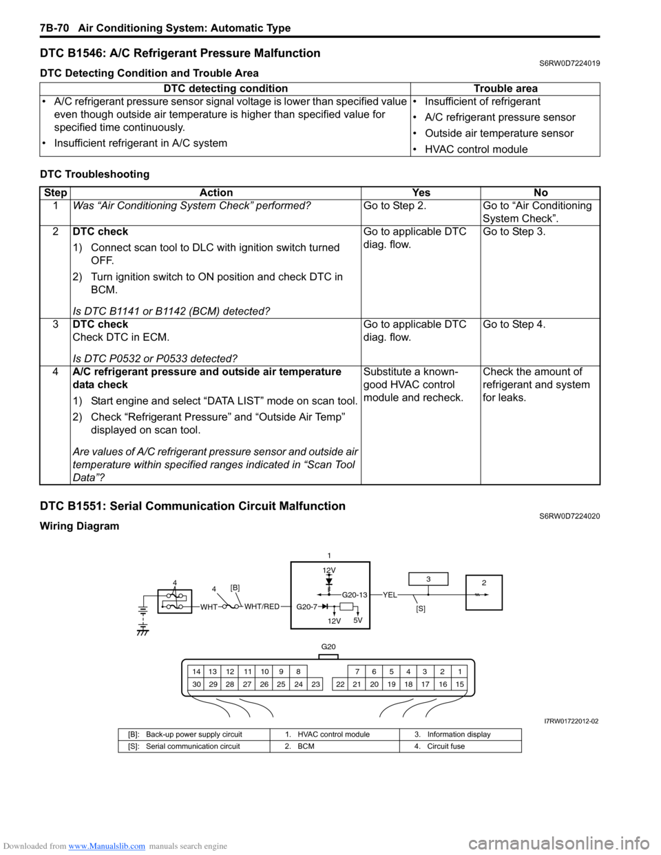
DTC B1551: Serial Communication Circuit MalfunctionS6RW0D7224020
Wiring DiagramDTC detecting condition Trouble area
• A/C refrigerant pressure sensor signal voltage is lower than specified value
even though outside air temperature is higher than specified value for
specified time continuously.
• Insufficient refrigerant in A/C system• Insufficient of refrigerant
• A/C refrigerant pressure sensor
• Outside air temperature sensor
• HVAC control module
Step Action Yes No
1Was “Air Conditioning System Check” performed?Go to Step 2. Go to “Air Conditioning
System Check”.
2DTC check
1) Connect scan tool to DLC with ignition switch turned
OFF.
2) Turn ignition switch to ON position and check DTC in
BCM.
Is DTC B1141 or B1142 (BCM) detected?Go to applicable DTC
diag. flow.Go to Step 3.
3DTC check
Check DTC in ECM.
Is DTC P0532 or P0533 detected?Go to applicable DTC
diag. flow.Go to Step 4.
4A/C refrigerant pressure and outside air temperature
data check
1) Start engine and select “DATA LIST” mode on scan tool.
2) Check “Refrigerant Pressure” and “Outside Air Temp”
displayed on scan tool.
Are values of A/C refrigerant pressure sensor and outside air
temperature within specified ranges indicated in “Scan Tool
Data”?Substitute a known-
good HVAC control
module and recheck.Check the amount of
refrigerant and system
for leaks.
12V
G20
G20-13YEL
1 2 3 4 5 6 7 8 9 10 11 12 13 14
15 16 17 18 19 20 21 24 23 22 25 26 27 28 29 30
1
2 3
[S]WHT/REDWHTG20-7
12V5V
[B]4 4
I7RW01722012-02
[B]: Back-up power supply circuit 1. HVAC control module 3. Information display
[S]: Serial communication circuit 2. BCM 4. Circuit fuse
Page 1058 of 1556

Downloaded from www.Manualslib.com manuals search engine 8B-19 Air Bag System:
Scan Tool Data Definition
Buck Up Volt (V)
This parameter indicates the capacity of the backup
capacitor installed to maintain the ignition current (as
much as possible) even when the power supply to SDM
that ignites the inflator is shut off.
Battery Voltage (V)
Battery voltage is an analog input signal read by SDM.
Dirv Air Bag Ini Res (Driver air bag initiator
resistance) (ohm)
This parameter indicates the resistance of the driver air
bag initiator circuit.
Pass Air Bag Ini Res (Passenger air bag initiator
resistance) (ohm)
This parameter indicates the resistance of the passenger
air bag initiator circuit.
Driv Preten Ini Res (Driver pretensioner initiator
resistance) (ohm)
This parameter indicates the resistance of the driver seat
belt pretensioner initiator circuit.Pass Preten Ini Res (Passenger pretensioner
initiator resistance) (ohm)
This parameter indicates the resistance of the passenger
seat belt pretensioner initiator circuit.
Driv Sidebag Ini Res (Driver side-air bag initiator
resistance) (ohm)
This parameter indicates the resistance of the driver
side-air bag initiator circuit.
Pass Sidebag Ini Res (Passenger side-air bag
initiator resistance) (ohm)
This parameter indicates the resistance of the passenger
side-air bag initiator circuit.
Driv curtain Ini RES (Driver side curtain-air bag
initiator resistance) (ohm)
This parameter indicates the resistance of the driver side
curtain-air bag initiator circuit.
Pass curtain Ini RES (Passenger side curtain-air bag
initiator resistance) (ohm)
This parameter indicates the resistance of the passenger
side curtain-air bag initiator circuit.
System ID (4ch/8ch)
This parameter indicates the number of initiator circuits.
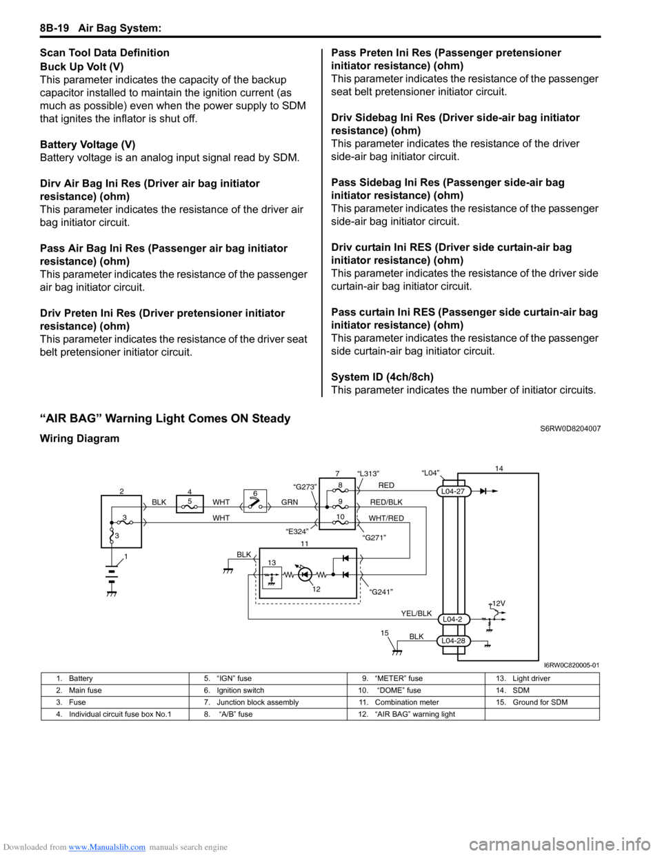
“AIR BAG” Warning Light Comes ON SteadyS6RW0D8204007
Wiring Diagram
“L04”14
5
9RED
RED/BLK GRN
YEL/BLK
BLK
8 7
11
12
15
L04-2
L04-28
L04-27
“G241” “G271” “L313”
13
12V
6
1BLK
WHT WHT
WHT/RED 2
34
310 BLK
“G273”
“E324”
I6RW0C820005-01
1. Battery 5. “IGN” fuse 9. “METER” fuse 13. Light driver
2. Main fuse 6. Ignition switch 10. “DOME” fuse 14. SDM
3. Fuse 7. Junction block assembly 11. Combination meter 15. Ground for SDM
4. Individual circuit fuse box No.1 8. “A/B” fuse 12. “AIR BAG” warning light
Page 1062 of 1556

Downloaded from www.Manualslib.com manuals search engine 8B-23 Air Bag System:
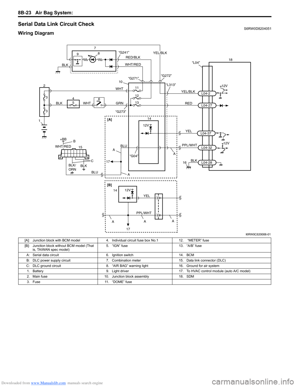
Serial Data Link Circuit CheckS6RW0D8204051
Wiring Diagram
1
2
3
3
18
12V
RED 7
14 9
10
“L313”
“G273”
YEL/BLKL04-2
L04-27 “L04”
PPL/WHT
“G04”L04-3212V
8
GRN
15
+BB
56WHTWHT
4
BLUBLU
BLK
16
11
12
“G241”
13
BLK
L04-28
RED/BLK
WHT/REDYEL/BLK
BLK“G271”
“G272”
WHT/RED
BLK/
ORNBLK
B
C
A A
A
17
[A]
A
[B]
12V
PPL/WHTYEL14
17A
A
YELL04-37
12V
I6RW0C820006-01
[A]: Junction block with BCM model 4. Individual circuit fuse box No.1 12. “METER” fuse
[B]: Junction block without BCM model (That
is, TAIWAN spec model)5. “IGN” fuse 13. “A/B” fuse
A: Serial data circuit 6. Ignition switch 14. BCM
B: DLC power supply circuit 7. Combination meter 15. Data link connector (DLC)
C: DLC ground circuit 8. “AIR BAG” warning light 16. Ground for air system
1. Battery 9. Light driver 17. To HVAC control module (auto A/C model)
2. Main fuse 10. Junction block assembly 18. SDM
3. Fuse 11. “DOME” fuse
Page 1065 of 1556

Downloaded from www.Manualslib.com manuals search engine Air Bag System: 8B-26
DTC B1014: “AIR BAG” Warning Light CircuitS6RW0D8204011
Wiring Diagram
Refer to““AIR BAG” Warning Light Comes ON Steady”.
DTC Detecting Condition and Trouble Area
DTC Troubleshooting
NOTE
Upon completion of inspection and repair work, perform the following items.
• Reconnect all air bag system components and ensure all components are properly mounted.
• Clear DTCs referring to “DTC Clearance”, if any.
• Repeat “Air Bag Diagnostic System Check” to confirm that the trouble has been corrected.
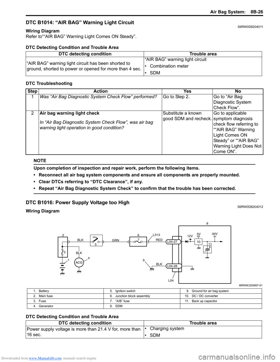
DTC B1016: Power Supply Voltage too HighS6RW0D8204012
Wiring Diagram
DTC Detecting Condition and Trouble AreaDTC detecting condition Trouble area
“AIR BAG” warning light circuit has been shorted to
ground, shorted to power or opened for more than 4 sec.“AIR BAG” warning light circuit
• Combination meter
•SDM
Step Action Yes No
1Was “Air Bag Diagnostic System Check Flow” performed?Go to Step 2. Go to “Air Bag
Diagnostic System
Check Flow”.
2Air bag warning light check
In “Air Bag Diagnostic System Check Flow”, was air bag
warning light operation in good condition?Substitute a known
good SDM and recheck.Go to applicable
symptom diagnosis
check flow referring to
““AIR BAG” Warning
Light Comes ON
Steady” or ““AIR BAG”
Warning Light Does Not
Come ON”.
BLK
L04
7
RED
GRN L313
98
L04-28
L04-27
1
2
3
BLK
45 BLK6
ACG
10
12V5V30V
11
I6RW0C820007-01
1. Battery 5. Ignition switch 9. Ground for air bag system
2. Main fuse 6. Junction block assembly 10. DC / DC converter
3. Fuse 7. “A/B” fuse 11. Back up capacitor
4. Generator 8. SDM
DTC detecting condition Trouble area
Power supply voltage is more than 21.4 V for, more than
16 sec.• Charging system
•SDM