2006 SUZUKI SWIFT tel
[x] Cancel search: telPage 990 of 1496
Downloaded from www.Manualslib.com manuals search engine 7B-42 Air Conditioning System: Automatic Type
Abnormal Noise Symptom Diagnosis of A/C
System
S7RS0B7224002
Refer to “Abnormal Noise Symptom Diagnosis of A/C
System”.
DTC CheckS7RS0B7224003
Using SUZUKI Scan Tool1) Turn ignition switch to OFF position.
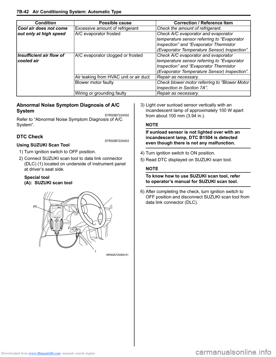
2) Connect SUZUKI scan tool to data link connector (DLC) (1) located on underside of instrument panel
at driver’s seat side.
Special tool
(A): SUZUKI scan tool 3) Light over sunload sensor vertically with an
incandescent lamp of approximately 100 W apart
from about 100 mm (3.94 in.).
NOTE
If sunload sensor is not lighted over with an
incandescent lamp, DTC B1504 is detected
even though there is not any malfunction.
4) Turn ignition switch to ON position.
5) Read DTC displayed on SUZUKI scan tool.
NOTE
To know how to use SUZUKI scan tool, refer
to operator’s manual for SUZUKI scan tool.
6) After completing the check, turn ignition switch to
OFF position and disconnect SUZUKI scan tool from
data link connector (DLC).
Cool air does not come
out only at high speed
Excessive amount of refrigerant
Check the amount of refrigerant.
A/C evaporator frosted Check A/C evaporator and evaporator
temperature sensor referring to “Evaporator
Inspection” and “Evaporator Thermistor
(Evaporator Temperature Sensor) Inspection”.
Insufficient air flow of
cooled air A/C evaporator clogged or frosted
Check A/C evaporator and evaporator
temperature sensor referring to “Evaporator
Inspection” and “Evaporator Thermistor
(Evaporator Temperature Sensor) Inspection”.
Air leaking from HVAC unit or air duct Repair as necessary.
Blower motor faulty Check blower motor referring to “Blower Motor
Inspection in Section 7A”.
Wiring or grounding faulty Repair as necessary.
Condition Possible cause Correction / Reference Item
(A)
1
I5RS0A722005-01
Page 991 of 1496
Downloaded from www.Manualslib.com manuals search engine Air Conditioning System: Automatic Type 7B-43
Not Using SUZUKI Scan Tool
Current DTC mode1) Light over sunload sensor vertically with an incandescent lamp of approximately 100 W apart
from about 100 mm (3.94 in.).
NOTE
If sunload sensor is not lighted over with an
incandescent lamp, DTC B1504 is detected
as current DTC even though there is not any
malfunction.
2) Start engine.
3) Wait for 20 seconds or more after engine started and set temperature selector to 25 °C (77 °F).
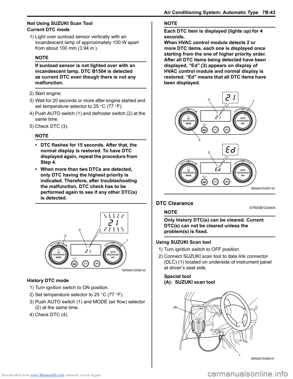
4) Push AUTO switch (1) and defroster switch (2) at the same time.
5) Check DTC (3).
NOTE
• DTC flashes for 15 seconds. After that, the normal display is rest ored. To have DTC
displayed again, repeat the procedure from
Step 4.
• When more than two DTCs are detected, only DTC having the highest priority is
indicated. Therefore, after troubleshooting
the malfunction, DTC check has to be
performed again to see if any other DTC(s)
is detected.
History DTC mode
1) Turn ignition switch to ON position.
2) Set temperature selector to 25 °C (77 °F).
3) Push AUTO switch (1) and MODE (air flow) selector
(2) at the same time.
4) Check DTC (4).
NOTE
Each DTC item is displayed (lights up) for 4
seconds.
When HVAC control module detects 2 or
more DTC items, each one is displayed once
starting from the one of higher priority order.
After all DTC items being detected have been
displayed, “Ed” (3) appears on display of
HVAC control module and normal display is
restored. “Ed” means that all DTC items have
been displayed.
DTC ClearanceS7RS0B7224004
NOTE
Only history DTC(s) can be cleared. Current
DTC(s) can not be cleared unless the
problem(s) is fixed.
Using SUZUKI Scan tool
1) Turn ignition switch to OFF position.
2) Connect SUZUKI scan tool to data link connector (DLC) (1) located on underside of instrument panel
at driver’s seat side.
Special tool
(A): SUZUKI scan tool1
2
3
I5RS0A722006-02
1
2 34
I5RS0A722007-02
(A)
1
I5RS0A722005-01
Page 992 of 1496
Downloaded from www.Manualslib.com manuals search engine 7B-44 Air Conditioning System: Automatic Type
3) Light over sunload sensor vertically with an incandescent lamp approximately 100 W apart from
about 100 mm (3.94 in.).
NOTE
If sunload sensor is not lighted over with an
incandescent lamp, DTC B1504 is detected
as current DTC even though there is not any
malfunction.
4) Turn ignition switch to ON position.
5) Erase DTC according to instructions displayed on SUZUKI scan tool.
NOTE
To know how to use SUZUKI scan tool, refer
to operator’s manual for SUZUKI scan tool.
6) After completing the clearance, turn ignition switch to OFF position, and then di sconnect SUZUKI scan
tool from DLC.
Not Using SUZUKI Scan Tool 1) Turn ignition switch to ON position.
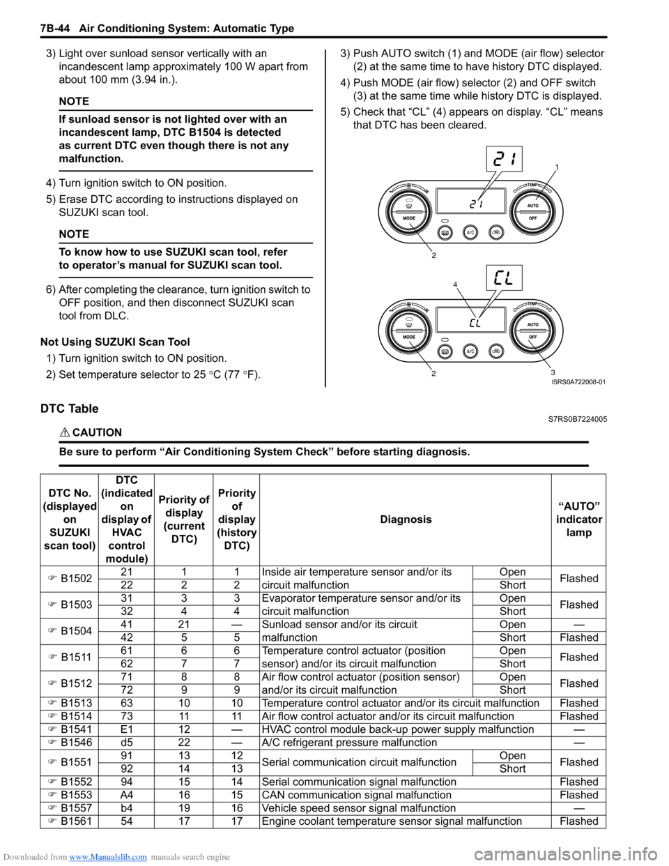
2) Set temperature selector to 25 °C (77 °F). 3) Push AUTO switch (1) and
MODE (air flow) selector
(2) at the same time to have history DTC displayed.
4) Push MODE (air flow) selector (2) and OFF switch (3) at the same time while history DTC is displayed.
5) Check that “CL” (4) appears on display. “CL” means that DTC has been cleared.
DTC TableS7RS0B7224005
CAUTION!
Be sure to perform “Air Conditioning Sy stem Check” before starting diagnosis.
1
2
3
2
4
I5RS0A722008-01
DTC No.
(displayed on
SUZUKI
scan tool) DTC
(indicated on
display of HVAC
control
module) Priority of
display
(current DTC) Priority
of
display
(history DTC) Diagnosis
“AUTO”
indicator lamp
�) B1502 21 1 1 Inside air temperature sensor and/or its
circuit malfunction Open
Flashed
22 2 2 Short
�) B1503 31 3 3 Evaporator temperature sensor and/or its
circuit malfunction Open
Flashed
32 4 4 Short
�) B1504 41 21 — Sunload sensor and/or its circuit
malfunction Open —
42 5 5 Short Flashed
�) B1511 61 6 6 Temperature control actuator (position
sensor) and/or its circuit malfunction Open
Flashed
62 7 7 Short
�) B1512 71 8 8 Air flow control actuator (position sensor)
and/or its circuit malfunction Open
Flashed
72 9 9 Short
�) B1513 63 10 10 Temperature control actuator and/or its circuit malfunction Flashed
�) B1514 73 11 11 Air flow control actuator and/or its circuit malfunction Flashed
�) B1541 E1 12 — HVAC control module back-up power supply malfunction —
�) B1546 d5 22 — A/C refrigerant pressure malfunction —
�) B1551 91 13 12
Serial communication circuit malfunction Open
Flashed
92 14 13 Short
�) B1552 94 15 14 Serial communication signal malfunction Flashed
�) B1553 A4 16 15 CAN communication signal malfunction Flashed
�) B1557 b4 19 16 Vehicle speed sensor signal malfunction —
�) B1561 54 17 17 Engine coolant temperature sensor signal malfunction Flashed
Page 1021 of 1496
Downloaded from www.Manualslib.com manuals search engine Air Conditioning System: Automatic Type 7B-73
HVAC Unit Removal and InstallationS7RS0B7226003
Refer to “HVAC Unit Removal and Installation”.
Temperature Control Actuator Removal and
Installation
S7RS0B7226004
Removal1) Disconnect negative (–) cable at battery.
2) Remove steering column hol e cover from instrument
panel.
3) Remove foot duct from HVAC unit.
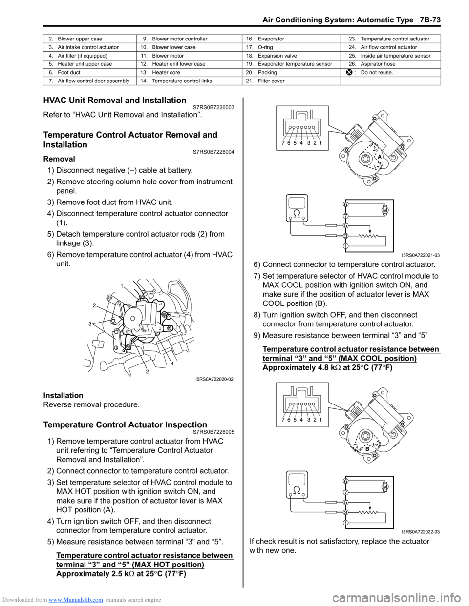
4) Disconnect temperature control actuator connector (1).
5) Detach temperature control actuator rods (2) from linkage (3).
6) Remove temperature control actuator (4) from HVAC unit.
Installation
Reverse removal procedure.
Temperature Control Actuator InspectionS7RS0B7226005
1) Remove temperature control actuator from HVAC unit referring to “Temperature Control Actuator
Removal and Installation”.
2) Connect connector to temperature control actuator.
3) Set temperature selector of HVAC control module to MAX HOT position with ignition switch ON, and
make sure if the position of actuator lever is MAX
HOT position (A).
4) Turn ignition switch OFF, and then disconnect connector from temperature control actuator.
5) Measure resistance between terminal “3” and “5”.
Temperature control actuator resistance between
terminal “3” and “5” (MAX HOT position)
Approximately 2.5 k Ω at 25 °C (77 °F) 6) Connect connector to tem
perature control actuator.
7) Set temperature selector of HVAC control module to MAX COOL position with ignition switch ON, and
make sure if the position of actuator lever is MAX
COOL position (B).
8) Turn ignition switch OFF, and then disconnect connector from temperature control actuator.
9) Measure resistance between terminal “3” and “5”
Temperature control actuator resistance between
terminal “3” and “5” (MAX COOL position)
Approximately 4.8 k Ω at 25 °C (77 °F)
If check result is not satisfactory, replace the actuator
with new one.
2. Blower upper case 9. Blower motor controller 16. Evaporator 23. Temperature control actuator
3. Air intake control actuator 10. Blower lower case 17. O-ring24. Air flow control actuator
4. Air filter (if equipped) 11. Blower motor 18. Expansion valve25. Inside air temperature sensor
5. Heater unit upper case 12. Heater unit lower case 19. Evaporator temperature sensor 26. Aspirator hose
6. Foot duct 13. Heater core 20. Packing : Do not reuse.
7. Air flow control door assembly 14. Temperature control links 21. Filter cover
1
2
2
3
4
I5RS0A722020-02
I5RS0A722021-03
I5RS0A722022-03
Page 1022 of 1496
Downloaded from www.Manualslib.com manuals search engine 7B-74 Air Conditioning System: Automatic Type
Air Flow Control Actuator Removal and
Installation
S7RS0B7226006
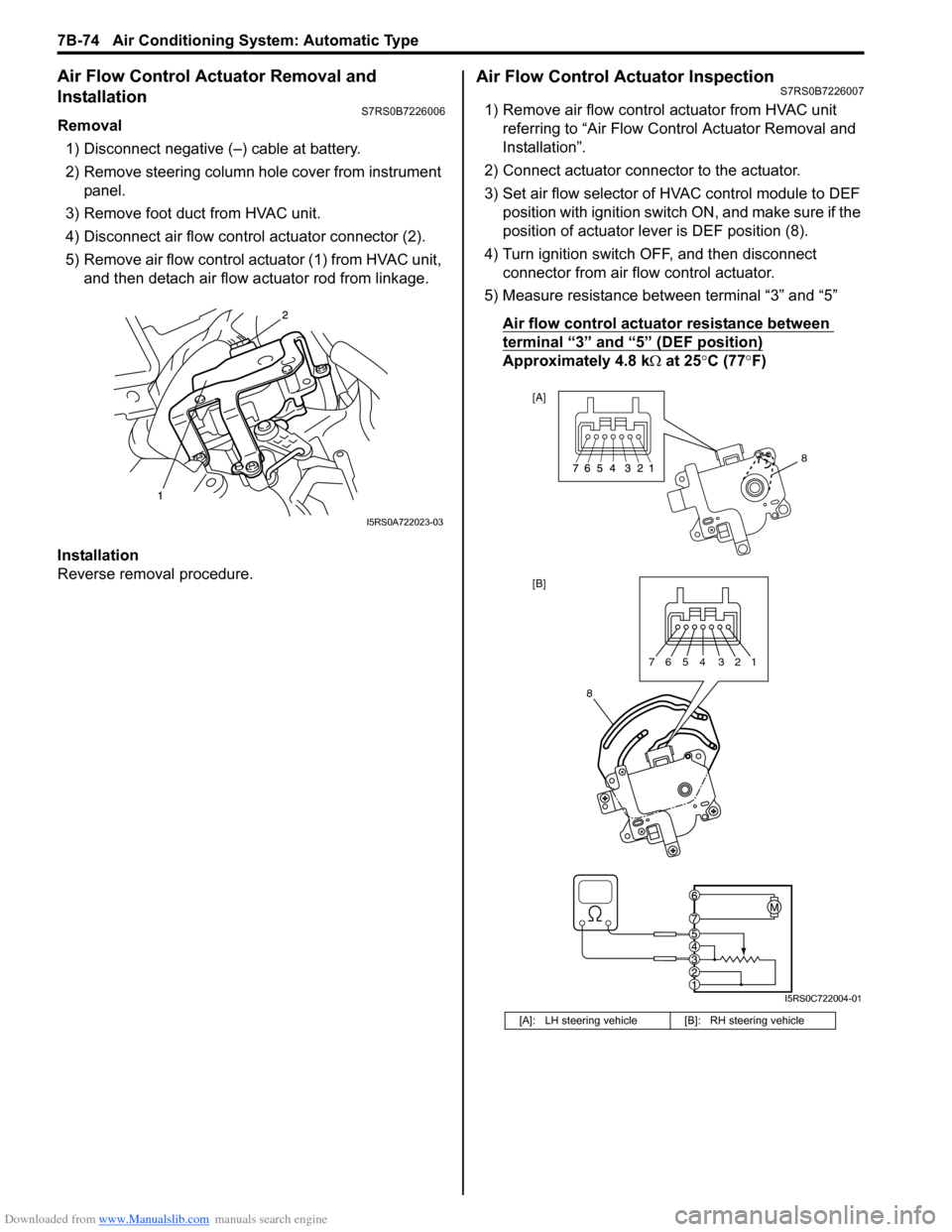
Removal1) Disconnect negative (–) cable at battery.
2) Remove steering column hol e cover from instrument
panel.
3) Remove foot duct from HVAC unit.
4) Disconnect air flow contro l actuator connector (2).
5) Remove air flow control actuator (1) from HVAC unit, and then detach air flow actuator rod from linkage.
Installation
Reverse removal procedure.
Air Flow Control Actuator InspectionS7RS0B7226007
1) Remove air flow control actuator from HVAC unit referring to “Air Flow C ontrol Actuator Removal and
Installation”.
2) Connect actuator connector to the actuator.
3) Set air flow selector of HVAC control module to DEF position with ignition switch ON, and make sure if the
position of actuator lever is DEF position (8).
4) Turn ignition switch OFF, and then disconnect connector from air flow control actuator.
5) Measure resistance between terminal “3” and “5”
Air flow control actuator resistance between
terminal “3” and “5” (DEF position)
Approximately 4.8 k Ω at 25 °C (77 °F)
I5RS0A722023-03
[A]: LH steering vehicle [B]: RH steering vehicle
8
[A]
[B]
8
7654 321
I5RS0C722004-01
Page 1023 of 1496
Downloaded from www.Manualslib.com manuals search engine Air Conditioning System: Automatic Type 7B-75
6) Connect connector to air flow control actuator.
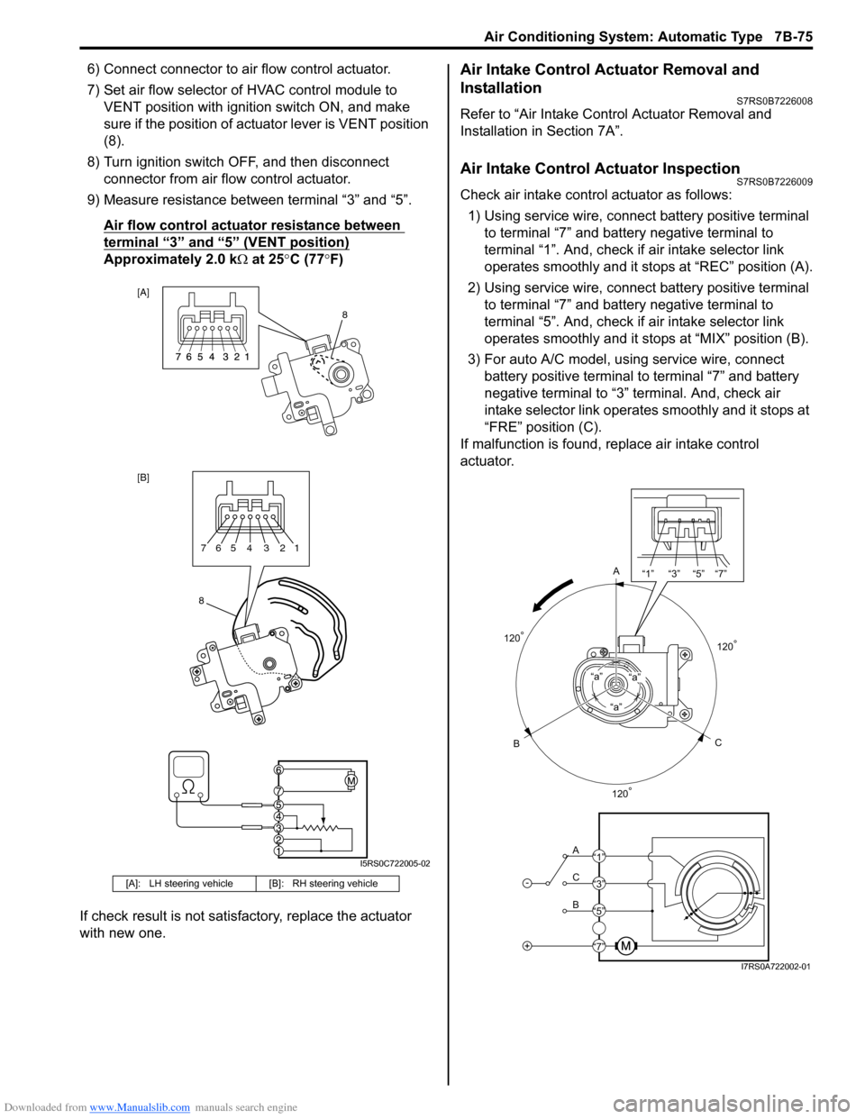
7) Set air flow selector of HVAC control module to VENT position with ignition switch ON, and make
sure if the position of act uator lever is VENT position
(8).
8) Turn ignition switch OFF, and then disconnect connector from air flow control actuator.
9) Measure resistance between terminal “3” and “5”.
Air flow control actuator resistance between
terminal “3” and “5” (VENT position)
Approximately 2.0 k Ω at 25 °C (77 °F)
If check result is not satisfactory, replace the actuator
with new one.
Air Intake Control Actuator Removal and
Installation
S7RS0B7226008
Refer to “Air Intake Control Actuator Removal and
Installation in Section 7A”.
Air Intake Control Actuator InspectionS7RS0B7226009
Check air intake contro l actuator as follows:
1) Using service wire, connect battery positive terminal
to terminal “7” and battery negative terminal to
terminal “1”. And, check if air intake selector link
operates smoothly and it stops at “REC” position (A).
2) Using service wire, connect battery positive terminal
to terminal “7” and battery negative terminal to
terminal “5”. And, check if air intake selector link
operates smoothly and it stops at “MIX” position (B).
3) For auto A/C model, using service wire, connect battery positive terminal to terminal “7” and battery
negative terminal to “3” terminal. And, check air
intake selector link operates smoothly and it stops at
“FRE” position (C).
If malfunction is found, replace air intake control
actuator.
[A]: LH steering vehicl e [B]: RH steering vehicle
[A]
[B]
8
8765 4 3 21
I5RS0C722005-02
A
C
B“a”
“a”“a”
-
+
A
C
B “1” “3” “5” “7”
“1”
“3”
“5”
“7”
120
°
120° 120
°
I7RS0A722002-01
Page 1024 of 1496
Downloaded from www.Manualslib.com manuals search engine 7B-76 Air Conditioning System: Automatic Type
Actuator Linkage InspectionS7RS0B7226010
• Check if each actuator linkage operates smoothly.
• Check actuator rod for bend.
• Check each actuator linkage for breakage.
• Make sure if there is not any obstruction in operating range of actuator linkage.
If any malfunction is found, repair or replace faulty
part(s).
Blower Motor Controller Removal and
Installation
S7RS0B7226011
Refer to “Blower Motor Resistor Removal and
Installation in Section 7A”.
Blower Motor Controller InspectionS7RS0B7226012
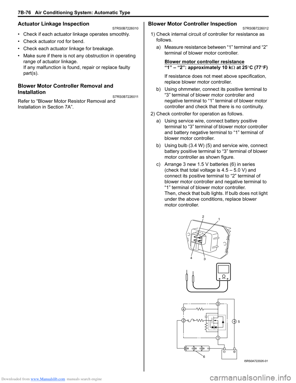
1) Check internal circuit of controller for resistance as follows.
a) Measure resistance between “1” terminal and “2” terminal of blower motor controller.
Blower motor cont roller resistance
“1” – “2”: approximately 10 k Ω at 25 °C (77 °F)
If resistance does not meet above specification,
replace blower motor controller.
b) Using ohmmeter, connect its positive terminal to “3” terminal of blower motor controller and
negative terminal to “1” terminal of blower motor
controller and check that there is no continuity.
2) Check controller for operation as follows. a) Using service wire, connect battery positive terminal to “3” terminal of blower motor controller
and battery negative terminal to “1” terminal of
blower motor controller.
b) Using bulb (3.4 W) (5) and service wire, connect battery positive terminal to “3” terminal of blower
motor controller as shown figure.
c) Arrange 3 new 1.5 V batteries (6) in series (check that total voltage is 4.5 – 5.0 V) and
connect its positive term inal to “2” terminal of
blower motor controller and negative terminal to
“1” terminal of blower motor controller.
Then, check that bulb lights. If bulb does not light
under the above conditions, replace blower
motor controller.
3
1
2
4
2
1
3
4
5
6I5RS0A722026-01
Page 1025 of 1496
Downloaded from www.Manualslib.com manuals search engine Air Conditioning System: Automatic Type 7B-77
HVAC Control Module Removal and InstallationS7RS0B7226013
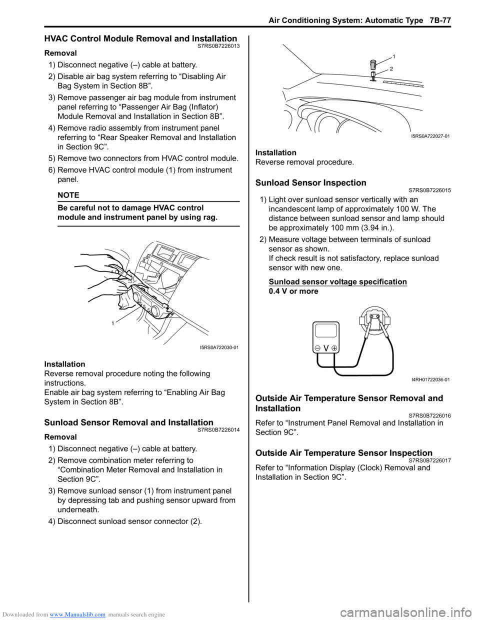
Removal1) Disconnect negative (–) cable at battery.
2) Disable air bag system referring to “Disabling Air Bag System in Section 8B”.
3) Remove passenger air bag module from instrument panel referring to “Passenger Air Bag (Inflator)
Module Removal and Installation in Section 8B”.
4) Remove radio assembly from instrument panel referring to “Rear Speaker Removal and Installation
in Section 9C”.
5) Remove two connectors fr om HVAC control module.
6) Remove HVAC control modu le (1) from instrument
panel.
NOTE
Be careful not to damage HVAC control
module and instrument panel by using rag.
Installation
Reverse removal procedure noting the following
instructions.
Enable air bag system referring to “Enabling Air Bag
System in Section 8B”.
Sunload Sensor Removal and InstallationS7RS0B7226014
Removal
1) Disconnect negative (–) cable at battery.
2) Remove combination meter referring to “Combination Meter Removal and Installation in
Section 9C”.
3) Remove sunload sensor (1) from instrument panel by depressing tab and pushing sensor upward from
underneath.
4) Disconnect sunload sensor connector (2). Installation
Reverse removal procedure.
Sunload Sensor InspectionS7RS0B7226015
1) Light over sunload sensor vertically with an
incandescent lamp of approximately 100 W. The
distance between sunload sensor and lamp should
be approximately 100 mm (3.94 in.).
2) Measure voltage between terminals of sunload sensor as shown.
If check result is not satisfactory, replace sunload
sensor with new one.
Sunload sensor voltage specification
0.4 V or more
Outside Air Temperature Sensor Removal and
Installation
S7RS0B7226016
Refer to “Instrument Panel Re moval and Installation in
Section 9C”.
Outside Air Temperature Sensor InspectionS7RS0B7226017
Refer to “Information Display (Clock) Removal and
Installation in Section 9C”.
1
I5RS0A722030-01
1
2
I5RS0A722027-01
I4RH01722036-01