2006 SUZUKI SWIFT tel
[x] Cancel search: telPage 1162 of 1496
Downloaded from www.Manualslib.com manuals search engine 8B-124 Air Bag System:
21) Disconnect adapter cable (special tool) from air bag (inflator) module or seat belt pretensioner as soon as
possible. This will preven t adapter cable (special
tool) from damage due to possible contact with hot
air bag (inflator) module or hot seat belt
pretensioner.
22) Check adapter cable connector as follows. Adapter cable connector (special tool) is designed to
be reused. However it should be inspected for
damage after deployment and replaced if necessary.
23) With air bag (inflator) modules deployed and seat belt pretensioners acti vated, vehicle may be
scrapped in the same manner as non-air bag system
/ seat belt pretensioner equipped vehicle.
NOTE
Remaining steps are to be followed in the
unlikely event that air bag (inflator) module
did not deploy or seat belt pretensioner did
not activate.
24) Remove undeployed air bag (inflator) module(s) and/ or inactivated seat belt pretensioner(s) from vehicle.
For driver air bag (inflator) module, refer to “Driver
Air Bag (Inflator) Module Removal and Installation”.
For passenger air bag (inflator) module, refer to
“Passenger Air Bag (Inflator) Module Removal and
Installation”. For seat belt pretensioner, refer to
“Front Seat Belt Removal an d Installation in Section
8A”.
25) Temporarily store undeployed air bag (inflator) module referring to “Precautions on Service and
Diagnosis of Air Bag System” for details.
26) Contact your local distribu tor for further assistance.
Deployed Air Bag (Inflator) Module and
Activated Seat Belt Pretensioner Disposal
S7RS0B8206019
WARNING!
Failure to follow proper air bag (inflator)
module and seat belt pretensioner disposal
procedures can result in air bag deployment
and pretensioner activation which may cause
personal injury. The undeployed air bag
(inflator) module and the inactivated seat belt
pretensioner must not be disposed of
through normal refuse channels.
The undeployed air bag (inflator) module and
the inactivated seat belt pretensioner
contains substances that can cause severe
illness or personal injury if the sealed
container is damaged during disposal.
Deployed air bag (inflator) module and the activated seat
belt pretensioner can be disposed of through normal
refuse channels just like any other parts. For their
disposal, however, the following points should be noted.
• The air bag (inflator) module and the seat belt
pretensioner immediately after deployment / activation
is very hot. Wait for 30 minu tes to cool it off before
handling it.
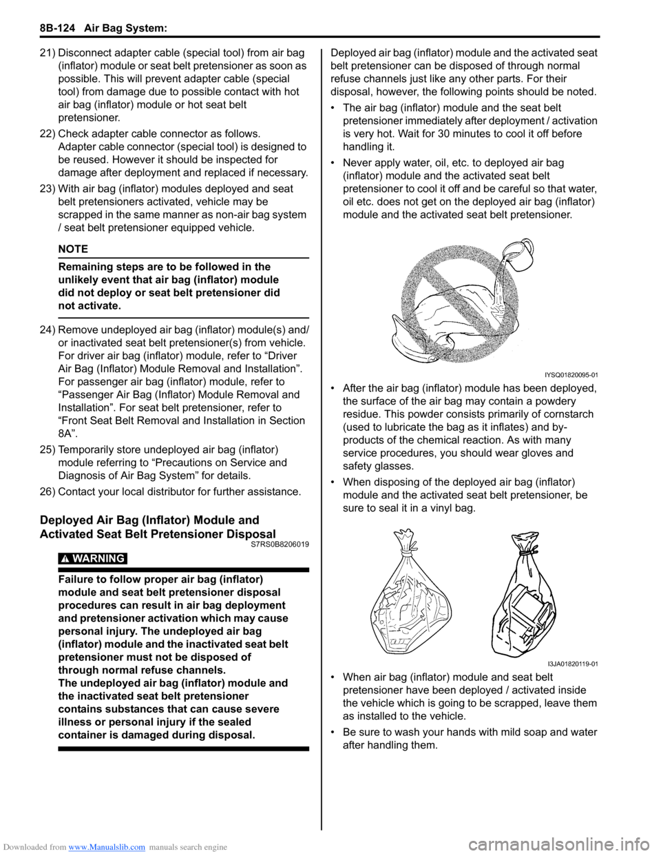
• Never apply water, oil, etc. to deployed air bag (inflator) module and the activated seat belt
pretensioner to cool it off and be careful so that water,
oil etc. does not get on the deployed air bag (inflator)
module and the activated seat belt pretensioner.
• After the air bag (inflator) module has been deployed, the surface of the air bag may contain a powdery
residue. This powder consists primarily of cornstarch
(used to lubricate the bag as it inflates) and by-
products of the chemical reaction. As with many
service procedures, you should wear gloves and
safety glasses.
• When disposing of the deployed air bag (inflator) module and the activated seat belt pretensioner, be
sure to seal it in a vinyl bag.
• When air bag (inflator) module and seat belt pretensioner have been deployed / activated inside
the vehicle which is going to be scrapped, leave them
as installed to the vehicle.
• Be sure to wash your hand s with mild soap and water
after handling them.
IYSQ01820095-01
I3JA01820119-01
Page 1332 of 1496
Downloaded from www.Manualslib.com manuals search engine 9E-5 Glass / Windows / Mirrors:
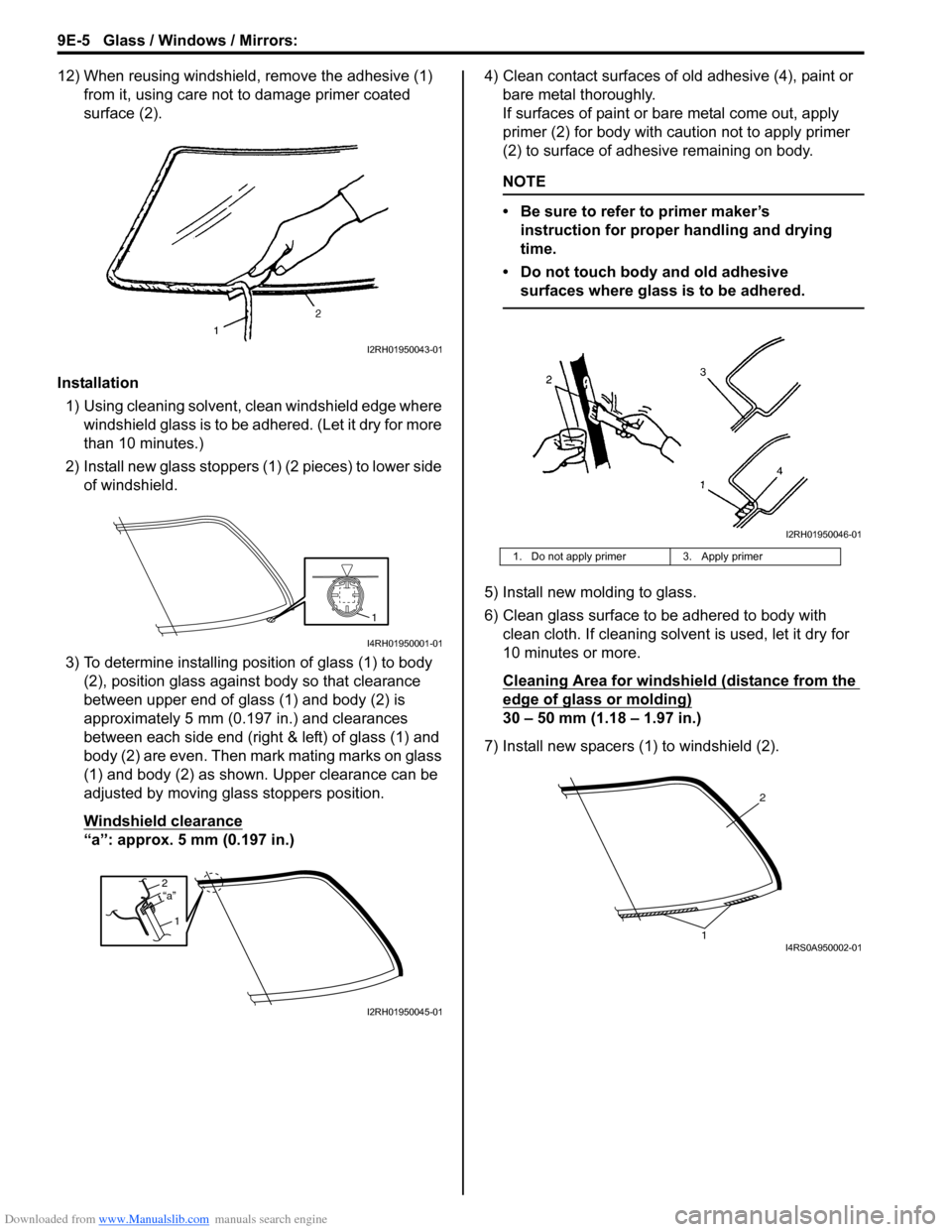
12) When reusing windshield, remove the adhesive (1) from it, using care not to damage primer coated
surface (2).
Installation 1) Using cleaning solvent, clean windshield edge where windshield glass is to be adhered. (Let it dry for more
than 10 minutes.)
2) Install new glass stoppers (1) (2 pieces) to lower side of windshield.
3) To determine installing position of glass (1) to body (2), position glass against body so that clearance
between upper end of glass (1) and body (2) is
approximately 5 mm (0.197 in.) and clearances
between each side end (right & left) of glass (1) and
body (2) are even. Then mark mating marks on glass
(1) and body (2) as shown. Upper clearance can be
adjusted by moving glass stoppers position.
Windshield clearance
“a”: approx. 5 mm (0.197 in.) 4) Clean contact surfaces of old adhesive (4), paint or
bare metal thoroughly.
If surfaces of paint or ba re metal come out, apply
primer (2) for body with caution not to apply primer
(2) to surface of adhesive remaining on body.
NOTE
• Be sure to refer to primer maker’s instruction for proper handling and drying
time.
• Do not touch body and old adhesive surfaces where glass is to be adhered.
5) Install new molding to glass.
6) Clean glass surface to be adhered to body with clean cloth. If cleaning solvent is used, let it dry for
10 minutes or more.
Cleaning Area for windshie ld (distance from the
edge of glass or molding)
30 – 50 mm (1.18 – 1.97 in.)
7) Install new spacers (1) to windshield (2).
I2RH01950043-01
1
I4RH01950001-01
2
1“a”
I2RH01950045-01
1. Do not apply primer 3. Apply primer
I2RH01950046-01
2
1I4RS0A950002-01
Page 1334 of 1496
Downloaded from www.Manualslib.com manuals search engine 9E-7 Glass / Windows / Mirrors:
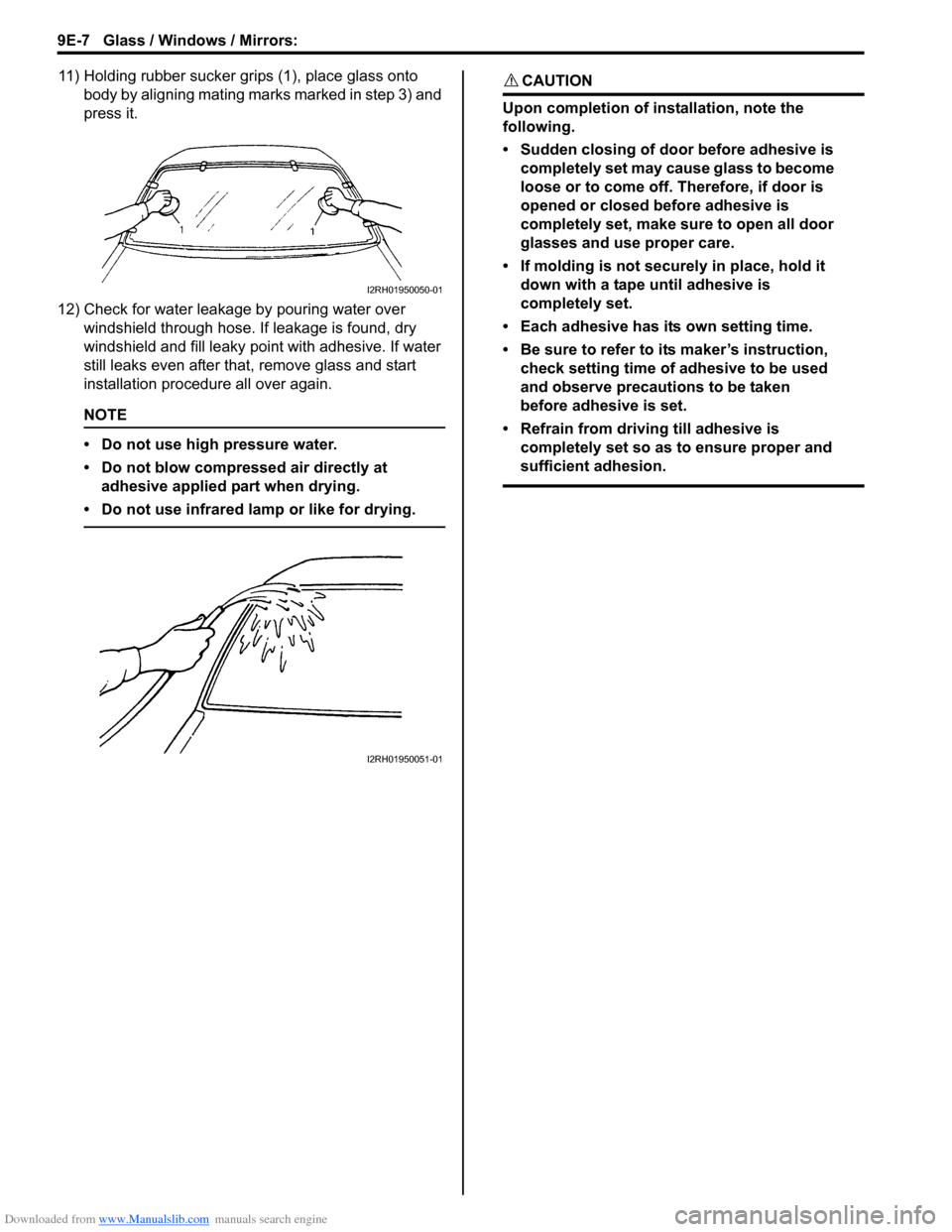
11) Holding rubber sucker grips (1), place glass onto body by aligning mating marks marked in step 3) and
press it.
12) Check for water leakage by pouring water over windshield through hose. If leakage is found, dry
windshield and fill leaky po int with adhesive. If water
still leaks even after that , remove glass and start
installation procedure all over again.
NOTE
• Do not use high pressure water.
• Do not blow compressed air directly at adhesive applied part when drying.
• Do not use infrared lamp or like for drying.
CAUTION!
Upon completion of installation, note the
following.
• Sudden closing of door before adhesive is completely set may cause glass to become
loose or to come off. Therefore, if door is
opened or closed before adhesive is
completely set, make sure to open all door
glasses and use proper care.
• If molding is not securely in place, hold it down with a tape until adhesive is
completely set.
• Each adhesive has its own setting time.
• Be sure to refer to its maker’s instruction, check setting time of adhesive to be used
and observe precautions to be taken
before adhesive is set.
• Refrain from driving till adhesive is completely set so as to ensure proper and
sufficient adhesion.
I2RH01950050-01
I2RH01950051-01
Page 1354 of 1496
Downloaded from www.Manualslib.com manuals search engine 9F-8 Security and Locks:
Front Door Lock Assembly InspectionS7RS0B9606003
• Check that door open and closes smoothly and properly.
• Check that door stops in the secondary latched position properly (preventing door from opening
freely) and that door closed completely in the fully
latched position.
• Adjust door latch striker position, if necessary.
Power Door Lock Switch InspectionS7RS0B9606004
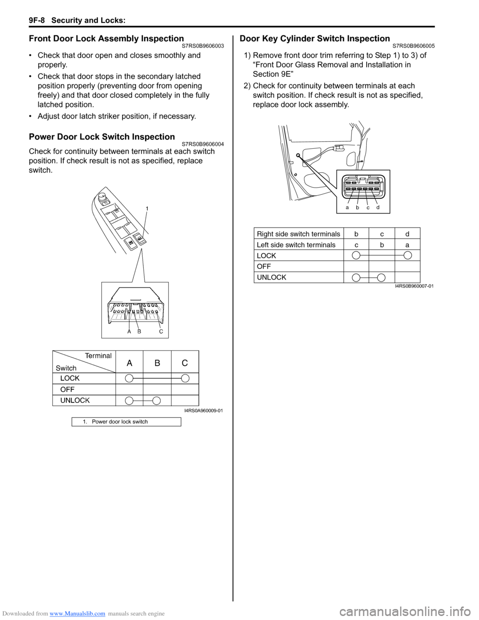
Check for continuity between terminals at each switch
position. If check result is not as specified, replace
switch.
Door Key Cylinder Switch InspectionS7RS0B9606005
1) Remove front door trim refe rring to Step 1) to 3) of
“Front Door Glass Remo val and Installation in
Section 9E”
2) Check for continuity between terminals at each switch position. If check resu lt is not as specified,
replace door lock assembly.
1. Power door lock switch
I4RS0A960009-01
a b c
LOCK
OFF
UNLOCK
bcd
cbaRight side switch terminals
Left side switch terminals
d
I4RS0B960007-01
Page 1356 of 1496
Downloaded from www.Manualslib.com manuals search engine 9F-10 Security and Locks:
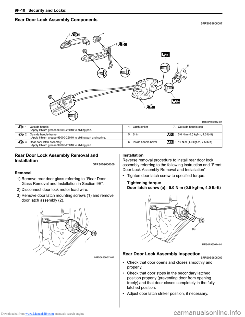
Rear Door Lock Assembly ComponentsS7RS0B9606007
Rear Door Lock Assembly Removal and
Installation
S7RS0B9606008
Removal1) Remove rear door glass referring to “Rear Door Glass Removal and Installation in Section 9E”.
2) Disconnect door lock motor lead wire.
3) Remove door latch mounting screws (1) and remove door latch assembly (2). Installation
Reverse removal procedure to install rear door lock
assembly referring to the following instruction and “Front
Door Lock Assembly Re
moval and Installation”.
• Tighten door latch screw to specified torque.
Tightening torque
Door latch screw (a): 5.0 N·m (0.5 kgf-m, 4.0 lb-ft)
Rear Door Lock Assembly InspectionS7RS0B9606009
• Check that door opens and closes smoothly and properly.
• Check that door stops in the secondary latched position properly (preventing door from opening
freely) and that door closes completely in the fully
latched position.
• Adjust door latch strike r position, if necessary.
(a)
(b)
1
7
2
6
3 4
5
I4RS0A960012-02
1. Outside handle
: Apply lithium grease 99000-25010 to sliding part. 4. Latch striker 7. Out side handle cap
2. Outside handle frame : Apply lithium grease 99000-25010 to sliding part and spring. 5. Shim : 5.0 N
⋅m (0.5 kgf-m, 4.0 lb-ft)
3. Rear door latch assembly : Apply lithium grease 99000-25010 to sliding part. 6. Inside handle bezel : 10 N
⋅m (1.0 kgf-m, 7.5 lb-ft)
1
2
I4RS0A960013-01
(a)
I4RS0A960014-01
Page 1358 of 1496
Downloaded from www.Manualslib.com manuals search engine 9F-12 Security and Locks:
Installation
Reverse removal procedure to install rear end door lock
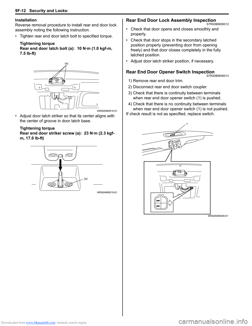
assembly noting the following instruction.
• Tighten rear end door latch bolt to specified torque.
Tightening torque
Rear end door latch bolt (a): 10 N·m (1.0 kgf-m,
7.5 lb-ft)
• Adjust door latch striker so that its center aligns with the center of groove in door latch base.
Tightening torque
Rear end door striker screw (a): 23 N·m (2.3 kgf-
m, 17.0 lb-ft)Rear End Door Lock Assembly InspectionS7RS0B9606012
• Check that door opens and closes smoothly and properly.
• Check that door stops in the secondary latched position properly (preventing door from opening
freely) and that door closes completely in the fully
latched position.
• Adjust door latch strike r position, if necessary.
Rear End Door Opener Switch InspectionS7RS0B9606013
1) Remove rear end door trim.
2) Disconnect rear end door switch coupler.
3) Check that there is continuity between terminals
when rear end door opener switch (1) is pushed.
4) Check that there is no continuity between terminals when rear end door opener switch (1) is not pushed.
If check result is not as specified, replace switch.
(a)
I4RS0A960018-01
(a)
I4RS0A960019-01
1
I4RS0A960020-01
Page 1364 of 1496
Downloaded from www.Manualslib.com manuals search engine 9G-2 Seats:
Front Seat Removal and InstallationS7RS0B9706002
WARNING!
Refer to “Air Bag Warning in Section 00” before starting service work.
Removal1) Disable air bag system referring to “Disabling Air Bag System in Section 8B”.
2) Disconnect couplers for seat harness and side air bag, if equipped.
3) Remove 4 mounting bolts to remove seat assembly.
4) Disassemble and repair seat if necessary.
Installation
Reverse removal procedure to install front seat.
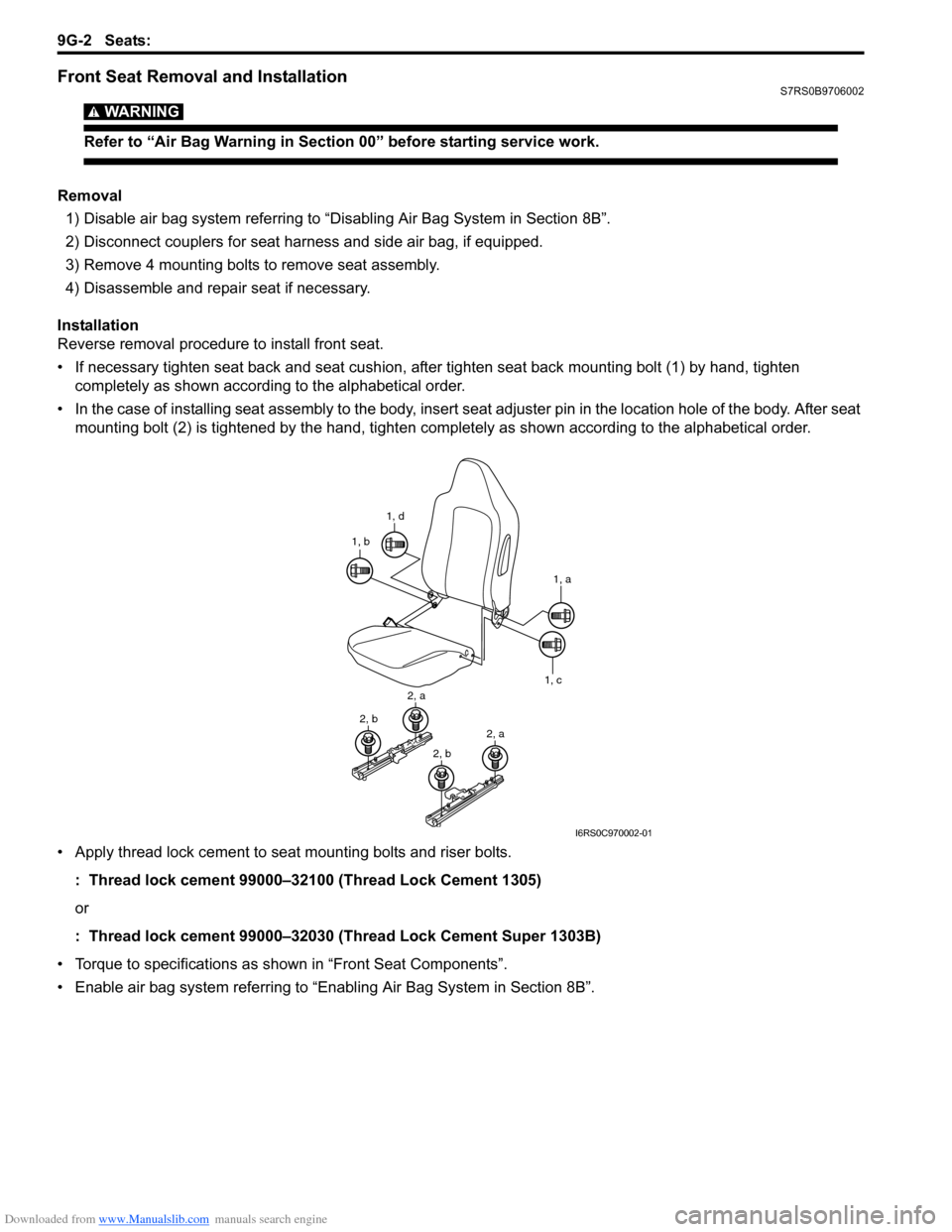
• If necessary tighten seat back and seat cushion, after tighten seat back mounting bolt (1) by hand, tighten completely as shown according to the alphabetical order.
• In the case of installing seat assembly to the body, insert se at adjuster pin in the location hole of the body. After seat
mounting bolt (2) is tightened by t he hand, tighten completely as shown according to the alphabetical order.
• Apply thread lock cement to seat mounting bolts and riser bolts. : Thread lock cement 99000–32100 (Thread Lock Cement 1305)
or
: Thread lock cement 99000–32030 (Thread Lock Cement Super 1303B)
• Torque to specifications as shown in “Front Seat Components”.
• Enable air bag system referring to “Enabling Air Bag System in Section 8B”.
1, d
1, b
1, a
1, c
2, a
2, b2, a
2, b
I6RS0C970002-01
Page 1370 of 1496
Downloaded from www.Manualslib.com manuals search engine 9J-1 Hood / Fenders / Doors:
Body, Cab and Accessories
Hood / Fenders / Doors
Repair Instructions
Hood Removal and InstallationS7RS0B9A06001
Removal
CAUTION!
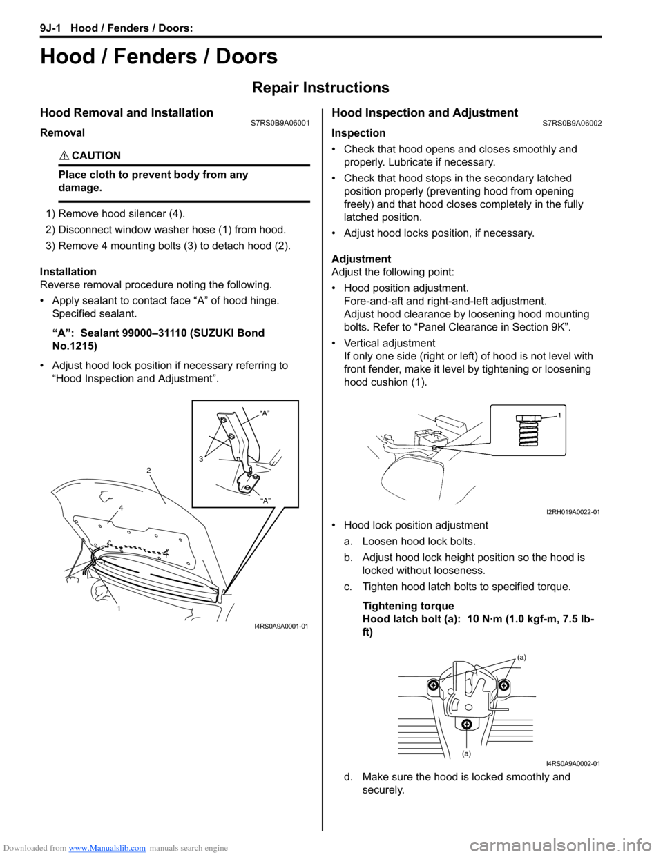
Place cloth to prevent body from any
damage.
1) Remove hood silencer (4).
2) Disconnect window washer hose (1) from hood.
3) Remove 4 mounting bolts (3) to detach hood (2).
Installation
Reverse removal procedure noting the following.
• Apply sealant to contact face “A” of hood hinge. Specified sealant.
“A”: Sealant 99000–31110 (SUZUKI Bond
No.1215)
• Adjust hood lock position if necessary referring to “Hood Inspection and Adjustment”.
Hood Inspection and AdjustmentS7RS0B9A06002
Inspection
• Check that hood opens and closes smoothly and properly. Lubricate if necessary.
• Check that hood stops in the secondary latched position properly (preventing hood from opening
freely) and that hood closes completely in the fully
latched position.
• Adjust hood locks position, if necessary.
Adjustment
Adjust the following point:
• Hood position adjustment. Fore-and-aft and right-and-left adjustment.
Adjust hood clearance by loosening hood mounting
bolts. Refer to “Panel Clearance in Section 9K”.
• Vertical adjustment If only one side (right or left) of hood is not level with
front fender, make it level by tightening or loosening
hood cushion (1).
• Hood lock position adjustment a. Loosen hood lock bolts.
b. Adjust hood lock height position so the hood is locked without looseness.
c. Tighten hood latch bolts to specified torque.
Tightening torque
Hood latch bolt (a): 10 N·m (1.0 kgf-m, 7.5 lb-
ft)
d. Make sure the hood is locked smoothly and securely.
“A”
“A”
3
2
4
1
I4RS0A9A0001-01
I2RH019A0022-01
(a)
(a)I4RS0A9A0002-01