2006 SUZUKI SWIFT instrumen
[x] Cancel search: instrumenPage 2 of 1496
Downloaded from www.Manualslib.com manuals search engine IMPORTANT
WARNING/CAUTION/NOTE
Please read this manual and follow its instructions carefully. To emphasize special information, the words , and NOTE have special meanings. Pay specia l attention to the messages high-
lighted by these signal words.
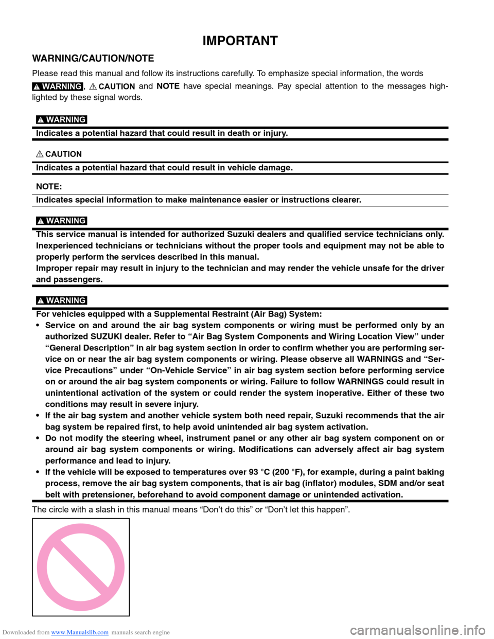
The circle with a slash in this manual me ans “Don’t do this” or “Don’t let this happen”.
WARNING!CAUTION!
Indicates a potential hazard that could result in death or injury.
WARNING!
Indicates a potential hazard that could result in vehicle damage.
CAUTION!
NOTE:
Indicates special information to make main tenance easier or instructions clearer.
This service manual is intended for authorized Su zuki dealers and qualified service technicians only.
Inexperienced technicians or technicians without the proper tools and equipment may not be able to
properly perform the services described in this manual.
Improper repair may result in injury to the technician and may render the vehicle unsafe for the driver
and passengers.
WARNING!
For vehicles equipped with a Supplemental Restraint (Air Bag) System:
• Service on and around the air bag system components or wiring must be performed only by an authorized SUZUKI dealer. Refer to “Air Bag System Components and Wiring Location View” under
“General Description” in air bag system section in order to confirm whether you are performing ser-
vice on or near the air bag system components or wiring. Please observe all WARNINGS and “Ser-
vice Precautions” under “On-Vehicl e Service” in air bag system section before performing service
on or around the air bag system components or wiring. Failure to follow WARNINGS could result in
unintentional activation of the system or could re nder the system inoperative. Either of these two
conditions may result in severe injury.
If the air bag system and another vehicle system both need repair, Suzuki recommends that the air
bag system be repaired first, to help av oid unintended air bag system activation.
Do not modify the steering wheel, instrument pa nel or any other air bag system component on or
around air bag system components or wiring. Modi fications can adversely affect air bag system
performance and lead to injury.
If the vehicle will be exposed to temperatures over 93 °C (200 °F), for example, during a paint baking
process, remove the air bag system components, th at is air bag (inflator) modules, SDM and/or seat
belt with pretensioner, beforehand to avoid component damage or unintended activation.
WARNING!
Page 4 of 1496

Downloaded from www.Manualslib.com manuals search engine 00
0
1
2
3
4
5
6
7
8
9
10
11
Vo l u m e 1
Precautions............................................................... 00-iPrecautions ............................................................ 00-1
General Information ................ ................................... 0-i
General Information ............................................... 0A-1
Maintenance and Lubricatio n ................................. 0B-1
Engine ......................................................................... 1-i Precautions .............................................................. 1-1
Engine General Information and Diagnosis ........... 1A-1
Aux. Emission Control Devices .............................. 1B-1
Engine Electrical Devices....................................... 1C-1
Engine Mechanical ................................................. 1D-1
Engine Lubrication System .................................... 1E-1
Engine Cooling System .......................................... 1F-1
Fuel System ...........................................................1G-1
Ignition System....................................................... 1H-1
Starting System ....................................................... 1I-1
Charging System.....................................................1J-1
Exhaust System ..................................................... 1K-1
Suspension ................................................................. 2-i Precautions .............................................................. 2-1
Suspension General Diagnosis .............................. 2A-1
Front Suspension ................................................... 2B-1
Rear Suspension................ .................................... 2C-1
Wheels and Tires ................................................... 2D-1
Driveline / Axle ........................................................... 3-i Precautions .............................................................. 3-1
Drive Shaft / Axle ................................................... 3A-1
Brakes ......................................................................... 4-i Precautions .............................................................. 4-1
Brake Control System and Diagnosis .................... 4A-1
Front Brakes........................................................... 4B-1
Rear Brakes ........................................................... 4C-1
Parking Brake......................................................... 4D-1
ABS ........................................................................ 4E-1
Electronic Stability Program ................................... 4F-1
Vo l u m e 2
Precautions ............................................................... 00-iPrecautions ............................................................ 00-1
Transmission / Transaxle .... ...................................... 5-i
Precautions .............................................................. 5-1
Automatic Transmission/Transaxle ........................ 5A-1
Manual Transmission/Transaxle ............................ 5B-1
Clutch .....................................................................5C-1
Steering ....................................................................... 6-i Precautions .............................................................. 6-1
Steering General Diagnosis ................................... 6A-1
Steering Wheel and Column .................................. 6B-1
Power Assisted Steering System ...........................6C-1
HVAC ........................................................................... 7-i Precautions .............................................................. 7-1
Heater and Ventilation............................................ 7A-1
Air Conditioning System ......................................... 7B-1
Restraint ...................................................................... 8-i Precautions .............................................................. 8-1
Seat Belts ............................................................... 8A-1
Air Bag System ...................................................... 8B-1
Body, Cab and Accessories .... .................................. 9-i
Precautions .............................................................. 9-1
Wiring Systems ...................................................... 9A-1
Lighting Systems .................................................... 9B-1
Instrumentation / Driver Info. / Horn .......................9C-1
Wipers / Washers ...................................................9D-1
Glass / Windows / Mirrors ...................................... 9E-1
Security and Locks ................................................. 9F-1
Seats ..................................................................... 9G-1
Interior Trim ............................................................9H-1
Hood / Fenders / Doors .......................................... 9J-1
Body Structure ....................................................... 9K-1
Paint / Coatings ...................................................... 9L-1
Exterior Trim .......................................................... 9M-1
Control Systems ....................................................... 10-i Precautions ............................................................ 10-1
Body Electrical Control Sy stem ............................ 10B-1
Immobilizer Control System .................................10C-1
Keyless Start System ........................................... 10E-1
TABLE OF CONTENTS
Page 6 of 1496
Downloaded from www.Manualslib.com manuals search engine 00-1 Precautions:
Precautions
Precautions
Precautions
Precautions for Vehicles Equipped with a
Supplemental Restraint (Air Bag) System
S7RS0B0000001
WARNING!
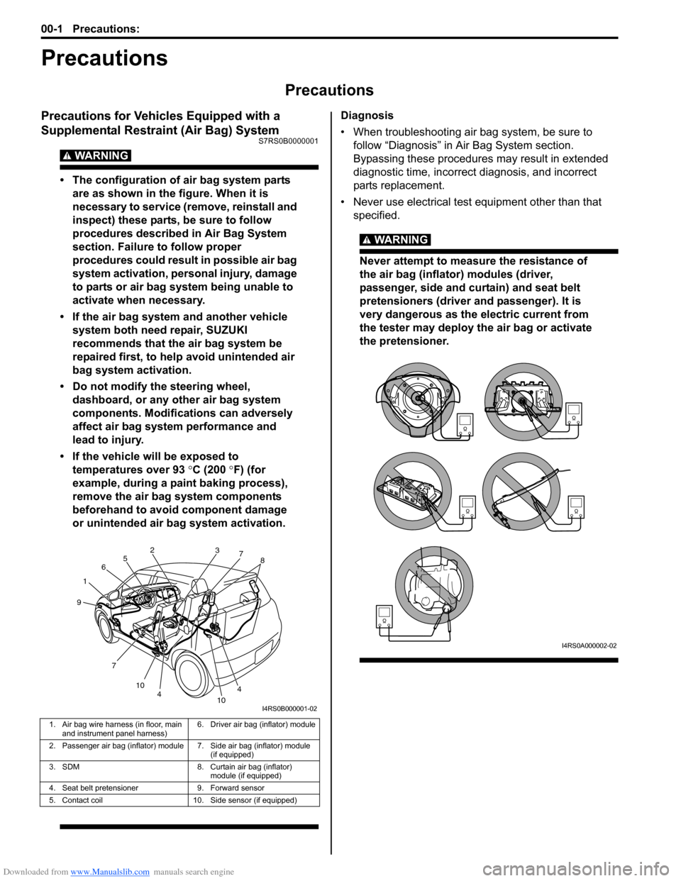
• The configuration of air bag system parts are as shown in the figure. When it is
necessary to service (remove, reinstall and
inspect) these parts, be sure to follow
procedures described in Air Bag System
section. Failure to follow proper
procedures could result in possible air bag
system activation, personal injury, damage
to parts or air bag system being unable to
activate when necessary.
• If the air bag system and another vehicle system both need repair, SUZUKI
recommends that the air bag system be
repaired first, to help avoid unintended air
bag system activation.
• Do not modify the steering wheel, dashboard, or any other air bag system
components. Modifications can adversely
affect air bag system performance and
lead to injury.
• If the vehicle will be exposed to temperatures over 93 °C (200 °F) (for
example, during a paint baking process),
remove the air bag system components
beforehand to avoid component damage
or unintended air bag system activation.
Diagnosis
• When troubleshooting air bag system, be sure to follow “Diagnosis” in Air Bag System section.
Bypassing these procedures may result in extended
diagnostic time, incorrect diagnosis, and incorrect
parts replacement.
• Never use electrical test equipment other than that specified.
WARNING!
Never attempt to measure the resistance of
the air bag (inflator) modules (driver,
passenger, side and curtain) and seat belt
pretensioners (driver and passenger). It is
very dangerous as the electric current from
the tester may deploy the air bag or activate
the pretensioner.
1. Air bag wire harness (in floor, main and instrument panel harness) 6. Driver air bag (inflator) module
2. Passenger air bag (inflator) module 7. Side air bag (inflator) module (if equipped)
3. SDM 8. Curtain air bag (inflator) module (if equipped)
4. Seat belt pretensioner 9. Forward sensor
5. Contact coil 10. Side sensor (if equipped)
1 2
3
4
4
5
6
7 7
8
9
10 10
I4RS0B000001-02
I4RS0A000002-02
Page 8 of 1496
Downloaded from www.Manualslib.com manuals search engine 00-3 Precautions:
WARNING!
SDM
• For handling and storage of a SDM, select a place where the ambient temperature
below 65 °C (150 °F), without high humidity
and away from electric noise.
• During service procedures, be very careful when handling a Sensing and Diagnostic
Module (SDM). Never strike or jar the SDM.
• Never power up the air bag system when the SDM is not rigidly attached to the
vehicle. All SDM and mounting bracket
fasteners must be carefully torqued and
the arrow must be pointing toward the
front of the vehicle to ensure proper
operation of the air bag system.
The SDM could be activated when powered
while not rigidly att ached to the vehicle
which could cause deployment and result
in personal injury.
WARNING!
Driver and Passenger Seat Belt
Pretensioners
• For handling and storage of a live seat belt pretensioner, select a place where the
ambient temperature below 65 °C (150 ° F),
without high humidity and away from
electric noise.
• Never carry seat belt pretensioner by wire or connector of pretensioner. When
placing a live seat belt pretensioner on the
workbench or some place like that, never
put something on seat belt pretensioner.
Otherwise, personal injury may result.
• Never dispose of live (inactivated) seat belt pretensioners (drive and passenger). If
disposal is necessary, be sure to activate
them according to activation procedures
described in “Air Bag (Inflator) Module and
Seat Belt Pretensioner Disposal in Section
8B” before disposal.
• The seat belt pretensioner immediately after activation is very hot. Wait for at least
half an hour to cool it off before
proceeding the work.
• With many service procedures, gloves and safety glasses should be worn to prevent
any possible irritation of the skin or eyes.
• Even when the accident was light enough not to cause air bags to activate, be sure to inspect system
parts and other related parts according to instructions
under “Repair and Inspection Required after Accident
in Section 8B”.
• When servicing parts other than air bag system, if shocks may be applied to air bag system component
parts, remove those parts beforehand.
• When handling the air bag (inflator) modules (driver, passenger, side and curtain), seat belt pretensioners
(driver and passenger), forward sensor, side sensors
or SDM, be careful not to drop it or apply an impact to
it. If an excessive impact was applied, never attempt
disassembly or repair but replace it with a new one.
• When grease, cleaning agent, oil, water, etc. has got onto air bag (inflator) modules (driver, passenger, side
and curtain) or seat belt pretensioners (drive and
passenger), wipe off immediately with a dry cloth.
• Air bag wire harness is included in floor and instrument panel wire harnesses. Air bag wire
harness branched off from floor and instrument panel
wire harnesses can be identifie d easily as it is covered
with a yellow protection tube and it has yellow
connectors. Be very ca reful when handling it.
• When an open in air bag wire harness, damaged wire harness, connector or terminal is found, replace wire
harness, connectors and terminals as an assembly.
• Do not apply power to the air bag system unless all components are connected or a diagnostic flow
requests it, as this will set a DTC.
• Never use air bag system component parts from another vehicle.
• When using electric welding, be sure to disconnect all air bag (inflator) module connectors and pretensioner
connectors from air bag wire harness respectively.
• Never expose air bag system component parts directly to hot air (drying or baking the vehicle after
painting) or flames.
• WARNING / CAUTION labels are attached on each
part of air bag system components. Be sure to follow
the instructions.
• After vehicle is completely repaired, perform “Air Bag Diagnostic System Check in Section 8B”.
Page 28 of 1496
Downloaded from www.Manualslib.com manuals search engine 0A-7 General Information:
Engine Supporting PointsS7RS0B0101006
WARNING!
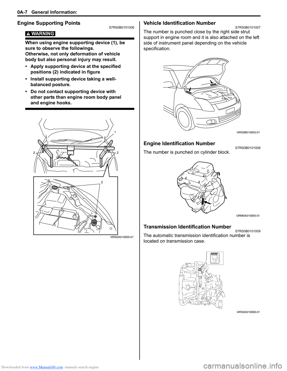
When using engine supporting device (1), be
sure to observe the followings.
Otherwise, not only deformation of vehicle
body but also personal injury may result.
• Apply supporting device at the specified positions (2) indicated in figure
• Install supporting device taking a well- balanced posture.
• Do not contact supporting device with other parts than engine room body panel
and engine hooks.
Vehicle Identification NumberS7RS0B0101007
The number is punched close by the right side strut
support in engine room and it is also attached on the left
side of instrument panel depending on the vehicle
specification.
Engine Identification NumberS7RS0B0101008
The number is punched on cylinder block.
Transmission Identification NumberS7RS0B0101009
The automatic transmission identification number is
located on transmission case.
2
2
2
1
I4RS0A010005-01
I4RS0B010003-01
I3RM0A010005-01
I4RS0A010008-01
Page 76 of 1496
Downloaded from www.Manualslib.com manuals search engine 1A-26 Engine General Information and Diagnosis:
DTC CheckS7RS0B1104003
NOTE
• There are two types of OBD system depending on the vehicle specification.
For details, refer to “Precaution on On-
Board Diagnostic (OBD) System”.
• The MIL is turned on when the ECM and/or TCM detect malfunction(s). Each ECM and
TCM stores diagnostic information as the
diagnostic trouble code (DTC) in its
memory and outputs th e DTC to the scan
tool.
Therefore, check both of the ECM and TCM
for any DTC with the SUZUKI scan tool
because the DTC stored in ECM and TCM
is not read and displayed at a time.
However, each of the ECM and TCM needs
not to be checked with the generic scan
tool because the DTC stored in ECM and
TCM is read and displayed at a time.
Using Scan Tool
1) Prepare OBD generic scan tool or SUZUKI scan tool.
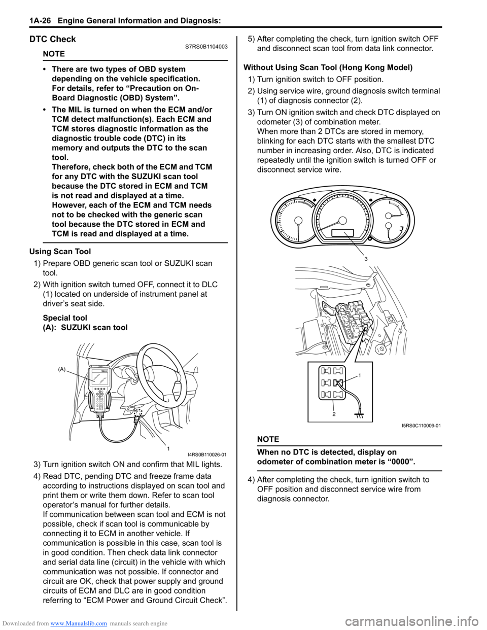
2) With ignition switch turned OFF, connect it to DLC (1) located on underside of instrument panel at
driver’s seat side.
Special tool
(A): SUZUKI scan tool
3) Turn ignition switch ON and confirm that MIL lights.
4) Read DTC, pending DTC and freeze frame data according to instructions displayed on scan tool and
print them or write them down. Refer to scan tool
operator’s manual for further details.
If communication between scan tool and ECM is not
possible, check if scan tool is communicable by
connecting it to ECM in another vehicle. If
communication is possible in this case, scan tool is
in good condition. Then check data link connector
and serial data line (circuit) in the vehicle with which
communication was not possible. If connector and
circuit are OK, check that power supply and ground
circuits of ECM and DLC are in good condition
referring to “ECM Power and Ground Circuit Check”. 5) After completing the check,
turn ignition switch OFF
and disconnect scan tool from data link connector.
Without Using Scan Tool (Hong Kong Model) 1) Turn ignition switch to OFF position.
2) Using service wire, ground diagnosis switch terminal (1) of diagnosis connector (2).
3) Turn ON ignition switch and check DTC displayed on
odometer (3) of combination meter.
When more than 2 DTCs are stored in memory,
blinking for each DTC star ts with the smallest DTC
number in increasing order. Also, DTC is indicated
repeatedly until the ignition switch is turned OFF or
disconnect service wire.
NOTE
When no DTC is detected, display on
odometer of combinatio n meter is “0000”.
4) After completing the check, turn ignition switch to
OFF position and disconnect service wire from
diagnosis connector.
(A)
1
I4RS0B110026-01
21
3
I5RS0C110009-01
Page 580 of 1496
Downloaded from www.Manualslib.com manuals search engine 4F-6 Electronic Stability Program:
Warning Lamp, Indicator Lamp DescriptionS7RS0B4601003
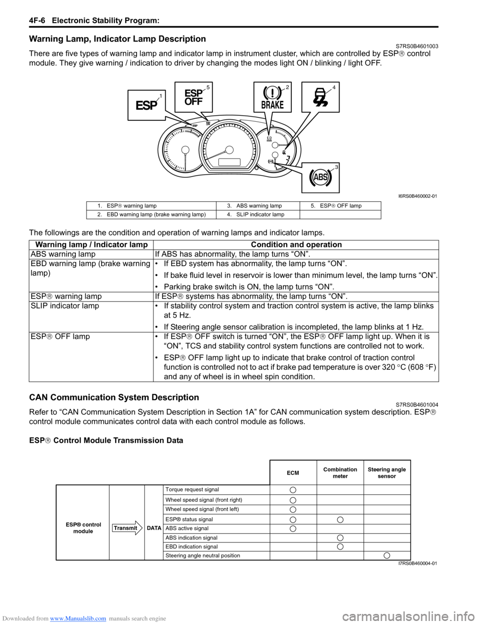
There are five types of warning lamp and indicator lamp in instrument cluster, which are controlled by ESP ® control
module. They give warning / indication to driver by changing the modes light ON / blinking / light OFF.
The followings are the condition and operation of warning lamps and indicator lamps.
CAN Communication System DescriptionS7RS0B4601004
Refer to “CAN Communication System Description in Section 1A” for CAN communication system description. ESP ®
control module communicates control data with each control module as follows.
ESP ® Control Module Transmission Data
1
245
3
I6RS0B460002-01
1. ESP ® warning lamp 3. ABS warning lamp 5. ESP ® OFF lamp
2. EBD warning lamp (brake warning lamp) 4. SLIP indicator lamp
Warning lamp / Indicator lamp Condition and operation
ABS warning lamp If ABS has abnor mality, the lamp turns “ON”.
EBD warning lamp (brake warning
lamp) • If EBD system has abnormality, the lamp turns “ON”.
• If bake fluid level in reservoir is lower
than minimum level, the lamp turns “ON”.
• Parking brake switch is ON, the lamp turns “ON”.
ESP ® warning lamp If ESP ® systems has abnormality, the lamp turns “ON”.
SLIP indicator lamp • If stability cont rol system and traction control system is active, the lamp blinks
at 5 Hz.
• If Steering angle sensor calibration is incompleted, the lamp blinks at 1 Hz.
ESP ® OFF lamp • If ESP ® OFF switch is turned “ON”, the ESP ® OFF lamp light up. When it is
“ON”, TCS and stability control system functions are controlled not to work.
• ESP® OFF lamp light up to indicate th at brake control of traction control
function is controlled not to act if brake pad temperature is over 320 °C (608 °F)
and any of wheel is in wheel spin condition.
Combination
meter
Transmit DATA
ESP® control
moduleECMSteering angle sensor
Torque request signal
Wheel speed signal (front right)
Wheel speed signal (front left)
ESP® status signal
ABS active signal
ABS indication signal
EBD indication signal
Steering angle neutral position
I7RS0B460004-01
Page 878 of 1496
Downloaded from www.Manualslib.com manuals search engine 6B-7 Steering Wheel and Column:
Steering Column Removal and InstallationS7RS0B6206006
CAUTION!
Once the steering column is removed from
the vehicle, the column is extremely
susceptible to damage.
• Dropping the column assembly on its end could collapse the steering shaft or loosen
the plastic shear pins which maintain
column length.
• Leaning on the column assembly could cause it to bend or deform.
Any of the damage could impair the column’s
collapsible design.
Steering column mounting nuts should not
be loosened with steering shaft joint upper
side bolt tightened as this could cause
damage to shaft joint bearing.
NOTE
When servicing steering column or any
column-mounted component, remove
steering wheel. But when removing steering
column simply to gain access to instrument
panel components, leave steering wheel
installed on steering column.
Removal
WARNING!
Never rest a steering column assembly on
the steering wheel with the air bag (inflator)
module face down and column vertical.
Otherwise, personal injury may result.
1) Disconnect negative (–) cable at battery.
2) Disable air bag system. Re fer to “Disabling Air Bag
System in Section 8B”.
3) Remove steering wheel and contact coil cable assembly referring to “S teering Wheel Removal and
Installation” and “Contact Coil Cable Assembly
Removal and Installation”.
4) Detach lighting switch and wiper switch from steering column.
5) Remove immobilizer cont rol module from steering
column, referring to “Immo bilizer Control Module
(ICM) Removal and Installation in Section 10C”.
6) Remove steering column hole cover.
7) Remove steering joint cover.
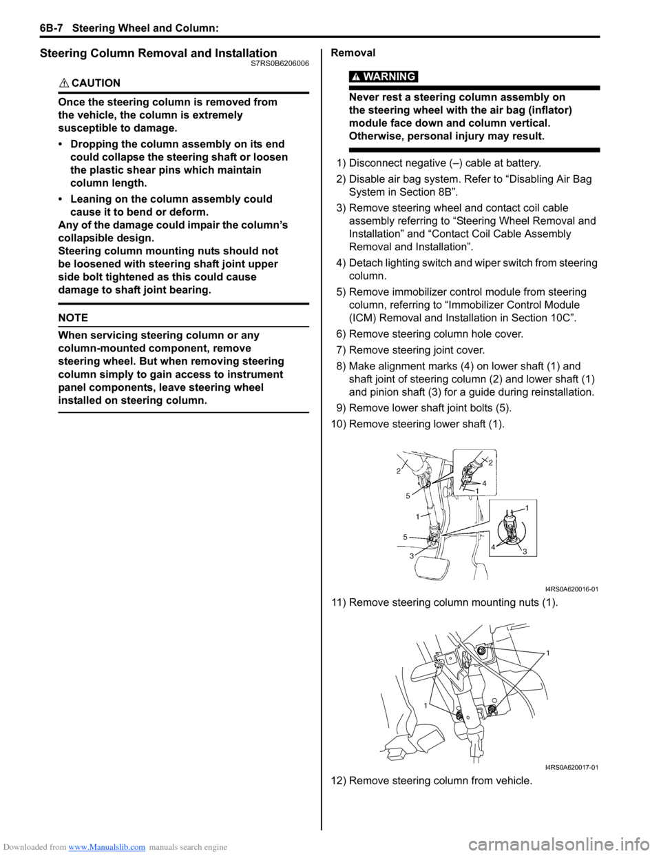
8) Make alignment marks (4) on lower shaft (1) and shaft joint of steering column (2) and lower shaft (1)
and pinion shaft (3) for a guide during reinstallation.
9) Remove lower shaf t joint bolts (5).
10) Remove steering lower shaft (1).
11) Remove steering column mounting nuts (1).
12) Remove steering column from vehicle.
I4RS0A620016-01
1
1
I4RS0A620017-01