Page 467 of 1496
Downloaded from www.Manualslib.com manuals search engine Rear Suspension: 2C-13
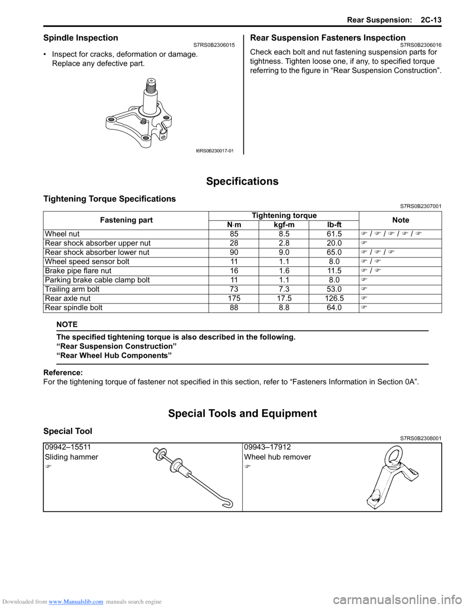
Spindle InspectionS7RS0B2306015
• Inspect for cracks, deformation or damage.Replace any defective part.
Rear Suspension Fasteners InspectionS7RS0B2306016
Check each bolt and nut fastening suspension parts for
tightness. Tighten loose one, if any, to specified torque
referring to the figure in “Rear Suspension Construction”.
Specifications
Tightening Torque SpecificationsS7RS0B2307001
NOTE
The specified tightening torque is also described in the following.
“Rear Suspension Construction”
“Rear Wheel Hub Components”
Reference:
For the tightening torque of fastener not specified in this section, refer to “Fasteners Information in Section 0A”.
Special Tools and Equipment
Special ToolS7RS0B2308001
I6RS0B230017-01
Fastening part Tightening torque
Note
N ⋅mkgf-mlb-ft
Wheel nut 85 8.5 61.5 �) / �) / �) / �) / �)
Rear shock absorber upper nut 28 2.8 20.0 �)
Rear shock absorber lower nut 90 9.0 65.0 �) / �) / �)
Wheel speed sensor bolt 11 1.1 8.0 �) / �)
Brake pipe flare nut 16 1.6 11.5 �) / �)
Parking brake cable clamp bolt 11 1.1 8.0 �)
Trailing arm bolt 73 7.3 53.0 �)
Rear axle nut 175 17.5 126.5 �)
Rear spindle bolt 88 8.8 64.0 �)
09942–1551109943–17912
Sliding hammer Wheel hub remover
�)�)
Page 536 of 1496
Downloaded from www.Manualslib.com manuals search engine 4D-1 Parking Brake:
Brakes
Parking Brake
General Description
Parking Brake Cable ConstructionS7RS0B4401001
I6RS0B440001-01
T: Top side3. Equalizer8. Lever [C]: View [C]
F: Front side 4. Parking cable bracket9. Parking cable clamp bolt [D]: View [D]
R: Right side 5. Parking cable bracket bolt 10. Vehicle body : 25 N⋅m (2.5 kgf-m, 18.0 lb-ft)
1. Parking brake lever assembly 6. Grommet [A]: View [A]: 11 N⋅m (1.1 kgf-m, 8.0 lb-ft)
2. Parking brake lever bolt 7. E-ring[B]: View [B]
Page 538 of 1496
Downloaded from www.Manualslib.com manuals search engine 4D-3 Parking Brake:
6) Release parking brake lever and then make sure that there is no drag in rear wheel.
If there is, repeats go to step 2).
7) Make sure that the number of notch is between 4 and 9 when operating parking brake lever.
8) If the number of notch is not between 4 and 9, replace parking brake cable and/or inspect rear
brake caliper.
Parking brake stroke
When lever is pulled up at 200 N (20kg, 44lbs) : 4
to 9 notches
Parking Brake Cable Removal and InstallationS7RS0B4406002
Removal
NOTE
When it is necessary to remove both right
and left parking brake cables, repeat below
steps 2) and 5) on right and left wheels.
1) Hoist vehicle.
2) Remove wheel.
3) Disconnect parking brake cable from equalizer (parking brake lever) and clamps.
4) Disconnect parking brake cable from lever referring to “Rear Disc Brake Caliper Removal and Installation
in Section 4C”.
5) Remove parking brake cable and parking cable bracket.
Installation
Install it by reversing removal procedure, noting the
following points.
• Install clamps properly referring to “Parking Brake Cable Construction”.
• Tighten bolts and nuts to specified torque referring to “Parking Brake Cable Construction”.
Tightening torque
Parking brake lever bolt: 25 N·m (2.5 kgf-m, 18.0
lb-ft)
Parking cable clamp bolt: 11 N·m (1.1 kgf-m, 8.0
lb-ft)
Parking cable bracket bolt: 25 N·m (2.5 kgf-m,
18.0 lb-ft)
• Adjust parking brake cable. Refer to “Parking Brake Inspection and Adjustment”.
• Check brake disc for dragging and brake system for proper performance. Brake test should be performed.
Parking Brake Lever Removal and InstallationS7RS0B4406003
Removal
1) Remove console box.
2) Block vehicle wheels and release parking brake lever.
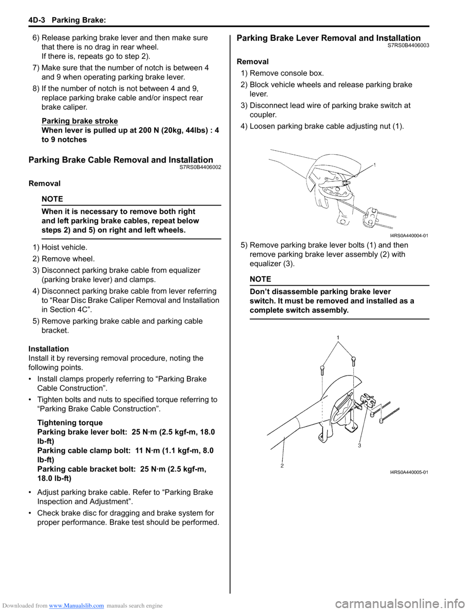
3) Disconnect lead wire of parking brake switch at coupler.
4) Loosen parking brake cable adjusting nut (1).
5) Remove parking brake lever bolts (1) and then remove parking brake lever assembly (2) with
equalizer (3).
NOTE
Don’t disassemble parking brake lever
switch. It must be removed and installed as a
complete switch assembly.
I4RS0A440004-01
I4RS0A440005-01
Page 539 of 1496
Downloaded from www.Manualslib.com manuals search engine Parking Brake: 4D-4
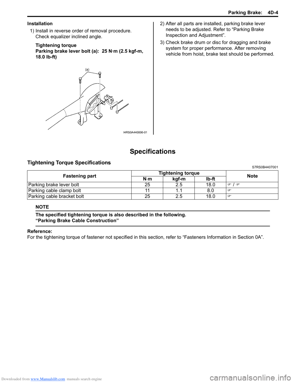
Installation1) Install in reverse order of removal procedure. Check equalizer inclined angle.
Tightening torque
Parking brake lever bolt (a): 25 N·m (2.5 kgf-m,
18.0 lb-ft) 2) After all parts are installed, parking brake lever
needs to be adjusted. Refer to “Parking Brake
Inspection and Adjustment”.
3) Check brake drum or disc for dragging and brake system for proper performance. After removing
vehicle from hoist, brake test should be performed.
Specifications
Tightening Torque SpecificationsS7RS0B4407001
NOTE
The specified tightening torque is also described in the following.
“Parking Brake Cable Construction”
Reference:
For the tightening torque of fastener not specified in this section, refer to “Fasteners Information in Section 0A”.
I4RS0A440006-01
Fastening part Tightening torque
Note
N ⋅mkgf-mlb-ft
Parking brake lever bolt 25 2.5 18.0 �) / �)
Parking cable clamp bolt 11 1.1 8.0 �)
Parking cable bracket bolt 25 2.5 18.0 �)
Page 546 of 1496
Downloaded from www.Manualslib.com manuals search engine 4E-7 ABS:
Component Location
ABS Components LocationS7RS0B4503001
Front Wheel Speed Sensor Components LocationS7RS0B4503002
14
5
3
2 2
2
2
6
6
6
6
7
8
I6RS0C450005-01
1. ABS hydraulic unit / control module assembly
5. EBD warning light (Brake warning light)
2. Wheel speed sensors 6. Wheel speed sensor rings
3. Stop lamp switch 7. Data link connector
4. ABS warning light 8. ECM
[A]
[B]
1 1
2
3
4
1
(a)
(b)
5I6RS0C450016-01
[A]: OK 2. Grommet5. Front wheel bearing
[B]: NG 3. Connector: 25 N⋅m (2.5 kgf-m, 18.0 lb-ft)
1. Front wheel speed sensor 4. Sensor ring: 11 N⋅m (1.1 kgf-m, 8.0 lb-ft)
Page 547 of 1496

Downloaded from www.Manualslib.com manuals search engine ABS: 4E-8
Rear Wheel Speed Sensor Components LocationS7RS0B4503003
Diagnostic Information and Procedures
ABS CheckS7RS0B4504001
Refer to the following items for the details of each step.
12
3
4
[A]
[B]1
1
(a)
(a)
I6RS0C450006-01
[A]: OK
1. Rear wheel speed sensor 3. Connector: 11 N⋅m (1.1 kgf-m, 8.0 lb-ft)
[B]: NG 2. Sensor ring 4. Grommet
StepAction YesNo
1 �) Malfunction analysis
1) Perform “Customer complaint analysis: ”.
2) Perform “Problem symptom confirmation: ”.
3) Perform “DTC check, record and clearance: ” and recheck DTC.
Is there any malfunction DTC? Go to Step 4.
Go to Step 2.
2 �) Driving test
1) Perform “Step 2: Driving Test: ”.
Is trouble symptom identified? Go to Step 3.
Go to Step 6.
3 �) DTC check
1) Perform “DTC Check”.
Is it malfunction code? Go to Step 4.
Go to Step 5.
4 �) ABS check
1) Inspect and repair referring to applicable DTC flow.
Does trouble recur? Go to Step 5.
Go to Step 7.
5 �) Brakes diagnosis
1) Inspect and repair referring to “Brakes Symptom Diagnosis in Section 4A”.
Does trouble recur? Go to Step 3.
Go to Step 7.
Page 571 of 1496
Downloaded from www.Manualslib.com manuals search engine ABS: 4E-32
Front Wheel Speed Sensor Removal and
Installation
S7RS0B4506006
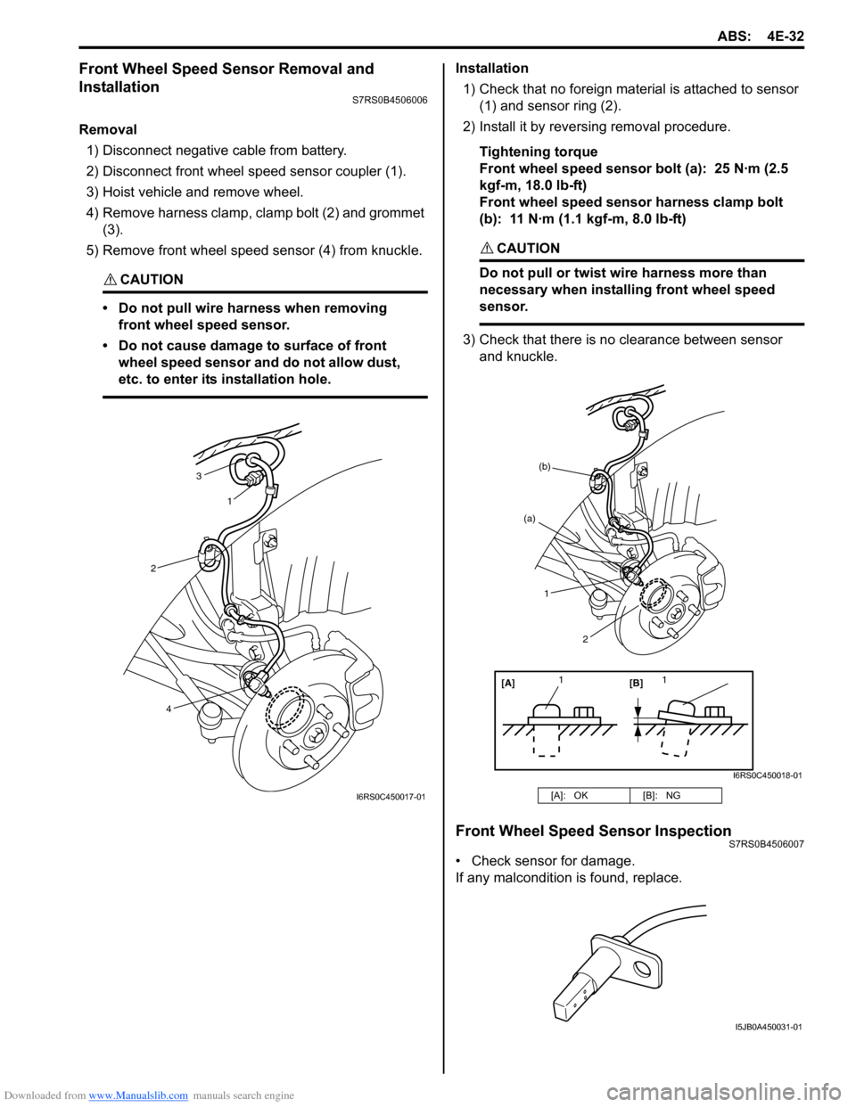
Removal1) Disconnect negative cable from battery.
2) Disconnect front wheel speed sensor coupler (1).
3) Hoist vehicle and remove wheel.
4) Remove harness clamp, clamp bolt (2) and grommet (3).
5) Remove front wheel speed sensor (4) from knuckle.
CAUTION!
• Do not pull wire ha rness when removing
front wheel speed sensor.
• Do not cause damage to surface of front wheel speed sensor and do not allow dust,
etc. to enter its installation hole.
Installation
1) Check that no foreign material is attached to sensor (1) and sensor ring (2).
2) Install it by reversing removal procedure.
Tightening torque
Front wheel speed sensor bolt (a): 25 N·m (2.5
kgf-m, 18.0 lb-ft)
Front wheel speed sensor harness clamp bolt
(b): 11 N·m (1.1 kgf-m, 8.0 lb-ft)
CAUTION!
Do not pull or twist wire harness more than
necessary when installing front wheel speed
sensor.
3) Check that there is no clearance between sensor
and knuckle.
Front Wheel Speed Sensor InspectionS7RS0B4506007
• Check sensor for damage.
If any malcondition is found, replace.
3
1
2
4
I6RS0C450017-01[A]: OK [B]: NG
[A][B]
11
(a)
(b)
1
2
I6RS0C450018-01
I5JB0A450031-01
Page 572 of 1496
Downloaded from www.Manualslib.com manuals search engine 4E-33 ABS:
Rear Wheel Speed Sensor Removal and
Installation
S7RS0B4506008
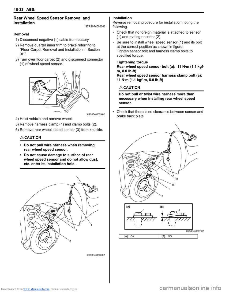
Removal1) Disconnect negative (–) cable from battery.
2) Remove quarter inner trim to brake referring to “Floor Carpet Removal a nd Installation in Section
9H”.
3) Turn over floor carpet (2) and disconnect connector (1) of wheel speed sensor.
4) Hoist vehicle and remove wheel.
5) Remove harness clamp (1) and clamp bolts (2).
6) Remove rear wheel speed sensor (3) from knuckle.
CAUTION!
• Do not pull wire harness when removing rear wheel speed sensor.
• Do not cause damage to surface of rear wheel speed sensor and do not allow dust,
etc. enter its installation hole.
Installation
Reverse removal procedure for installation noting the
following.
• Check that no foreign material is attached to sensor (1) and mating encoder (2).
• Be sure to install wheel speed sensor (1) and its bolt at the correct position as shown in figure.
Tighten sensor bolt and harness clamp bolts to
specified torque.
Tightening torque
Rear wheel speed sensor bolt (a): 11 N·m (1.1 kgf-
m, 8.0 lb-ft)
Rear wheel speed sensor harness clamp bolt (a):
11 N·m (1.1 kgf-m, 8.0 lb-ft)
CAUTION!
Do not pull or twist wire harness more than
necessary when installing rear wheel speed
sensor.
• Check that there is no clearance between sensor and brake back plate.
2
2
1
I6RS0B460035-02
3
2
1
I6RS0B460036-02
[A]: OK [B]: NG
1
(b)
[A][B]
11
(a)
2
I6RS0B460037-02